

Energies 2018, 11, 2463 |
10 of 20 |
emergencies or when the plug is accidentally removed from the socket while the power is still on. During those cases, the plug and socket should be capable of taking care of the arc extinction and shock prevention tasks.
4.3. Grounding Methods
Grounding is a mandatory requirement in distribution systems as it provides personal safety and decreases the risk of fire hazards. Also, it reduces equipment damage, service interruptions during short circuit and earth faults. Other advantages of grounding include reduced radiation and conduction of electromagnetic emissions, providing tolerance to electrostatic discharge and lightning interference. Different grounding methods discussed in [37,39,40] are as follows:
4.3.1. Direct Grounding Method
This type of grounding involves connecting one of the lines directly to the ground. There are three ways in which direct grounding can be implemented. They are listed below:
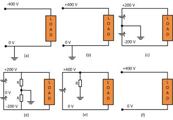
1.Positive line grounding: In this system, the positive line is connected to ground as shown in Figure 6a. This system provides easy detection and breaking of current during a short circuit or earth fault. Monopole breaking is used to break the current. During a fault, the direction of the current through the human heart is upward and the heart-current factor F [39] is twice that of the direct negative grounding system. As a result, it seems like twice the current is flowing through the human body. The current one receives during an electric shock in this type of grounding is the largest among all the grounding systems as the circuit impedance is very low. However, as the fault current is large, it can be interrupted with better accuracy.
2.Negative line grounding: In this type of grounding the negative line is connected to the ground as shown in Figure 6b. The properties of this grounding method are similar to positive line grounding. The current one receives in this type of grounding is usually high, but not as high as positive line grounding.
3.Mid-point line grounding: In this type of grounding, the voltage to grounding is half of that compared to one end grounding as shown in Figure 6c. It is easy to detect and break currents during short circuit and ground faults. The current is usually large when short circuit or earth faults occur on the negative line. When breaking fault current, it is necessary to break both the positive and negative lines at the same time. Usually, rectifiers and batteries implement this type
of grounding and hence they need to deal with higher initial costs.
Energies 2018, 11, x FOR PEER REVIEW |
12 of 21 |
Figure 6. Grounding methods: (apositive) itive line; (b) negative line; (c) mid-poiline;t; (d) midmid-po nt high resistance; (e)
Figure 6. Grounding methods: (a) line; (b) negative (c) -point; (d) mid-point high
one-end high resistance; (f) floating system.
resistance; (e) one-end high resistance; (f) floating system.
5. Reliability
The reliability of both AC and DC systems depends on their system architecture and the level of redundancies. Especially, in DC systems, increasing the system voltage level adversely affects the electrical stresses experienced by the components (switches, breakers, etc.), thereby reducing the reliability of the system. Switching devices like power MOSFETs, IGBTs, diodes, etc. should always be operated within their safe operating area and, hence, are selected considering enough safety margins to take care of the voltage and current transients.
It has been observed that an increase in bus voltages reduces the life of capacitors [46]. The lifetime of electrolytic capacitors is given by