

Sb95651
.pdfМИНОБРНАУКИ РОССИИ
–––––––——————————–––––––
Санкт-Петербургский государственный электротехнический университет «ЛЭТИ» им В.И.Ульянова (Ленина)
————————————————————
V. A. PARFENOV
STUDY OF LASER RADIATION PARAMETERS
Tutorial
Санкт-Петербург Издательство СПбГЭТУ «ЛЭТИ»
2017
УДК 621.373.8(07)
ББК З86-53я7
P 25
Parfenov V. A.
Study of laser radiation parameters: tutorial. St.Petersburg: Publishing house of ETU, 2017. 14 p.
ISBN 978-5-7629-2106-0
Guidelines for 2 laboratory workshops are presented. The workshops are part of laboratory practice on fundamentals of laser technique and fiber-optics. The task of these workshops is study of spatial and energetic characteristics of He-Ne laser as well as main parameters of multimode optical fibers.
The
Guidelines are intended for master students specializing in the
“Instrumentation” area.
УДК 621.373.8(07) ББК З86-53я7
Reviewed by: Department of Quantum Electronics of the St.Petersburg Polytechnic University; Prof. Y.V. Rozhdestvenskii, Doctor of Sciences, Leading Research Fellow, Center for Information Optical Technologies of the National Research University ITMO, St.Petersburg
Утверждено редакционно-издательским советом университета
в качестве учебного пособия
ISBN 978-5-7629-2106-0 |
СПбГЭТУ «ЛЭТИ», 2017 |
Laboratory workshop 1
STUDY OF SPATIAL AND ENERGY CHARACTERISTICS OF HELIUM-NEON LASER
The aim of this laboratory workshop is study of the spatial and energy characteristics of helium-neon laser and receiving skills to work with modern measurement technique designed to analyze them.
1.1.General information
The most important parameters characterizing the spatial and energy characteristics of the laser radiation are divergence and radiation pattern. The purpose of this laboratory workshop is to study these parameters with respect to helium-neon laser. Helium-neon laser is commercially available one due to high stability of its output parameters. It is frequently used, mainly in laser measurement systems.
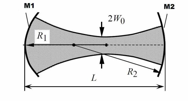
In the study of helium-neon laser one should to keep in the mind features of beam pattern of its radiation associated with use in such a laser optical resonator with spherical mirrors M1 and M2 (see. Figure 1.1).
3 |
Fig. 1.1 |
|
The divergence of radiation of laser, having such configuration of resonator, is determined by its length, the values of the radii of curvature of its mirrors and the lateral dimensions of the active medium. In general, for any laser it depends on transverse distribution of the light field inside the cavity. So-called "zero"-mode (TEM00-mode), corresponding to Gaussian beam, has the minimum value of divergence of radiation. In this case, the divergence angle (the angular width of the radiation pattern) is determined by the following equation:
Q ~ 2λ/(πw0),
where λ - wavelength of the laser, w0 - the radius of smallest cross section of the caustic surface of the electromagnetic light wave (laser beam) in the resonator. It should be remembered that the electromagnetic field in laser resonators creating by spherical mirrors is concentrated in the volume bounded by the caustic surface, beyond which it decreases rapidly. The radius of the smallest cross section of the caustic surface depends on the configuration of the resonator (defined by radii of curvature of mirrors З1 and З2 and the distance L between them).
In practice, measurement of divergence of the radiation and analysis of the light field structure in cross section of the laser beam usually are carried out in the focus of positive lens, because the field intensity distribution in the focal plane corresponds to distributions in the far field. In this case, the beam divergence α can be calculated by the formula:
α ~ D/f, |
(1.1) |
where D - diameter of the spot in the focus of the lens, f - focal length of lens. In recent years, to describe the deviation of the spatial distribution of the laser beam in its section from the distribution corresponding to the so-called Gaussian beam (having a diffraction beam quality), the special parameter, which is called beam quality parameter (another name - М2 parameter) is used.
For laser radiation with diffraction-limited divergence the diameter of light spot in the focus of the lens is given by formula :
doo = 4λf/πDin ,
where doo - the diameter of an ideal Gaussian beam in focus of the lens, λ - the laser wavelength, Din – size of the beam at the lens entrance. Meanwhile, for the
4
real laser beam (i.e. the beam of radiation having divergence exceeding diffraction limit) this formula can be transformed to the following one:
do = 4Mλf/πDin ,
where do – actual beam spot diameter of the laser radiation at the focus of the same lens. Value of M characterizes the increase in the size of the real focal spot of the laser radiation in comparison with the size of the spot of the Gaussian laser beam. Thus, the value М2 indicates how many times the intensity of the radiation of real laser in focus of the lens is less than the radiation intensity of the Gaussian beam at the same conditions. For most lasers, the value М2 is much greater than 1, but in the case of helium-neon lasers, this difference is not so great (the value М2 is very close to 1).
1.2. Description of the laboratory setup
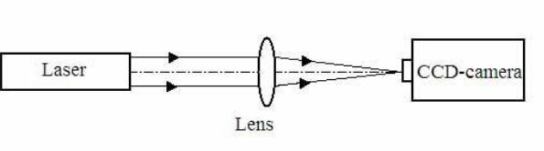
Figure 1.2 shows the optical scheme of the laboratory setup. Radiation of He-Ne laser (wavelength λ = 0,63 mm) is directed (by means of positive lens) to the photosensitive area of CCD camera of the laser beam analyzer. The video output signal from the CCD-camera goes to an oscilloscope. The oscilloscope can detect the distribution of laser beam along two directions (coordinates X and Y).
Fig. 1.2
It should be pointed out that at the moment CCD-camera based laser beam analyzers are very frequently used for analysis of spatial-energy characteristics of radiation of lasers.
General view of the analyzer of the laser beams used in this laboratory workshop is shown in Figure 1.3. Without going into the details of the device description, let us to note that it consists of three main functional units - the video driver, the video signal processing unit and the control unit.
5
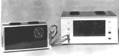
Fig. 1.3.
The main output characteristics of the laser beam analyzer are as follows: Spectral range – 0.4 ... 1.1 micrometers;
Dimensions of a photosensitive matrix of the CCD-camera – 4.6 mm (along coordinate X) and 5.2 mm (coordinate Y);
The number of matrix elements (by X and Y) – 144 × 144.
1.3.Program of work
1. |
Switching-on the |
experimental |
setup |
units and |
its |
preparation for use; |
|||
2. |
Observation of the light field distribution of the laser |
radiation in its cross- |
|||||||
section |
(for |
each |
of |
X |
and |
|
Y |
coordinates); |
|
3. Measurement of radiation divergence at X and Y coordinate.
1.4. Sequencing
1. With the permission of the teacher you have to switch on the laser power supply using the toggle switch "Сеть " and get laser generatio.
CAUTION! The laser power supply unit has a high voltage. IT`s DANGEROUS. Before turning on the laser make sure that all electrical connections jacks pf laser
and the power supply are securely connected to each other. |
|
|
|||||
2. |
Switch-on |
the |
laser |
beam |
analyzer |
and |
oscilloscope. |
3.Make sure that the laser beam hits the photosensitive area of CCD-camera.
4.Proceed to observation of the laser radiation distribution in its cross section on the photosensitive area of the CCD-camera, successively in two coordinates (first X, then Y). To do this, the corresponding key on the front panel of the analyzer must be pressed. Register this distribution by digital photocamera.
5.Carry out the measurement of laser radiation divergence in both coordinates.
To do this, measure the size of the laser beam d on each of coordinates (X and Y)
6

in the focus of the lens. If CCD-camera is installed correctly in focus of lens, the value of d can be determined by measurement of width of the light field distribution l of the laser beam on its image on the oscilloscope screen. Most often such measurements are carried out at the level of 0.7 (70% ) of maximum value of light field distribution registering by laser beam analyzer.
To measure the width of the laser beam pattern once should to take into account the following. At the bottom of the distribution of the light field of the laser beam on the oscilloscope screen one can see the "noise comb", which is a "comb" of illumination pulses from each element of the CCD-camera matrix (see. Figure 1.4).
Fig.1.4.
By measuring the width of this "noise comb» (value Δ) using the grid of the oscilloscope screen in millimeters, one can obtain a conversion factor K of linear dimensions of the distribution of the light field, observing in the in the oscilloscope screen, into actual value of size of focused laser beam on the surface of matrix of the CCD-camera for each of the coordinates:
Kx = /a;
Kу = /b,
7
where a and b are the dimensions of the photosensitive area of matrix of te CCDcamera along coordinates X and Y, respectively (a = 46 mm, b = 52 mm). Knowing the values of Kx and Ky, one can calculate the size of a focused laser beam on the surface of the CCD-camera matrix along each of the coordinates:
dx=Kxlx; dy=Kyly
After that, using formula (1.1), one can determine the divergence of laser beam along each coordinates:
αx ~ dx/f; αy ~ dy/f
NB: Do ask teacher for data on focal length of the lens.
1.5.Report on the laboratory workshop
Report must contain following data: |
|
|
|
|
|||||
1. |
|
Optical |
|
layout |
of |
the |
experimental |
setup. |
|
2. |
|
Mathematical |
|
formulas |
used |
|
for |
calculations. |
|
3. |
Distribution of the light field radiation of helium-neon laser on coordinates X |
||||||||
and |
Y, |
registered |
by |
analyzer |
of |
laser |
beams. |
||
4. |
|
The results of |
the |
measurements of |
laser |
beam |
divergence. |
||
5. Conclusions on work and analysis of the obtained results. |
|
|
|||||||
Literature
1 Weber H. Some historical and technical aspects of beam quality // Opt.Quantum Electron. 1992, Vol.24. P.S861-S864.
2 Width D. et.al. Laser beam width, divergence and beam propagation factor – an international standardization approach // Opt. Quantum Electron. 1992. Vol. 24. P.S993-S1000.
8
Laboratory workshop 2
MEASUREMENT OF PARAMETERS OF OPTICAL FIBER AND STUDY OF EFFICIENCY OF ITS EXCITATION
The purpose of the work is study of the physical principles of light propagation in a multimode gradient optical fibers, the measurement of main parameters and study of impact of input conditions onto the effectiveness of excitation of optical fibers.
2.1General info
Optical fibers are flexible optical devices intended for transportation of laser radiation. The main areas of their application include the transfer of information in fiber-optic communication links and the delivery of laser radiation to the surface of materials (in laser processing applications) and biological objects (in medicine and biology).
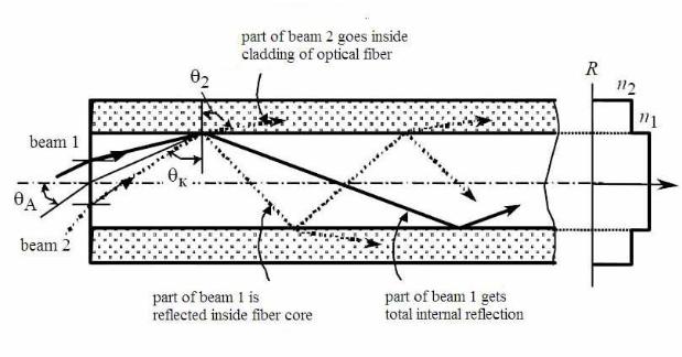
All optical fibers are divided into two main groups: multi-mode fibers and single-mode fibers. The multimode fibers themselves are subdivided into stepped and gradient ones (these names correspond the profile of distribution of refractive index inside the fiber). Figure 2.1 shows the path of the light rays in a stepped fiber.
Fig. 2.1.
9
Each optical fiber consists of two parts - the core and cladding with different refractive indices. All fibers are differed by diameter of core and the cladding, and the refractive index profile of the core.
In comparison with the fiber cladding, its core through which the light signal is spread, is manufactures from optically denser material (i.e. material with a higher refractive index). Let`s denote by n1 and n2 the refractive indices of the core and the cladding, respectively(n1>n2). The propagation of light through the fiber can be explained on the basis of the principle of total internal reflection, arising from the law of Snell for refraction of light. In the most general case the mathematical expression of Snell's law is given by following formula:
n1sinθ1 = n2sinθ2 ,
where n1 - the refractive index of the medium 1, θ1 - angle of incidence, n2 - refractive index of the medium 2, θ2 - the angle of refraction.
Since the core is optically denser medium in relation to the cladding, there is a certain critical angle of incidence θc (the internal angle of incidence of light rays onto the boundary at which the refracted ray goes along borders of core and cladding (θ2=900). The law of Snell's allows to find this critical angle of incidence:
θc= arcsin (n2/n1)
If the angle of incidence on the interface is less than the critical angle (beam 2), then each internal reflection of the energy is dissipated to the outside in the form of a refracted ray, which eventually leads to attenuation of light. If the angle of incidence greater than the critical angle (beam 1), at each reflection from the interface of the core and cladding borders all light energy is returned to the core due to total internal reflection.
Thus, the fiber will propagate only those rays which are incident on the input end of the fiber at angles smaller than the maximum critical angle θA (i.e., the angle at which the light undergoes total internal reflection and propagates along the fiber without losses). This value is dimensionless and is defined by the following formula:
NA = sin θA |
(2.1) |
10