

Sb95668
.pdfМИНОБРНАУКИ РОССИИ
Санкт-Петербургский государственный электротехнический университет «ЛЭТИ» им. В. И. Ульянова (Ленина)
V. Yu. VENEDIKTOV
IMAGING OPTICAL SYSTEMS
Tutorial
Санкт-Петербург Издательство СПбГЭТУ «ЛЭТИ»
2017
УДК 535 (075)
ББК В 34я7 V 38
Venediktov V. Yu.
V 38 Imaging optical systems: Tutorial. SPb.: SPbGETU «LETI» publishers, 2013. 43 p.
ISBN 978-5-7629-2102-2
The fundamentals of the theory of constructing optical images, as well as the principles of constructing and basing the designs of various imaging optical systems – the human eye, telescopes, various microscopes, a camera and various lighting systems are considered.
Tutorial is intended for the preparation of bachelors studying in the field of preparation of instrument making № 12.03.01 «Instrumentation Technology». It can also be useful for students studying in related specialties, and engineering and technical workers in this field of knowledge.
УДК 535 (075)
ББК В 34я7 Reviewed by Department of Optical Information Technologies and Materi-
als of ITMO University; Doctor of Science (Physics and Mathematics), professor I.M.Belousova (S.I. Vavilov State Optical Institute).
Утверждено редакционно-издательским советом университета
в качестве учебного пособия
ISBN 978-5-7629-2102-2 |
© СПбГЭТУ «ЛЭТИ», 2017 |
2
1. Optical image
The optical image is the pattern, produced due to the optical system action onto the optical rays, emitted by the object. Such an image is reproducing the contour of the object and its details. Such a system is usually working either with a humane eye (more specifically, its retina) or with some surface (screen, photosensitive layer or matrix), where the image is positioned.
The best correspondence between the object and its image is observed when each point of the image corresponds to some specific point of the object. In other words, each point of the object emits a bundle of optical rays, and after refraction and reflection at the surfaces of the optical system all these rays are to meet once again at one and the same point of the object. However, it is not always possible. For instance, the system with the axial symmetry (having the so called optical axis) usually provides imaging of only some zone nearby this axis – the so called paraxial zone. Implementation of the geometry optics’ laws makes it possible to determine the position of any image of points from this zone, basing only upon the knowledge of the cardinal points of the system.
The points. which can be imaged by the system, comprise the so-called object space, while the image points comprise the image space. In reality the optical object can be either self-luminous (i.e., emitting optical rays with this or that wavelength) or non-self-luminous. In the latter case it has to be illuminated, and the object is imaged in the scattered light.
One can distinguish the real and the virtual images. The first type is produced by the converging beam of optical rays in the point where they are crossing. Hence, if one positions here the screen he can observe such an image; if he places here the photosensitive layer (e.g., some photographic film) or matrix (e.g., CCDmatrix), he can register the image. The virtual images correspond to the diverging light beams, leaving some optical system; these are the imaginary points, from which the said beam diverges. In this case it is impossible to use the screen or photosensitive layer, but one can use the virtual image as the secondary object for the next optical system or observe it by his eye.
3

1.1. Mirrors
The simplest optical device, providing object imaging, is the plane mirror. Such an image if formed by the rays, reflected by the mirror. This image is a virtual one, since it is produced not by the rays themselves, but by their imaginary continuation (see Fig.1.1). The virtual image is placed symmetrically with respect to the mirror surface, and its size is equal to the size of the very object.
The spherical mirror (see Fig.1.2) is the part of the reflecting surface. The center of such sphere is known as the optical center of the mirror. If the mirror shape is circular,
the center of such a circle is called the mirror pole. The straight line, comprising the mirror center and pole, is called the main optical axis of the mirror. Its only difference from other straight lines, comprising the spherical center, is that it is the mirror axis of symmetry.
Fig.1.2. Parallel beam reflection by the concave spherical mirror. Point O is an optical center, P is a pole, F is the main focus of the mirror, OP is the main optical axis, and R is the mirror
curvature radius.
There are concave and convex spherical mirrors. If there is an optical beam, comprised by the rays which are parallel to the optical axis of the mirror, after reflection the rays will cross in the point, which is called the main focus (focal point) of this mirror F. The distance from this point to the pole is known as the focal
4

length of the mirror and is also denominated as F. The concave mirror has the real focus, which lies at the half-way from the mirror sphere center to the pole. One has to keep in mind, that the parallel beam converges strictly to one single point (focus) only if it is not too wide. in the case of the so-called paraxial beam.
The main focus of the convex mirror is virtual. After reflection from such a mirror the parallel beam converts to the divergent one, and the focus corresponds to the point, where is the imaginary source of this beam (Fig.1.3).
Fig.1.3. Parallel beam reflection by the convex spherical mirror. Point O is an optical center, F is the virtual focus of the mirror, and OP is the main optical axis.
Focal length of the concave mirror is treated usually as the positive value
F = R/2, while that of the convex one – as the negative one F = – R/2, where R is the mirror’s curvature radius. One can construct the image of some point A of the object by spherical mirror with the use of the standard ray pair. One of these rays is the ray AOC, which passes through the optical center of the mirror, and the reflected ray COA belongs to the same straight line. The second ray AFD goes through the mirror focus, and thus the reflected ray is parallel to the axis. One can also use the ray AP, reaching the mirror at its pole; the reflected ray in this case is traced symmetrically to the incident one. One more ray is the ray AE, which is parallel to the main optical axis, and thus the reflected ray EFA1 goes through the mirror focus.
In the Fig.1.4 all the said standard rays are shown for the case of the concave mirror. All these rays pass through the point A', which is an image of the object point A. All other rays, coming from the latter point, are also reflected to the same point A'. Ray tracing, for which all the rays, which were emitted from one point,
5

are then collected also in a single point, is called the stigmatic one. The piece A'B' is thus an image of the piece AB. For the convex mirror the ray tracing is carried out in a similar manner.
Fig.1.4. Imaging by the concave spherical mirror
One can also determine the position of the image and its size with the use of the spherical mirror formula:
1 |
+ |
1 |
= |
1 |
. |
(1.1) |
|
|
|
||||
d f F |
|
|||||
Here d is the distance from the object to the mirror, and f is the distance from the mirror to the image. There is a definite sign rule: for the real objects and for real images d > 0 и f > 0, while for the virtual objects and virtual images is valid d < 0
и f < 0. For the case, shown in the Fig.1.4, we have F > 0 (the mirror is concave); d = 3F > 0 (the real object). The spherical mirror formula provides that
f = 3F/2 > 0, and hence the image is a real one. Imagine we have replaced the concave mirror by the convex one, staying in the same place and having the same modulus of its focal length. In this case we should have had F < 0, d = – 3F > 0, and f = 3F/4 < 0, corresponding to the virtual image.
The linear magnification of the spherical mirror Γ is determined as the ratio of the linear size of the image h' to that of the object h. It is convenient to treat the value as the positive one if the image is non-inverted (h' > 0), and as the negative one for the inverted image (h' < 0). The value of h is always positive. In this case one can easily derive from the Fig.1.4 the formula for the magnification Γ = h’/h = – f/d. We have considered two cases. In the first one Γ = – 1/2 < 0, and thus the image is an inverted one and its scale is reduced in 2 times. In the second case Γ = 1/4 > 0, and thus the image is non-inverted and is reduced in 4 times.
6
1.2. Thin lens
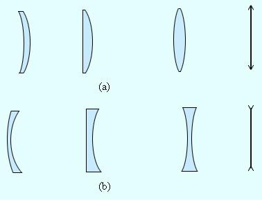
The lens is the transparent body, limited by two spherical surfaces. If its thickness is much less than the curvature radiuses of both surfaces, such a lens is known as a thin lens. Nearly all optical devices have lenses in them. There exists the positive (converging) and negative (diverging) lenses. The positive lens has the largest thickness at its central zone, while the negative – vice versa (see Fig.1.5).
Fig.1.5. Converging (a) and diverging (b) lenses and their conventional depiction
The straight line, comprising the curvature centers of both spherical surfaces
O1 and O2, is known as the main optical axis of the lens or just its axis. In the case of a thin lens one can say that the main axis crosses the lens in one point, which is known as the lens center O. All optical rays pass through the lens center without deviation from their primary direction. Straight lines, crossing the lens in this center, are sometimes called the auxiliary or ollateral optical axes. The bundle of optical rays, parallel to the main axis of the lens (the so-called parallel optical beam), will be collected by the converging lens in one point F, which is known as the main focus (focal point) of the lens. In the case of diverging lens, the beam will be diverging from the imaginary point beyond the lens, having the same name. Hence the converging lenses have the real focuses, while the diverging one – virtual. Thin lens has to focuses, lying on its optical axis symmetrically with regard to the lens. Optical beams, which are parallel to the ollateral optical axes, are focused to some points F’ (ollateral foci or focuses) belonging to the so-called focal plane Φ, perpendicular to the main axis and comprising the point F (see Fig.1.6). The distance between the lens center O and the main focus F is known as the focal distance of the lens and is also denoted F.
7

Fig.1.6. Refraction of the parallel optical beam by the converging (a) and diverging (b) lenses. The points O1 and O2 correspond to the centers of spherical surfaces, limiting the lens, , O is the optical center, F is the main focus and F' are the ollateral foci, , OF' is the ollateral axis, and Ф is the focal plane
The main property of lenses is their ability to image optical objects. There are possible the inverted and non-inverted, real and virtual, magnified and reduced images. One can evaluate the image position and its character by means of geometry ray tracing, using the tracing of several standard rays with the pre-known traces. These are the rays, crossing the optical center or one of lenses foci, as well as the rays, which are parallel to the main or ollateral axes of the lens. One can see the examples of such tracing in the Figures 1.7 and 1.8.
One can also evaluate the image position and its nature (real or virtual) with the use of the thin lens formula:
1 |
+ |
1 |
= |
1 |
= D . |
(1.2) |
|
|
|
||||
d f F |
|
|||||
Here d is the distance from the object to the lens, and f is the distance from the lens to the image. The value D, which is equal to 1/F, is known as the optical power of the lens. It is measured in diopters, 1 dpt ≡ 1 m-1. One can see that the thin lens formula is very similar to the spherical lens formula. One can derive it for the paraxial rays from geometrical treatment, using the similarity of triangles in the Figures 1.7 and 1.8.
8
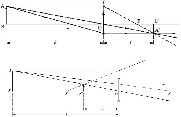
Fig.1.7. Imaging by the converging lens
Fig.1.8. Imaging by the diverging lens
The variables in this formula have definite signs. For the converging lens the values of focal distance are treated as positive F > 0, while for the diverging F < 0. For the real object and for real images the values d > 0 and f > 0, while for virtual d < 0 и f < 0. So for the case, shown in the Fig.1.7, we have F > 0 (the lens is converging) and d = 3F > 0 (the real object). From the thin lens formula we thus obtain f = 3F/2 > 0, and thus the image is also real. For the case, shown in the Fig.1.8, we have F < 0 (the lens is diverging) and d = 2|F| > 0 (the object is real), and thus the image is virtual – f = – 2 F/3 < 0.
The scale of the image depends upon the object position with respect to the lens. The linear magnification of the lens Γ is determined as the ratio of the linear size of the image h' to that of the object h, and the sign rules are the same as for the mirror case. Hence for the non-inverted images Γ > 0, and for inverted ones Γ < 0. The formula for the linear magnification of the thin lens Γ = h’/ h = – f/d can be easily derived from the triangles similarity in the Figures 1.7 and 1.8.
In the above considered example with the converging lens (Fig.1.7) there is d = 3F > 0, f = 3F/2 > 0, and hence Γ = – 1/2 < 0, i.e. the image is inverted and its scale is reduced in 2 times. For the diverging lens case, shown in the
9
Fig.1.8,: d = 2|F| > 0, f = – 2| F|/3 < 0, and thus Γ = 1/3 > 0 – i.e. the image is noninverted and its scale is reduced in 3 times.
The optical power of the lens D depends upon the curvature radiuses of its surfaces R1 and R2 and upon the refraction index of its material n. In optical textbooks there is derived the following formula:
|
1 |
|
1 |
|
1 |
|
|
D = |
|
= (n −1) |
|
+ |
|
|
(1.3) |
|
|
|
|||||
|
F |
|
|
|
|
|
|
|
R1 |
|
R2 |
|
|||
For the first convex surface the curvature radius is treated as positive value, and for the second one – as negative; for the concave surfa ces – vice versa. The account for the real lens thickness d provides the more accurate thick lens formula:
|
1 |
|
1 |
|
1 |
|
|
(n −1) |
2 |
|
|
D = |
|
= (n −1) |
|
+ |
|
|
+ |
|
|
d . |
(1.4) |
|
|
|
|
|
|||||||
|
F |
|
|
|
|
|
|
nR1R2 |
|
||
|
R1 |
|
R2 |
|
|
||||||
In the majority of optical systems (optical devices) the light passes through the series of several lenses and can be also reflected by one or several plane or non-plane mirrors. The image of the primary object, constructed by the first lens (mirror) becomes the secondary object (real or virtual) for the next lens and so on. For example, if one wants to calculate the action of the system, comprised by two thin lenses, he has to implement twice the thin lens formula. The distance from the primary image to the second lens d2 is in this case equal to l – f1, where l is the distance between lenses. One can thus evaluate the distance to the second image f2 and its nature – is it real ( f2 > 0) or virtual (f2 < 0). The general magnification of the system Γ is evaluated as the product of two magnifications Γ = Γ1 · Γ2. Some optical systems (telescopes and microscopes) are working with either the infinitely distant object of image. In these cases the linear magnification has no physical sense and there are used the so-called angular magnification (when both the object and image are at infinity) or generalized magnification.
1.3. Point spread function
The point spread function (PSF) describes the distribution of light intensity in the image of a point object. Since this image has the finite transverse size, it is called the spot, and the image of some object, comprised by points, is comprised by the light spots. produced by action of optical system onto each of these points. For the ideal optical system the PSF is symmetrical with regard to the optical axis. It comprises the central maximum (the so-called Airy disk, whose diameter is
10