

- •1 Scope
- •1.1 General
- •2 Conformance
- •2.1 General
- •2.2 Process Modeling Conformance
- •2.2.1 BPMN Process Types
- •2.2.2 BPMN Process Elements
- •Descriptive Conformance Sub-Class
- •Analytic Conformance Sub-Class
- •Common Executable Conformance Sub-Class
- •2.2.3 Visual Appearance
- •2.2.4 Structural Conformance
- •2.2.5 Process Semantics
- •2.2.6 Attributes and Model Associations
- •2.2.7 Extended and Optional Elements
- •2.2.8 Visual Interchange
- •2.3 Process Execution Conformance
- •2.3.1 Execution Semantics
- •2.3.2 Import of Process Diagrams
- •2.4 BPEL Process Execution Conformance
- •2.5 Choreography Modeling Conformance
- •2.5.1 BPMN Choreography Types
- •2.5.2 BPMN Choreography Elements
- •2.5.3 Visual Appearance
- •2.5.4 Choreography Semantics
- •2.5.5 Visual Interchange
- •2.6 Summary of BPMN Conformance Types
- •3 Normative References
- •3.1 General
- •3.2 Normative
- •3.3 Non-Normative
- •Activity Service
- •BPEL4People
- •Business Process Definition Metamodel
- •Business Process Modeling
- •Business Transaction Protocol
- •Dublin Core Meta Data
- •ebXML BPSS
- •Open Nested Transactions
- •SOAP 1.2
- •UDDI
- •WfMC Glossary
- •Web Services Transaction
- •Workflow Patterns
- •WSBPEL
- •WS-Coordination
- •WSDL
- •WS-HumanTask
- •XML 1.0 (Second Edition)
- •XML-Namespaces
- •XML-Schema
- •XPath
- •XPDL
- •4 Terms and Definitions
- •5 Symbols
- •6 Additional Information
- •6.1 Conventions
- •6.1.1 Typographical and Linguistic Conventions and Style
- •6.1.2 Abbreviations
- •6.2 Structure of this Document
- •6.3 Acknowledgments
- •Submitting Organizations
- •Supporting Organizations
- •Special Acknowledgments
- •7 Overview
- •7.1 General
- •7.2 BPMN Scope
- •7.2.1 Uses of BPMN
- •Private (Internal) Business Processes
- •Public Processes
- •Collaborations
- •Choreographies
- •Conversations
- •Diagram Point of View
- •Understanding the Behavior of Diagrams
- •7.3 BPMN Elements
- •7.3.1 Basic BPMN Modeling Elements
- •7.3.2 Extended BPMN Modeling Elements
- •7.4 BPMN Diagram Types
- •7.5 Use of Text, Color, Size, and Lines in a Diagram
- •7.6 Flow Object Connection Rules
- •7.6.1 Sequence Flow Connections Rules
- •7.6.2 Message Flow Connection Rules
- •7.7 BPMN Extensibility
- •7.8 BPMN Example
- •8 BPMN Core Structure
- •8.1 General
- •8.2 Infrastructure
- •8.2.1 Definitions
- •8.2.2 Import
- •8.2.3 Infrastructure Package XML Schemas
- •8.3 Foundation
- •8.3.1 Base Element
- •8.3.2 Documentation
- •8.3.3 Extensibility
- •Extension
- •ExtensionDefinition
- •ExtensionAttributeDefinition
- •ExtensionAttributeValue
- •Extensibility XML Schemas
- •XML Example
- •8.3.4 External Relationships
- •8.3.5 Root Element
- •8.3.6 Foundation Package XML Schemas
- •8.4 Common Elements
- •8.4.1 Artifacts
- •Common Artifact Definitions
- •Artifact Sequence Flow Connections
- •Artifact Message Flow Connections
- •Association
- •Group
- •Category
- •Text Annotation
- •XML Schema for Artifacts
- •8.4.2 Correlation
- •CorrelationKey
- •Key-based Correlation
- •Context-based Correlation
- •XML Schema for Correlation
- •8.4.3 Error
- •8.4.4 Escalation
- •8.4.5 Events
- •8.4.6 Expressions
- •Expression
- •Formal Expression
- •8.4.7 Flow Element
- •8.4.8 Flow Elements Container
- •8.4.9 Gateways
- •8.4.10 Item Definition
- •8.4.11 Message
- •8.4.12 Resources
- •8.4.13 Sequence Flow
- •Flow Node
- •8.4.14 Common Package XML Schemas
- •8.5 Services
- •8.5.1 Interface
- •8.5.2 EndPoint
- •8.5.3 Operation
- •8.5.4 Service Package XML Schemas
- •9 Collaboration
- •9.1 General
- •9.2 Basic Collaboration Concepts
- •9.2.1 Use of BPMN Common Elements
- •9.3 Pool and Participant
- •9.3.1 Participants
- •PartnerEntity
- •PartnerRole
- •Participant Multiplicity
- •ParticipantAssociation
- •9.3.2 Lanes
- •9.4 Message Flow
- •9.4.1 Interaction Node
- •9.4.2 Message Flow Associations
- •9.5 Conversations
- •9.5.1 Conversation Node
- •9.5.2 Conversation
- •9.5.3 Sub-Conversation
- •9.5.4 Call Conversation
- •9.5.5 Global Conversation
- •9.5.6 Conversation Link
- •9.5.7 Conversation Association
- •9.5.8 Correlations
- •9.6 Process within Collaboration
- •9.7 Choreography within Collaboration
- •9.8 Collaboration Package XML Schemas
- •10 Process
- •10.1 General
- •10.2 Basic Process Concepts
- •10.2.1 Types of BPMN Processes
- •10.2.2 Use of BPMN Common Elements
- •10.3 Activities
- •Sequence Flow Connections
- •Message Flow Connections
- •10.3.1 Resource Assignment
- •Resource Role
- •Expression Assignment
- •Parameterized Resource Assignment
- •10.3.2 Performer
- •10.3.3 Tasks
- •Service Task
- •Send Task
- •Receive Task
- •User Task
- •Manual Task
- •Business Rule
- •Script Task
- •10.3.4 Human Interactions
- •Notation
- •Manual Task
- •User Task
- •Rendering of User Tasks
- •Human Performers
- •Potential Owners
- •XML Schema for Human Interactions
- •Examples
- •10.3.5 Sub-Processes
- •Embedded Sub-Process (Sub-Process)
- •Reusable Sub-Process (Call Activity)
- •Event Sub-Process
- •Transaction
- •Ad-Hoc Sub-Process
- •10.3.6 Call Activity
- •Callable Element
- •10.3.7 Global Task
- •Types of Global Task
- •10.3.8 Loop Characteristics
- •Standard Loop Characteristics
- •Multi-Instance Characteristics
- •Complex Behavior Definition
- •10.3.9 XML Schema for Activities
- •10.4 Items and Data
- •10.4.1 Data Modeling
- •Item-Aware Elements
- •Data Objects
- •DataObject
- •States
- •Data Objects representing a Collection of Data
- •Visual representations of Data Objects
- •Lifecycle and Accessibility
- •Data Stores
- •Properties
- •Lifecycle and Accessibility
- •Data Inputs and Outputs
- •Data Input
- •States
- •Data Output
- •States
- •Service Task Mapping
- •Send Task Mapping
- •Receive Task Mapping
- •User Task Mapping
- •Call Activity Mapping
- •Script Task Mapping
- •Events
- •InputSet
- •OutputSet
- •Data Associations
- •DataAssociation
- •Assignment
- •DataInputAssociation
- •DataOutputAssociation
- •Data Objects associated with a Sequence Flow
- •10.4.2 Execution Semantics for Data
- •Execution Semantics for DataAssociation
- •10.4.3 Usage of Data in XPath Expressions
- •Access to BPMN Data Objects
- •Access to BPMN Data Input and Data Output
- •Access to BPMN Properties
- •For BPMN Instance Attributes
- •10.4.4 XML Schema for Data
- •10.5 Events
- •10.5.1 Concepts
- •Data Modeling and Events
- •Common Event attributes
- •Common Catch Event attributes
- •Common Throw Event Attributes
- •Implicit Throw Event
- •10.5.2 Start Event
- •Start Event Triggers
- •Start Events for Top-level Processes
- •Start Events for Sub-Processes
- •Start Events for Event Sub-Processes
- •Attributes for Start Events
- •Sequence Flow Connections
- •Message Flow Connections
- •10.5.3 End Event
- •End Event Results
- •Sequence Flow Connections
- •Message Flow Connections
- •10.5.4 Intermediate Event
- •Intermediate Event Triggers
- •Intermediate Events in Normal Flow
- •Intermediate Events Attached to an Activity Boundary
- •Attributes for Boundary Events
- •Activity Boundary Connections
- •Sequence Flow Connections
- •Message Flow Connections
- •10.5.5 Event Definitions
- •Event Definition Metamodel
- •Cancel Event
- •Compensation Event
- •Conditional Event
- •Error Event
- •Escalation Event Definition
- •Link Event Definition
- •Message Event Definition
- •Multiple Event
- •None Event
- •Parallel Multiple Event
- •Signal Event
- •Terminate Event
- •Timer Event
- •10.5.6 Handling Events
- •Handling Start Events
- •Handling Events within normal Sequence Flow (Intermediate Events)
- •Handling Events attached to an Activity (Intermediate boundary Events and Event Sub-Processes)
- •Interrupting Event Handlers (Error, Escalation, Message, Signal, Timer, Conditional, Multiple, and Parallel Multiple)
- •Non-interrupting Event Handlers (Escalation, Message, Signal, Timer, Conditional, Multiple, and Parallel Multiple)
- •Handling End Events
- •10.5.7 Scopes
- •10.5.8 Events Package XML Schemas
- •10.6 Gateways
- •10.6.1 Sequence Flow Considerations
- •10.6.2 Exclusive Gateway
- •10.6.3 Inclusive Gateway
- •10.6.4 Parallel Gateway
- •10.6.5 Complex Gateway
- •10.6.6 Event-Based Gateway
- •10.6.7 Gateway Package XML Schemas
- •10.7 Compensation
- •10.7.1 Compensation Handler
- •10.7.2 Compensation Triggering
- •10.7.3 Relationship between Error Handling and Compensation
- •10.8 Lanes
- •10.9 Process Instances, Unmodeled Activities, and Public Processes
- •10.10 Auditing
- •10.11 Monitoring
- •10.12 Process Package XML Schemas
- •11 Choreography
- •11.1 General
- •11.2 Basic Choreography Concepts
- •11.3 Data
- •11.4 Use of BPMN Common Elements
- •11.4.1 Sequence Flow
- •11.4.2 Artifacts
- •11.5 Choreography Activities
- •11.5.1 Choreography Task
- •11.5.2 Sub-Choreography
- •The Parent Sub-Choreography (Expanded)
- •11.5.3 Call Choreography
- •11.5.4 Global Choreography Task
- •11.5.5 Looping Activities
- •11.5.6 The Sequencing of Activities
- •11.6 Events
- •11.6.1 Start Events
- •11.6.2 Intermediate Events
- •11.6.3 End Events
- •11.7 Gateways
- •11.7.1 Exclusive Gateway
- •11.7.2 Event-Based Gateway
- •11.7.3 Inclusive Gateway
- •11.7.4 Parallel Gateway
- •11.7.5 Complex Gateway
- •11.7.6 Chaining Gateways
- •11.8 Choreography within Collaboration
- •11.8.1 Participants
- •11.8.2 Swimlanes
- •Choreography Task in Combined View
- •Sub-Choreography in Combined View
- •11.9 XML Schema for Choreography
- •12 BPMN Notation and Diagrams
- •12.1 BPMN Diagram Interchange (BPMN DI)
- •12.1.1 Scope
- •12.1.2 Diagram Definition and Interchange
- •12.1.3 How to Read this Clause
- •12.2 BPMN Diagram Interchange (DI) Meta-model
- •12.2.1 Overview
- •12.2.2 Abstract Syntax
- •12.2.3 Classifier Descriptions
- •12.2.4 Complete BPMN DI XML Schema
- •12.3 Notational Depiction Library and Abstract Element Resolutions
- •12.3.1 Labels
- •12.3.2 BPMNShape
- •Markers for Activities
- •Tasks [BPMNShape]
- •Collapsed Sub-Processes [BPMNShape]
- •Expanded Sub-Processes [BPMNShape]
- •Collapsed Ad Hoc Sub-Processes [BPMNShape]
- •Expanded Ad Hoc Sub-Processes [BPMNShape]
- •Collapsed Transactions [BPMNShape]
- •Expanded Transactions [BPMNShape]
- •Collapsed Event Sub-Processes [BPMNShape]
- •Expanded Event Sub-Processes [BPMNShape]
- •Call Activities (Calling a Global Task) [BPMNShape]
- •Collapsed Call Activities (Calling a Process) [BPMNShape]
- •Expanded Call Activities (Calling a Process) [BPMNShape]
- •Data [BPMNShape]
- •Events [BPMNShape]
- •Gateways [BPMNShape]
- •Artifacts [BPMNShape]
- •Lanes [BPMNShape]
- •Pools [BPMNShape]
- •Choreography Tasks [BPMNShape]
- •Collapsed Sub-Choreographies [BPMNShape]
- •Expanded Sub-Choreographies [BPMNShape]
- •Call Choreographies (Calling a Global Choreography Task) [BPMNShape]
- •Collapsed Call Choreographies (Calling a Choreography) [BPMNShape]
- •Expanded Call Choreographies (Calling a Choreography) [BPMNShape]
- •Choreography Participant Bands [BPMNShape]
- •Conversations [BPMNShape]
- •12.3.3 BPMNEdge
- •Connecting Objects [BPMNEdge]
- •12.4 Example(s)
- •12.4.1 Depicting Content in a Sub-Process
- •Expanded Sub-Process
- •Expanded Sub-Process with Start and End Events on Border
- •Collapsed Sub-Process
- •12.4.2 Multiple Lanes and Nested Lanes
- •12.4.3 Vertical Collaboration
- •12.4.4 Conversation
- •12.4.5 Choreography
- •13 BPMN Execution Semantics
- •13.1 General
- •13.2 Process Instantiation and Termination
- •13.3 Activities
- •13.3.1 Sequence Flow Considerations
- •13.3.2 Activity
- •13.3.3 Task
- •13.3.4 Sub-Process/Call Activity
- •13.3.5 Ad-Hoc Sub-Process
- •Operational semantics
- •13.3.6 Loop Activity
- •13.3.7 Multiple Instances Activity
- •13.4 Gateways
- •13.4.1 Parallel Gateway (Fork and Join)
- •13.4.2 Exclusive Gateway (Exclusive Decision (data-based) and Exclusive Merge)
- •13.4.3 Inclusive Gateway (Inclusive Decision and Inclusive Merge)
- •13.4.4 Event-based Gateway (Exclusive Decision (event-based))
- •13.4.5 Complex Gateway (related to Complex Condition and Complex Merge)
- •13.5 Events
- •13.5.1 Start Events
- •13.5.2 Intermediate Events
- •13.5.3 Intermediate Boundary Events
- •13.5.4 Event Sub-Processes
- •Operational semantics
- •13.5.5 Compensation
- •Compensation Handler
- •Compensation Triggering
- •Relationship between Error Handling and Compensation
- •Operational Semantics
- •13.5.6 End Events
- •Process level end events
- •Sub-process level end events
- •14 Mapping BPMN Models to WS-BPEL
- •14.1 General
- •14.2 Basic BPMN-BPEL Mapping
- •14.2.1 Process
- •14.2.2 Activities
- •Common Activity Mappings
- •Task Mappings
- •Service Task
- •Receive Task
- •Send Task
- •Abstract Task
- •Service Package
- •Message
- •Interface and Operation
- •Conversations and Correlation
- •Sub-Process Mappings
- •Mapping of Event Sub-Processes
- •Activity Loop Mapping
- •Standard Loops
- •Dealing with LoopMaximum
- •Multi-Instance Activities
- •14.2.3 Events
- •Start Event Mappings
- •Message Start Events
- •Error Start Events
- •Compensation Start Events
- •Intermediate Event Mappings (Non-boundary)
- •Message Intermediate Events (Non-boundary)
- •Timer Intermediate Events (Non-boundary)
- •Compensation Intermediate Events (Non-boundary)
- •End Event Mappings
- •None End Events
- •Message End Events
- •Error End Events
- •Compensation End Events
- •Terminate End Events
- •Boundary Intermediate Events
- •Message Boundary Events
- •Error Boundary Events
- •Compensation Boundary Events
- •Multiple Boundary Events, and Boundary Events with Loops
- •14.2.4 Gateways and Sequence Flows
- •Exclusive (Data-based) Decision Pattern
- •Exclusive (Event-based) Decision Pattern
- •Inclusive Decision Pattern
- •Parallel Pattern
- •Sequence Pattern
- •Structured Loop Patterns
- •Handling Loops in Sequence Flows
- •14.2.5 Handling Data
- •Data Objects
- •Properties
- •Input and Output Sets
- •Data Associations
- •Expressions
- •Assignments
- •14.3 Extended BPMN-BPEL Mapping
- •14.3.1 End Events
- •14.3.2 Loop/Switch Combinations From a Gateway
- •14.3.3 Interleaved Loops
- •14.3.4 Infinite Loops
- •14.3.5 BPMN Elements that Span Multiple WSBPEL Sub-Elements
- •15 Exchange Formats
- •15.1 Interchanging Incomplete Models
- •15.2 Machine Readable Files
- •15.3.1 Document Structure
- •15.3.2 References within the BPMN XSD
- •15.5 XSLT Transformation between XSD and XMI
- •B.1 Scope
- •B.2 Architecture
- •B.3 Diagram Common
- •B.3.1 Overview
- •B.3.2 Abstract Syntax
- •B.3.3 Classifier Descriptions
- •B.4 Diagram Interchange
- •B.4.1 Overview
- •B.4.2 Abstract Syntax
- •B.4.3 Classifier Descriptions
triggers compensation for all instances within the current scope. If compensation is specified via a boundary compensation handler, this boundary compensation handler also is invoked once for each instance of the Multi-Instance Sub-Process in the current scope.
10.7.3 Relationship between Error Handling and Compensation
The following items define the relationship between error handling and compensation:
•Compensation employs a “presumed abort principle,” with the following consequences: Compensation of a failed Activity results in a null operation.
•When an Activity fails, i.e., is left because an error has been thrown, it’s the error handlers responsibility to ensure that no further compensation will be necessary once the error handler has completed.
•If no error Event Sub-Process is specified for a particular Sub-Process and a particular error, the default behavior is to automatically call compensation for all contained Activities of that Sub-Process if that error is thrown, ensuring the behavior for auditing and monitoring.
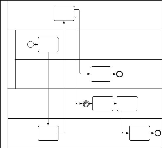
10.8 Lanes
A Lane is a sub-partition within a Process (often within a Pool) and will extend the entire length of the Process level, either vertically (see Figure 10.122) or horizontally (see Figure 10.123). Text associated with the Lane (e.g., its name and/or that of any Process element attribute) can be placed inside the shape, in any direction or location, depending on the preference of the modeler or modeling tool vendor. Our examples place the name as a banner on the left side (for horizontal Pools) or at the top (for vertical Pools) on the other side of the line that separates the Pool name, however, this is not a requirement.
A Lane is a square-cornered rectangle that MUST be drawn with a solid single line (see Figure 10.123 and Figure 10.124).
The label for the Lane MAY be placed in any location and direction within the Lane, but MUST NOT be separated from the contents of the Lane by a single line (except in the case that there are sub-Lanes within the Lane).
304 |
Business Process Model and Notation (BPMN), v2.0.2 |

Name
Name Name
Figure 10.123 – Two Lanes in a Vertical Pool
Name N ame
Name
Figure 10.124 – Two Lanes in a horizontal Pool
Lanes are used to organize and categorize Activities within a Pool. The meaning of the Lanes is up to the modeler. BPMN does not specify the usage of Lanes. Lanes are often used for such things as internal roles (e.g., Manager, Associate), systems (e.g., an enterprise application), an internal department (e.g., shipping, finance), etc. In addition, Lanes can be nested (see Figure 10.125) or defined in a matrix. For example, there could be an outer set of Lanes for company departments and then an inner set of Lanes for roles within each department.
Business Process Model and Notation (BPMN), v2.0.2 |
305 |
|
Sales |
|
Sell to |
|
|
|
Customer |
|
|
|
|
|
|
|
|
|
-Sales |
Accumulate |
|
|
|
Require- |
|
|
|
|
Pre |
ments |
|
|
Marketing |
|
|
|
Supplier |
Post-Sales |
Verify |
|
|
Require- |
|
|||
ments |
|
|||
|
|
|||
|
Consulting |
|
Consulting |
Bugs |
|
|
Required |
Diagnosed |
|
|
|
Bug List |
|
|
|
Engineering |
|
Develop |
Develop |
|
|
Product |
Patch |
|
|
|
|
|
Figure 10.125 – An Example of Nested Lanes
Figure 10.126 shows the Lane class diagram. When a Lane is defined it is contained within a LaneSet, which is contained within a Process.
306 |
Business Process Model and Notation (BPMN), v2.0.2 |
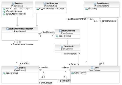
Figure 10.126 – The Lane class diagram
The LaneSet element defines the container for one or more Lanes. A Process can contain one or more LaneSets. Each LaneSet and its Lanes can partition the Flow Nodes in a different way.
The LaneSet element inherits the attributes and model associations of BaseElement (see Table 8.5). Table 10.134 presents the additional attributes and model associations of the LaneSet element.
Table 10.134 – LaneSet attributes and model associations
Attribute Name |
Description/Usage |
|
|
name: sting [0..1] |
The name of the LaneSet. A LaneSet is not visually displayed on a BPMN |
|
diagram. Consequently, the name of the LaneSet is not displayed as well. |
process: Process |
The Process owning the LaneSet |
|
|
lanes: Lane [0..*] |
One or more Lane elements, which define a specific partition in the LaneSet. |
|
|
parentLane: Lane [0..1] |
The reference to a Lane element which is the parent of this LaneSet. |
|
A Lane element defines one specific partition in a LaneSet. The Lane can define a partition element that specifies the value and element type, a tool can use to determine the list of Flow Nodes to be partitioned into this Lane. All Lanes in a single LaneSet MUST define partition element of the same type, e.g., all Lanes in a LaneSet reference a Resource as the partition element, but each Lane references a different Resource instance.
The Lane element inherits the attributes and model associations of BaseElement (see Table 8.5). Table 10.135 presents the additional attributes and model associations of the Lane element.
Business Process Model and Notation (BPMN), v2.0.2 |
307 |