

- •1 Scope
- •1.1 General
- •2 Conformance
- •2.1 General
- •2.2 Process Modeling Conformance
- •2.2.1 BPMN Process Types
- •2.2.2 BPMN Process Elements
- •Descriptive Conformance Sub-Class
- •Analytic Conformance Sub-Class
- •Common Executable Conformance Sub-Class
- •2.2.3 Visual Appearance
- •2.2.4 Structural Conformance
- •2.2.5 Process Semantics
- •2.2.6 Attributes and Model Associations
- •2.2.7 Extended and Optional Elements
- •2.2.8 Visual Interchange
- •2.3 Process Execution Conformance
- •2.3.1 Execution Semantics
- •2.3.2 Import of Process Diagrams
- •2.4 BPEL Process Execution Conformance
- •2.5 Choreography Modeling Conformance
- •2.5.1 BPMN Choreography Types
- •2.5.2 BPMN Choreography Elements
- •2.5.3 Visual Appearance
- •2.5.4 Choreography Semantics
- •2.5.5 Visual Interchange
- •2.6 Summary of BPMN Conformance Types
- •3 Normative References
- •3.1 General
- •3.2 Normative
- •3.3 Non-Normative
- •Activity Service
- •BPEL4People
- •Business Process Definition Metamodel
- •Business Process Modeling
- •Business Transaction Protocol
- •Dublin Core Meta Data
- •ebXML BPSS
- •Open Nested Transactions
- •SOAP 1.2
- •UDDI
- •WfMC Glossary
- •Web Services Transaction
- •Workflow Patterns
- •WSBPEL
- •WS-Coordination
- •WSDL
- •WS-HumanTask
- •XML 1.0 (Second Edition)
- •XML-Namespaces
- •XML-Schema
- •XPath
- •XPDL
- •4 Terms and Definitions
- •5 Symbols
- •6 Additional Information
- •6.1 Conventions
- •6.1.1 Typographical and Linguistic Conventions and Style
- •6.1.2 Abbreviations
- •6.2 Structure of this Document
- •6.3 Acknowledgments
- •Submitting Organizations
- •Supporting Organizations
- •Special Acknowledgments
- •7 Overview
- •7.1 General
- •7.2 BPMN Scope
- •7.2.1 Uses of BPMN
- •Private (Internal) Business Processes
- •Public Processes
- •Collaborations
- •Choreographies
- •Conversations
- •Diagram Point of View
- •Understanding the Behavior of Diagrams
- •7.3 BPMN Elements
- •7.3.1 Basic BPMN Modeling Elements
- •7.3.2 Extended BPMN Modeling Elements
- •7.4 BPMN Diagram Types
- •7.5 Use of Text, Color, Size, and Lines in a Diagram
- •7.6 Flow Object Connection Rules
- •7.6.1 Sequence Flow Connections Rules
- •7.6.2 Message Flow Connection Rules
- •7.7 BPMN Extensibility
- •7.8 BPMN Example
- •8 BPMN Core Structure
- •8.1 General
- •8.2 Infrastructure
- •8.2.1 Definitions
- •8.2.2 Import
- •8.2.3 Infrastructure Package XML Schemas
- •8.3 Foundation
- •8.3.1 Base Element
- •8.3.2 Documentation
- •8.3.3 Extensibility
- •Extension
- •ExtensionDefinition
- •ExtensionAttributeDefinition
- •ExtensionAttributeValue
- •Extensibility XML Schemas
- •XML Example
- •8.3.4 External Relationships
- •8.3.5 Root Element
- •8.3.6 Foundation Package XML Schemas
- •8.4 Common Elements
- •8.4.1 Artifacts
- •Common Artifact Definitions
- •Artifact Sequence Flow Connections
- •Artifact Message Flow Connections
- •Association
- •Group
- •Category
- •Text Annotation
- •XML Schema for Artifacts
- •8.4.2 Correlation
- •CorrelationKey
- •Key-based Correlation
- •Context-based Correlation
- •XML Schema for Correlation
- •8.4.3 Error
- •8.4.4 Escalation
- •8.4.5 Events
- •8.4.6 Expressions
- •Expression
- •Formal Expression
- •8.4.7 Flow Element
- •8.4.8 Flow Elements Container
- •8.4.9 Gateways
- •8.4.10 Item Definition
- •8.4.11 Message
- •8.4.12 Resources
- •8.4.13 Sequence Flow
- •Flow Node
- •8.4.14 Common Package XML Schemas
- •8.5 Services
- •8.5.1 Interface
- •8.5.2 EndPoint
- •8.5.3 Operation
- •8.5.4 Service Package XML Schemas
- •9 Collaboration
- •9.1 General
- •9.2 Basic Collaboration Concepts
- •9.2.1 Use of BPMN Common Elements
- •9.3 Pool and Participant
- •9.3.1 Participants
- •PartnerEntity
- •PartnerRole
- •Participant Multiplicity
- •ParticipantAssociation
- •9.3.2 Lanes
- •9.4 Message Flow
- •9.4.1 Interaction Node
- •9.4.2 Message Flow Associations
- •9.5 Conversations
- •9.5.1 Conversation Node
- •9.5.2 Conversation
- •9.5.3 Sub-Conversation
- •9.5.4 Call Conversation
- •9.5.5 Global Conversation
- •9.5.6 Conversation Link
- •9.5.7 Conversation Association
- •9.5.8 Correlations
- •9.6 Process within Collaboration
- •9.7 Choreography within Collaboration
- •9.8 Collaboration Package XML Schemas
- •10 Process
- •10.1 General
- •10.2 Basic Process Concepts
- •10.2.1 Types of BPMN Processes
- •10.2.2 Use of BPMN Common Elements
- •10.3 Activities
- •Sequence Flow Connections
- •Message Flow Connections
- •10.3.1 Resource Assignment
- •Resource Role
- •Expression Assignment
- •Parameterized Resource Assignment
- •10.3.2 Performer
- •10.3.3 Tasks
- •Service Task
- •Send Task
- •Receive Task
- •User Task
- •Manual Task
- •Business Rule
- •Script Task
- •10.3.4 Human Interactions
- •Notation
- •Manual Task
- •User Task
- •Rendering of User Tasks
- •Human Performers
- •Potential Owners
- •XML Schema for Human Interactions
- •Examples
- •10.3.5 Sub-Processes
- •Embedded Sub-Process (Sub-Process)
- •Reusable Sub-Process (Call Activity)
- •Event Sub-Process
- •Transaction
- •Ad-Hoc Sub-Process
- •10.3.6 Call Activity
- •Callable Element
- •10.3.7 Global Task
- •Types of Global Task
- •10.3.8 Loop Characteristics
- •Standard Loop Characteristics
- •Multi-Instance Characteristics
- •Complex Behavior Definition
- •10.3.9 XML Schema for Activities
- •10.4 Items and Data
- •10.4.1 Data Modeling
- •Item-Aware Elements
- •Data Objects
- •DataObject
- •States
- •Data Objects representing a Collection of Data
- •Visual representations of Data Objects
- •Lifecycle and Accessibility
- •Data Stores
- •Properties
- •Lifecycle and Accessibility
- •Data Inputs and Outputs
- •Data Input
- •States
- •Data Output
- •States
- •Service Task Mapping
- •Send Task Mapping
- •Receive Task Mapping
- •User Task Mapping
- •Call Activity Mapping
- •Script Task Mapping
- •Events
- •InputSet
- •OutputSet
- •Data Associations
- •DataAssociation
- •Assignment
- •DataInputAssociation
- •DataOutputAssociation
- •Data Objects associated with a Sequence Flow
- •10.4.2 Execution Semantics for Data
- •Execution Semantics for DataAssociation
- •10.4.3 Usage of Data in XPath Expressions
- •Access to BPMN Data Objects
- •Access to BPMN Data Input and Data Output
- •Access to BPMN Properties
- •For BPMN Instance Attributes
- •10.4.4 XML Schema for Data
- •10.5 Events
- •10.5.1 Concepts
- •Data Modeling and Events
- •Common Event attributes
- •Common Catch Event attributes
- •Common Throw Event Attributes
- •Implicit Throw Event
- •10.5.2 Start Event
- •Start Event Triggers
- •Start Events for Top-level Processes
- •Start Events for Sub-Processes
- •Start Events for Event Sub-Processes
- •Attributes for Start Events
- •Sequence Flow Connections
- •Message Flow Connections
- •10.5.3 End Event
- •End Event Results
- •Sequence Flow Connections
- •Message Flow Connections
- •10.5.4 Intermediate Event
- •Intermediate Event Triggers
- •Intermediate Events in Normal Flow
- •Intermediate Events Attached to an Activity Boundary
- •Attributes for Boundary Events
- •Activity Boundary Connections
- •Sequence Flow Connections
- •Message Flow Connections
- •10.5.5 Event Definitions
- •Event Definition Metamodel
- •Cancel Event
- •Compensation Event
- •Conditional Event
- •Error Event
- •Escalation Event Definition
- •Link Event Definition
- •Message Event Definition
- •Multiple Event
- •None Event
- •Parallel Multiple Event
- •Signal Event
- •Terminate Event
- •Timer Event
- •10.5.6 Handling Events
- •Handling Start Events
- •Handling Events within normal Sequence Flow (Intermediate Events)
- •Handling Events attached to an Activity (Intermediate boundary Events and Event Sub-Processes)
- •Interrupting Event Handlers (Error, Escalation, Message, Signal, Timer, Conditional, Multiple, and Parallel Multiple)
- •Non-interrupting Event Handlers (Escalation, Message, Signal, Timer, Conditional, Multiple, and Parallel Multiple)
- •Handling End Events
- •10.5.7 Scopes
- •10.5.8 Events Package XML Schemas
- •10.6 Gateways
- •10.6.1 Sequence Flow Considerations
- •10.6.2 Exclusive Gateway
- •10.6.3 Inclusive Gateway
- •10.6.4 Parallel Gateway
- •10.6.5 Complex Gateway
- •10.6.6 Event-Based Gateway
- •10.6.7 Gateway Package XML Schemas
- •10.7 Compensation
- •10.7.1 Compensation Handler
- •10.7.2 Compensation Triggering
- •10.7.3 Relationship between Error Handling and Compensation
- •10.8 Lanes
- •10.9 Process Instances, Unmodeled Activities, and Public Processes
- •10.10 Auditing
- •10.11 Monitoring
- •10.12 Process Package XML Schemas
- •11 Choreography
- •11.1 General
- •11.2 Basic Choreography Concepts
- •11.3 Data
- •11.4 Use of BPMN Common Elements
- •11.4.1 Sequence Flow
- •11.4.2 Artifacts
- •11.5 Choreography Activities
- •11.5.1 Choreography Task
- •11.5.2 Sub-Choreography
- •The Parent Sub-Choreography (Expanded)
- •11.5.3 Call Choreography
- •11.5.4 Global Choreography Task
- •11.5.5 Looping Activities
- •11.5.6 The Sequencing of Activities
- •11.6 Events
- •11.6.1 Start Events
- •11.6.2 Intermediate Events
- •11.6.3 End Events
- •11.7 Gateways
- •11.7.1 Exclusive Gateway
- •11.7.2 Event-Based Gateway
- •11.7.3 Inclusive Gateway
- •11.7.4 Parallel Gateway
- •11.7.5 Complex Gateway
- •11.7.6 Chaining Gateways
- •11.8 Choreography within Collaboration
- •11.8.1 Participants
- •11.8.2 Swimlanes
- •Choreography Task in Combined View
- •Sub-Choreography in Combined View
- •11.9 XML Schema for Choreography
- •12 BPMN Notation and Diagrams
- •12.1 BPMN Diagram Interchange (BPMN DI)
- •12.1.1 Scope
- •12.1.2 Diagram Definition and Interchange
- •12.1.3 How to Read this Clause
- •12.2 BPMN Diagram Interchange (DI) Meta-model
- •12.2.1 Overview
- •12.2.2 Abstract Syntax
- •12.2.3 Classifier Descriptions
- •12.2.4 Complete BPMN DI XML Schema
- •12.3 Notational Depiction Library and Abstract Element Resolutions
- •12.3.1 Labels
- •12.3.2 BPMNShape
- •Markers for Activities
- •Tasks [BPMNShape]
- •Collapsed Sub-Processes [BPMNShape]
- •Expanded Sub-Processes [BPMNShape]
- •Collapsed Ad Hoc Sub-Processes [BPMNShape]
- •Expanded Ad Hoc Sub-Processes [BPMNShape]
- •Collapsed Transactions [BPMNShape]
- •Expanded Transactions [BPMNShape]
- •Collapsed Event Sub-Processes [BPMNShape]
- •Expanded Event Sub-Processes [BPMNShape]
- •Call Activities (Calling a Global Task) [BPMNShape]
- •Collapsed Call Activities (Calling a Process) [BPMNShape]
- •Expanded Call Activities (Calling a Process) [BPMNShape]
- •Data [BPMNShape]
- •Events [BPMNShape]
- •Gateways [BPMNShape]
- •Artifacts [BPMNShape]
- •Lanes [BPMNShape]
- •Pools [BPMNShape]
- •Choreography Tasks [BPMNShape]
- •Collapsed Sub-Choreographies [BPMNShape]
- •Expanded Sub-Choreographies [BPMNShape]
- •Call Choreographies (Calling a Global Choreography Task) [BPMNShape]
- •Collapsed Call Choreographies (Calling a Choreography) [BPMNShape]
- •Expanded Call Choreographies (Calling a Choreography) [BPMNShape]
- •Choreography Participant Bands [BPMNShape]
- •Conversations [BPMNShape]
- •12.3.3 BPMNEdge
- •Connecting Objects [BPMNEdge]
- •12.4 Example(s)
- •12.4.1 Depicting Content in a Sub-Process
- •Expanded Sub-Process
- •Expanded Sub-Process with Start and End Events on Border
- •Collapsed Sub-Process
- •12.4.2 Multiple Lanes and Nested Lanes
- •12.4.3 Vertical Collaboration
- •12.4.4 Conversation
- •12.4.5 Choreography
- •13 BPMN Execution Semantics
- •13.1 General
- •13.2 Process Instantiation and Termination
- •13.3 Activities
- •13.3.1 Sequence Flow Considerations
- •13.3.2 Activity
- •13.3.3 Task
- •13.3.4 Sub-Process/Call Activity
- •13.3.5 Ad-Hoc Sub-Process
- •Operational semantics
- •13.3.6 Loop Activity
- •13.3.7 Multiple Instances Activity
- •13.4 Gateways
- •13.4.1 Parallel Gateway (Fork and Join)
- •13.4.2 Exclusive Gateway (Exclusive Decision (data-based) and Exclusive Merge)
- •13.4.3 Inclusive Gateway (Inclusive Decision and Inclusive Merge)
- •13.4.4 Event-based Gateway (Exclusive Decision (event-based))
- •13.4.5 Complex Gateway (related to Complex Condition and Complex Merge)
- •13.5 Events
- •13.5.1 Start Events
- •13.5.2 Intermediate Events
- •13.5.3 Intermediate Boundary Events
- •13.5.4 Event Sub-Processes
- •Operational semantics
- •13.5.5 Compensation
- •Compensation Handler
- •Compensation Triggering
- •Relationship between Error Handling and Compensation
- •Operational Semantics
- •13.5.6 End Events
- •Process level end events
- •Sub-process level end events
- •14 Mapping BPMN Models to WS-BPEL
- •14.1 General
- •14.2 Basic BPMN-BPEL Mapping
- •14.2.1 Process
- •14.2.2 Activities
- •Common Activity Mappings
- •Task Mappings
- •Service Task
- •Receive Task
- •Send Task
- •Abstract Task
- •Service Package
- •Message
- •Interface and Operation
- •Conversations and Correlation
- •Sub-Process Mappings
- •Mapping of Event Sub-Processes
- •Activity Loop Mapping
- •Standard Loops
- •Dealing with LoopMaximum
- •Multi-Instance Activities
- •14.2.3 Events
- •Start Event Mappings
- •Message Start Events
- •Error Start Events
- •Compensation Start Events
- •Intermediate Event Mappings (Non-boundary)
- •Message Intermediate Events (Non-boundary)
- •Timer Intermediate Events (Non-boundary)
- •Compensation Intermediate Events (Non-boundary)
- •End Event Mappings
- •None End Events
- •Message End Events
- •Error End Events
- •Compensation End Events
- •Terminate End Events
- •Boundary Intermediate Events
- •Message Boundary Events
- •Error Boundary Events
- •Compensation Boundary Events
- •Multiple Boundary Events, and Boundary Events with Loops
- •14.2.4 Gateways and Sequence Flows
- •Exclusive (Data-based) Decision Pattern
- •Exclusive (Event-based) Decision Pattern
- •Inclusive Decision Pattern
- •Parallel Pattern
- •Sequence Pattern
- •Structured Loop Patterns
- •Handling Loops in Sequence Flows
- •14.2.5 Handling Data
- •Data Objects
- •Properties
- •Input and Output Sets
- •Data Associations
- •Expressions
- •Assignments
- •14.3 Extended BPMN-BPEL Mapping
- •14.3.1 End Events
- •14.3.2 Loop/Switch Combinations From a Gateway
- •14.3.3 Interleaved Loops
- •14.3.4 Infinite Loops
- •14.3.5 BPMN Elements that Span Multiple WSBPEL Sub-Elements
- •15 Exchange Formats
- •15.1 Interchanging Incomplete Models
- •15.2 Machine Readable Files
- •15.3.1 Document Structure
- •15.3.2 References within the BPMN XSD
- •15.5 XSLT Transformation between XSD and XMI
- •B.1 Scope
- •B.2 Architecture
- •B.3 Diagram Common
- •B.3.1 Overview
- •B.3.2 Abstract Syntax
- •B.3.3 Classifier Descriptions
- •B.4 Diagram Interchange
- •B.4.1 Overview
- •B.4.2 Abstract Syntax
- •B.4.3 Classifier Descriptions

Table 10.94 – CompensationEventDefinition attributes and model associations
Attribute Name |
Description/Usage |
|
|
activityRef: Activity [0..1] |
For a Start Event: |
|
This Event “catches” the compensation for an Event Sub-Process. No further |
|
information is REQUIRED. The Event Sub-Process will provide the Id necessary |
|
to match the Compensation Event with the Event that threw the compensation, |
|
or the compensation will have been a broadcast. |
|
For an End Event: |
|
The Activity to be compensated MAY be supplied. If an Activity is not supplied, |
|
then the compensation is broadcast to all completed Activities in the current Sub- |
|
Process (if present), or the entire Process instance (if at the global level). |
|
For an Intermediate Event within normal flow: |
|
The Activity to be compensated MAY be supplied. If an Activity is not supplied, |
|
then the compensation is broadcast to all completed Activities in the current Sub- |
|
Process (if present), or the entire Process instance (if at the global level). This |
|
“throws” the compensation. |
|
For an Intermediate Event attached to the boundary of an Activity: |
|
This Event “catches” the compensation. No further information is REQUIRED. The |
|
Activity the Event is attached to will provide the Id necessary to match the |
|
Compensation Event with the Event that threw the compensation, or the |
|
compensation will have been a broadcast. |
|
|
waitForCompletion: |
For a throw Compensation Event, this flag determines whether the throw |
boolean = true |
Intermediate Event waits for the triggered compensation to complete (the default), |
|
|
|
or just triggers the compensation and immediately continues (the BPMN 1.2 |
|
behavior). |
|
|
Conditional Event
Figure 10.77 shows the variations of Conditional Events.
Figure 10.77 – Conditional Events
The ConditionalEventDefinition element inherits the attributes and model associations of BaseElement (see Table 8.5) through its relationship to the EventDefinition element (see page 259). Table 10.95 presents the additional model associations of the ConditionalEventDefinition element.
Figure 10.78 displays the class diagram for the ConditionalEventDefinition.
Business Process Model and Notation (BPMN), v2.0.2 |
263 |
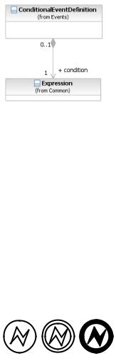
Figure 10.78 – ConditionalEventDefinition Class Diagram
The ConditionalEventDefinition element inherits the attributes and model associations of BaseElement (see Table 8.5) through its relationship to the EventDefinition element (see page 259). Table 10.95 presents the additional model associations of the ConditionalEventDefinition element.
Table 10.95 – ConditionalEventDefinition model associations
Attribute Name |
Description/Usage |
|
|
condition: Expression |
The Expression might be underspecified and provided in the form of natural |
|
|
|
language. For executable Processes (isExecutable = true), if the trigger is |
|
Conditional, then a FormalExpression MUST be entered. |
Error Event
Figure 10.79 shows the variations of Conditional Events.
Figure 10.79 – Error Events
Figure 10.80 displays the class diagram for the ErrorEventDefinition.
264 |
Business Process Model and Notation (BPMN), v2.0.2 |
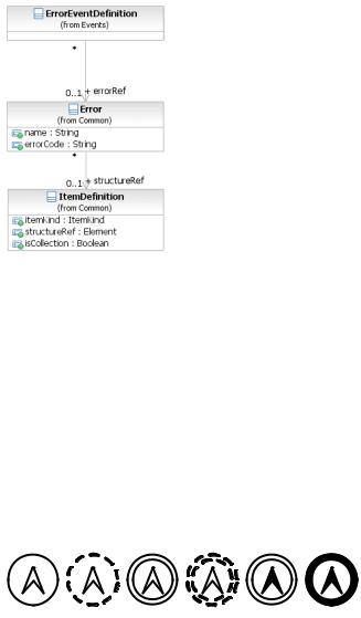
Figure 10.80 – ErrorEventDefinition Class Diagram
The ErrorEventDefinition element inherits the attributes and model associations of BaseElement (see Table 8.5) through its relationship to the EventDefinition element (see page 259). Table 10.96 presents the additional attributes and model associations of the ErrorEventDefinition element.
Table 10.96 – ErrorEventDefinition attributes and model associations
Attribute Name |
Description/Usage |
|
|
error: Error [0..1] |
If the trigger is an Error, then an Error payload MAY be provided. |
|
Escalation Event Definition
Figure 10.81 shows the variations of Escalation Events.
Figure 10.81 – Escalation Events
Figure 10.82 displays the class diagram for the EscalationEventDefinition.
Business Process Model and Notation (BPMN), v2.0.2 |
265 |
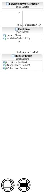
Figure 10.82 – EscalationEventDefinition Class Diagram
The EscalationEventDefinition element inherits the attributes and model associations of BaseElement (see Table 8.5) through its relationship to the EventDefinition element (see page 259). Table 10.97 presents the additional attributes and model associations of the EscalationEventDefinition element.
Table 10.97 – EscalationEventDefinition attributes and model associations
Attribute Name |
Description/Usage |
|
|
|
|
escalationRef: Escalation |
If the trigger is an Escalation, then an Escalation payload MAY be |
|
[0..1] |
||
provided. |
||
|
||
|
|
Link Event Definition
A Link Event is a mechanism for connecting two sections of a Process. Link Events can be used to create looping situations or to avoid long Sequence Flow lines. The use of Link Events is limited to a single Process level (i.e., they cannot link a parent Process with a Sub-Process).
Figure 10.83 shows the variations of Link Events.
Figure 10.83 – Link Events
Paired Link Events can also be used as “Off-Page Connectors” for printing a Process across multiple pages. They can also be used as generic “Go To” objects within the Process level. There can be multiple source Link Events, but there can only be one target Link Event. When used to “catch” from the source Link, the Event marker will be unfilled (see Figure 10.84: upper right). When used to “throw” to the target Link, the Event marker will be filled (see Figure 10.84: upper: lower Left).
266 |
Business Process Model and Notation (BPMN), v2.0.2 |
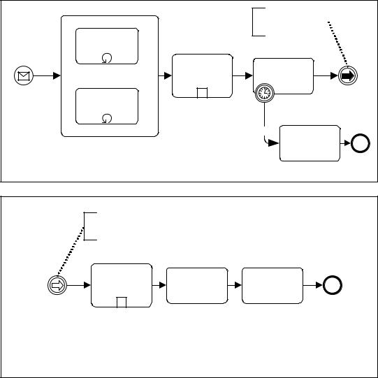
Since Process models often extend beyond the length of one printed page, there is often a concern about showing how Sequence Flow connections extend across the page breaks. One solution that is often employed is the use of Off-Page connectors to show where one page leaves off and the other begins. BPMN provides Intermediate Events of type Link for use as Off-Page connectors (see Figure 10.84 --Note that the figure shows two different printed pages, not two Pools in one diagram). A pair of Link Events is used. One of the pair is shown at the end of one page. This Event is named and has an incoming Sequence Flow and no outgoing Sequence Flows. The second Link Event is at the beginning of the next page, shares the same name, and has an outgoing Sequence Flow and no incoming Sequence Flow.
Request Flights within Parameters
Travel
Order Request Rooms
within Parameters
Source
Link Event
Prepare and |
Receive |
|
Send Candidate |
||
Confirmation |
||
Itineraries |
||
|
+ |
A |
2 Days
Send Cancellation
Notice
Page 1
Target
Link Event
Book
Reservations
A |
+ |
Charge |
Send Confirmation |
|
Buyer |
||
|
Page 2
Figure 10.84 – Link Events Used as Off-Page Connector
Another way that Link Events can be used is as “Go To” objects. Functionally, they would work the same as for OffPage Connectors (described above), except that they could be used anywhere in the diagram on the same page or across multiple pages. The general idea is that they provide a mechanism for reducing the length of Sequence Flow lines.
Some modelers can consider long lines as being hard to follow or trace. Go To Objects can be used to avoid very long
Business Process Model and Notation (BPMN), v2.0.2 |
267 |
Sequence Flows (see Figure 10.85 and Figure 10.86). Both diagrams will behave equivalently. For Figure 10.86, if the “Order Rejected” path is taken from the Decision, then the token traversing the Sequence Flow would reach the source Link Event and then “jump” to the target Link Event and continue down the Sequence Flow. The Process would continue as if the Sequence Flow had directly connected the two objects.
|
Order rejected |
|
|
Requested |
Ship Order |
|
|
Order |
|
|
|
|
|
|
|
Receive |
Order |
|
|
Order |
accepted Fill Order |
|
Close Order |
Request |
|
|
|
|
Send |
Make |
Accept |
|
Invoice |
Payment |
Payment |
|
Invoice |
|
|
Figure 10.85 – A Process with a long Sequence Flow
|
To Close |
|
|
To Close |
Requested |
Order rejected |
Ship Order |
|
|
Order |
|
|
||
|
|
|
|
|
Receive |
Order |
|
|
|
Order |
accepted |
Fill Order |
|
Close Order |
Request |
|
|
|
|
|
|
Send |
Make |
Accept |
|
|
Invoice |
Payment |
Payment |
Invoice
Figure 10.86 – A Process with Link Intermediate Events used as Go To Objects
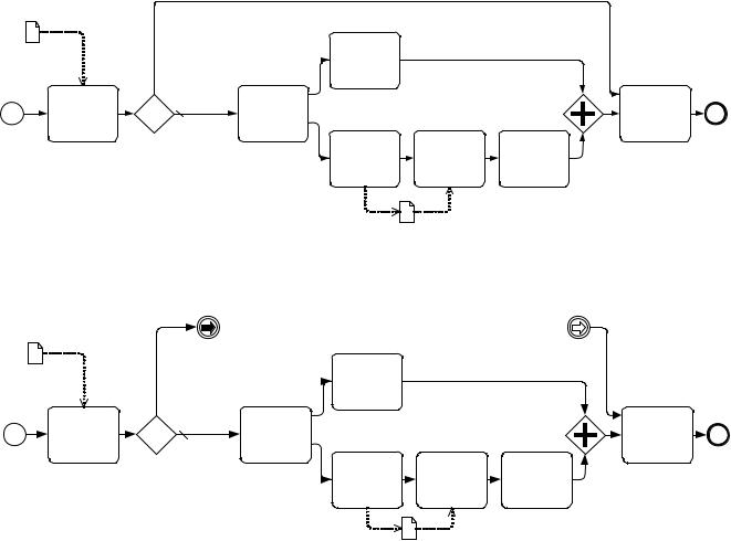
Some methodologies prefer that all Sequence Flows only move in one direction; that is, forward in time. These methodologies do not allow Sequence Flows to connect directly to upstream objects. Some consistency in modeling can be gained by such a methodology, but situations that require looping become a challenge. Link Events can be used to make upstream connections and create loops without violating the Sequence Flow direction restriction (see Figure 10.87).
268 |
Business Process Model and Notation (BPMN), v2.0.2 |