

- •1 Scope
- •1.1 General
- •2 Conformance
- •2.1 General
- •2.2 Process Modeling Conformance
- •2.2.1 BPMN Process Types
- •2.2.2 BPMN Process Elements
- •Descriptive Conformance Sub-Class
- •Analytic Conformance Sub-Class
- •Common Executable Conformance Sub-Class
- •2.2.3 Visual Appearance
- •2.2.4 Structural Conformance
- •2.2.5 Process Semantics
- •2.2.6 Attributes and Model Associations
- •2.2.7 Extended and Optional Elements
- •2.2.8 Visual Interchange
- •2.3 Process Execution Conformance
- •2.3.1 Execution Semantics
- •2.3.2 Import of Process Diagrams
- •2.4 BPEL Process Execution Conformance
- •2.5 Choreography Modeling Conformance
- •2.5.1 BPMN Choreography Types
- •2.5.2 BPMN Choreography Elements
- •2.5.3 Visual Appearance
- •2.5.4 Choreography Semantics
- •2.5.5 Visual Interchange
- •2.6 Summary of BPMN Conformance Types
- •3 Normative References
- •3.1 General
- •3.2 Normative
- •3.3 Non-Normative
- •Activity Service
- •BPEL4People
- •Business Process Definition Metamodel
- •Business Process Modeling
- •Business Transaction Protocol
- •Dublin Core Meta Data
- •ebXML BPSS
- •Open Nested Transactions
- •SOAP 1.2
- •UDDI
- •WfMC Glossary
- •Web Services Transaction
- •Workflow Patterns
- •WSBPEL
- •WS-Coordination
- •WSDL
- •WS-HumanTask
- •XML 1.0 (Second Edition)
- •XML-Namespaces
- •XML-Schema
- •XPath
- •XPDL
- •4 Terms and Definitions
- •5 Symbols
- •6 Additional Information
- •6.1 Conventions
- •6.1.1 Typographical and Linguistic Conventions and Style
- •6.1.2 Abbreviations
- •6.2 Structure of this Document
- •6.3 Acknowledgments
- •Submitting Organizations
- •Supporting Organizations
- •Special Acknowledgments
- •7 Overview
- •7.1 General
- •7.2 BPMN Scope
- •7.2.1 Uses of BPMN
- •Private (Internal) Business Processes
- •Public Processes
- •Collaborations
- •Choreographies
- •Conversations
- •Diagram Point of View
- •Understanding the Behavior of Diagrams
- •7.3 BPMN Elements
- •7.3.1 Basic BPMN Modeling Elements
- •7.3.2 Extended BPMN Modeling Elements
- •7.4 BPMN Diagram Types
- •7.5 Use of Text, Color, Size, and Lines in a Diagram
- •7.6 Flow Object Connection Rules
- •7.6.1 Sequence Flow Connections Rules
- •7.6.2 Message Flow Connection Rules
- •7.7 BPMN Extensibility
- •7.8 BPMN Example
- •8 BPMN Core Structure
- •8.1 General
- •8.2 Infrastructure
- •8.2.1 Definitions
- •8.2.2 Import
- •8.2.3 Infrastructure Package XML Schemas
- •8.3 Foundation
- •8.3.1 Base Element
- •8.3.2 Documentation
- •8.3.3 Extensibility
- •Extension
- •ExtensionDefinition
- •ExtensionAttributeDefinition
- •ExtensionAttributeValue
- •Extensibility XML Schemas
- •XML Example
- •8.3.4 External Relationships
- •8.3.5 Root Element
- •8.3.6 Foundation Package XML Schemas
- •8.4 Common Elements
- •8.4.1 Artifacts
- •Common Artifact Definitions
- •Artifact Sequence Flow Connections
- •Artifact Message Flow Connections
- •Association
- •Group
- •Category
- •Text Annotation
- •XML Schema for Artifacts
- •8.4.2 Correlation
- •CorrelationKey
- •Key-based Correlation
- •Context-based Correlation
- •XML Schema for Correlation
- •8.4.3 Error
- •8.4.4 Escalation
- •8.4.5 Events
- •8.4.6 Expressions
- •Expression
- •Formal Expression
- •8.4.7 Flow Element
- •8.4.8 Flow Elements Container
- •8.4.9 Gateways
- •8.4.10 Item Definition
- •8.4.11 Message
- •8.4.12 Resources
- •8.4.13 Sequence Flow
- •Flow Node
- •8.4.14 Common Package XML Schemas
- •8.5 Services
- •8.5.1 Interface
- •8.5.2 EndPoint
- •8.5.3 Operation
- •8.5.4 Service Package XML Schemas
- •9 Collaboration
- •9.1 General
- •9.2 Basic Collaboration Concepts
- •9.2.1 Use of BPMN Common Elements
- •9.3 Pool and Participant
- •9.3.1 Participants
- •PartnerEntity
- •PartnerRole
- •Participant Multiplicity
- •ParticipantAssociation
- •9.3.2 Lanes
- •9.4 Message Flow
- •9.4.1 Interaction Node
- •9.4.2 Message Flow Associations
- •9.5 Conversations
- •9.5.1 Conversation Node
- •9.5.2 Conversation
- •9.5.3 Sub-Conversation
- •9.5.4 Call Conversation
- •9.5.5 Global Conversation
- •9.5.6 Conversation Link
- •9.5.7 Conversation Association
- •9.5.8 Correlations
- •9.6 Process within Collaboration
- •9.7 Choreography within Collaboration
- •9.8 Collaboration Package XML Schemas
- •10 Process
- •10.1 General
- •10.2 Basic Process Concepts
- •10.2.1 Types of BPMN Processes
- •10.2.2 Use of BPMN Common Elements
- •10.3 Activities
- •Sequence Flow Connections
- •Message Flow Connections
- •10.3.1 Resource Assignment
- •Resource Role
- •Expression Assignment
- •Parameterized Resource Assignment
- •10.3.2 Performer
- •10.3.3 Tasks
- •Service Task
- •Send Task
- •Receive Task
- •User Task
- •Manual Task
- •Business Rule
- •Script Task
- •10.3.4 Human Interactions
- •Notation
- •Manual Task
- •User Task
- •Rendering of User Tasks
- •Human Performers
- •Potential Owners
- •XML Schema for Human Interactions
- •Examples
- •10.3.5 Sub-Processes
- •Embedded Sub-Process (Sub-Process)
- •Reusable Sub-Process (Call Activity)
- •Event Sub-Process
- •Transaction
- •Ad-Hoc Sub-Process
- •10.3.6 Call Activity
- •Callable Element
- •10.3.7 Global Task
- •Types of Global Task
- •10.3.8 Loop Characteristics
- •Standard Loop Characteristics
- •Multi-Instance Characteristics
- •Complex Behavior Definition
- •10.3.9 XML Schema for Activities
- •10.4 Items and Data
- •10.4.1 Data Modeling
- •Item-Aware Elements
- •Data Objects
- •DataObject
- •States
- •Data Objects representing a Collection of Data
- •Visual representations of Data Objects
- •Lifecycle and Accessibility
- •Data Stores
- •Properties
- •Lifecycle and Accessibility
- •Data Inputs and Outputs
- •Data Input
- •States
- •Data Output
- •States
- •Service Task Mapping
- •Send Task Mapping
- •Receive Task Mapping
- •User Task Mapping
- •Call Activity Mapping
- •Script Task Mapping
- •Events
- •InputSet
- •OutputSet
- •Data Associations
- •DataAssociation
- •Assignment
- •DataInputAssociation
- •DataOutputAssociation
- •Data Objects associated with a Sequence Flow
- •10.4.2 Execution Semantics for Data
- •Execution Semantics for DataAssociation
- •10.4.3 Usage of Data in XPath Expressions
- •Access to BPMN Data Objects
- •Access to BPMN Data Input and Data Output
- •Access to BPMN Properties
- •For BPMN Instance Attributes
- •10.4.4 XML Schema for Data
- •10.5 Events
- •10.5.1 Concepts
- •Data Modeling and Events
- •Common Event attributes
- •Common Catch Event attributes
- •Common Throw Event Attributes
- •Implicit Throw Event
- •10.5.2 Start Event
- •Start Event Triggers
- •Start Events for Top-level Processes
- •Start Events for Sub-Processes
- •Start Events for Event Sub-Processes
- •Attributes for Start Events
- •Sequence Flow Connections
- •Message Flow Connections
- •10.5.3 End Event
- •End Event Results
- •Sequence Flow Connections
- •Message Flow Connections
- •10.5.4 Intermediate Event
- •Intermediate Event Triggers
- •Intermediate Events in Normal Flow
- •Intermediate Events Attached to an Activity Boundary
- •Attributes for Boundary Events
- •Activity Boundary Connections
- •Sequence Flow Connections
- •Message Flow Connections
- •10.5.5 Event Definitions
- •Event Definition Metamodel
- •Cancel Event
- •Compensation Event
- •Conditional Event
- •Error Event
- •Escalation Event Definition
- •Link Event Definition
- •Message Event Definition
- •Multiple Event
- •None Event
- •Parallel Multiple Event
- •Signal Event
- •Terminate Event
- •Timer Event
- •10.5.6 Handling Events
- •Handling Start Events
- •Handling Events within normal Sequence Flow (Intermediate Events)
- •Handling Events attached to an Activity (Intermediate boundary Events and Event Sub-Processes)
- •Interrupting Event Handlers (Error, Escalation, Message, Signal, Timer, Conditional, Multiple, and Parallel Multiple)
- •Non-interrupting Event Handlers (Escalation, Message, Signal, Timer, Conditional, Multiple, and Parallel Multiple)
- •Handling End Events
- •10.5.7 Scopes
- •10.5.8 Events Package XML Schemas
- •10.6 Gateways
- •10.6.1 Sequence Flow Considerations
- •10.6.2 Exclusive Gateway
- •10.6.3 Inclusive Gateway
- •10.6.4 Parallel Gateway
- •10.6.5 Complex Gateway
- •10.6.6 Event-Based Gateway
- •10.6.7 Gateway Package XML Schemas
- •10.7 Compensation
- •10.7.1 Compensation Handler
- •10.7.2 Compensation Triggering
- •10.7.3 Relationship between Error Handling and Compensation
- •10.8 Lanes
- •10.9 Process Instances, Unmodeled Activities, and Public Processes
- •10.10 Auditing
- •10.11 Monitoring
- •10.12 Process Package XML Schemas
- •11 Choreography
- •11.1 General
- •11.2 Basic Choreography Concepts
- •11.3 Data
- •11.4 Use of BPMN Common Elements
- •11.4.1 Sequence Flow
- •11.4.2 Artifacts
- •11.5 Choreography Activities
- •11.5.1 Choreography Task
- •11.5.2 Sub-Choreography
- •The Parent Sub-Choreography (Expanded)
- •11.5.3 Call Choreography
- •11.5.4 Global Choreography Task
- •11.5.5 Looping Activities
- •11.5.6 The Sequencing of Activities
- •11.6 Events
- •11.6.1 Start Events
- •11.6.2 Intermediate Events
- •11.6.3 End Events
- •11.7 Gateways
- •11.7.1 Exclusive Gateway
- •11.7.2 Event-Based Gateway
- •11.7.3 Inclusive Gateway
- •11.7.4 Parallel Gateway
- •11.7.5 Complex Gateway
- •11.7.6 Chaining Gateways
- •11.8 Choreography within Collaboration
- •11.8.1 Participants
- •11.8.2 Swimlanes
- •Choreography Task in Combined View
- •Sub-Choreography in Combined View
- •11.9 XML Schema for Choreography
- •12 BPMN Notation and Diagrams
- •12.1 BPMN Diagram Interchange (BPMN DI)
- •12.1.1 Scope
- •12.1.2 Diagram Definition and Interchange
- •12.1.3 How to Read this Clause
- •12.2 BPMN Diagram Interchange (DI) Meta-model
- •12.2.1 Overview
- •12.2.2 Abstract Syntax
- •12.2.3 Classifier Descriptions
- •12.2.4 Complete BPMN DI XML Schema
- •12.3 Notational Depiction Library and Abstract Element Resolutions
- •12.3.1 Labels
- •12.3.2 BPMNShape
- •Markers for Activities
- •Tasks [BPMNShape]
- •Collapsed Sub-Processes [BPMNShape]
- •Expanded Sub-Processes [BPMNShape]
- •Collapsed Ad Hoc Sub-Processes [BPMNShape]
- •Expanded Ad Hoc Sub-Processes [BPMNShape]
- •Collapsed Transactions [BPMNShape]
- •Expanded Transactions [BPMNShape]
- •Collapsed Event Sub-Processes [BPMNShape]
- •Expanded Event Sub-Processes [BPMNShape]
- •Call Activities (Calling a Global Task) [BPMNShape]
- •Collapsed Call Activities (Calling a Process) [BPMNShape]
- •Expanded Call Activities (Calling a Process) [BPMNShape]
- •Data [BPMNShape]
- •Events [BPMNShape]
- •Gateways [BPMNShape]
- •Artifacts [BPMNShape]
- •Lanes [BPMNShape]
- •Pools [BPMNShape]
- •Choreography Tasks [BPMNShape]
- •Collapsed Sub-Choreographies [BPMNShape]
- •Expanded Sub-Choreographies [BPMNShape]
- •Call Choreographies (Calling a Global Choreography Task) [BPMNShape]
- •Collapsed Call Choreographies (Calling a Choreography) [BPMNShape]
- •Expanded Call Choreographies (Calling a Choreography) [BPMNShape]
- •Choreography Participant Bands [BPMNShape]
- •Conversations [BPMNShape]
- •12.3.3 BPMNEdge
- •Connecting Objects [BPMNEdge]
- •12.4 Example(s)
- •12.4.1 Depicting Content in a Sub-Process
- •Expanded Sub-Process
- •Expanded Sub-Process with Start and End Events on Border
- •Collapsed Sub-Process
- •12.4.2 Multiple Lanes and Nested Lanes
- •12.4.3 Vertical Collaboration
- •12.4.4 Conversation
- •12.4.5 Choreography
- •13 BPMN Execution Semantics
- •13.1 General
- •13.2 Process Instantiation and Termination
- •13.3 Activities
- •13.3.1 Sequence Flow Considerations
- •13.3.2 Activity
- •13.3.3 Task
- •13.3.4 Sub-Process/Call Activity
- •13.3.5 Ad-Hoc Sub-Process
- •Operational semantics
- •13.3.6 Loop Activity
- •13.3.7 Multiple Instances Activity
- •13.4 Gateways
- •13.4.1 Parallel Gateway (Fork and Join)
- •13.4.2 Exclusive Gateway (Exclusive Decision (data-based) and Exclusive Merge)
- •13.4.3 Inclusive Gateway (Inclusive Decision and Inclusive Merge)
- •13.4.4 Event-based Gateway (Exclusive Decision (event-based))
- •13.4.5 Complex Gateway (related to Complex Condition and Complex Merge)
- •13.5 Events
- •13.5.1 Start Events
- •13.5.2 Intermediate Events
- •13.5.3 Intermediate Boundary Events
- •13.5.4 Event Sub-Processes
- •Operational semantics
- •13.5.5 Compensation
- •Compensation Handler
- •Compensation Triggering
- •Relationship between Error Handling and Compensation
- •Operational Semantics
- •13.5.6 End Events
- •Process level end events
- •Sub-process level end events
- •14 Mapping BPMN Models to WS-BPEL
- •14.1 General
- •14.2 Basic BPMN-BPEL Mapping
- •14.2.1 Process
- •14.2.2 Activities
- •Common Activity Mappings
- •Task Mappings
- •Service Task
- •Receive Task
- •Send Task
- •Abstract Task
- •Service Package
- •Message
- •Interface and Operation
- •Conversations and Correlation
- •Sub-Process Mappings
- •Mapping of Event Sub-Processes
- •Activity Loop Mapping
- •Standard Loops
- •Dealing with LoopMaximum
- •Multi-Instance Activities
- •14.2.3 Events
- •Start Event Mappings
- •Message Start Events
- •Error Start Events
- •Compensation Start Events
- •Intermediate Event Mappings (Non-boundary)
- •Message Intermediate Events (Non-boundary)
- •Timer Intermediate Events (Non-boundary)
- •Compensation Intermediate Events (Non-boundary)
- •End Event Mappings
- •None End Events
- •Message End Events
- •Error End Events
- •Compensation End Events
- •Terminate End Events
- •Boundary Intermediate Events
- •Message Boundary Events
- •Error Boundary Events
- •Compensation Boundary Events
- •Multiple Boundary Events, and Boundary Events with Loops
- •14.2.4 Gateways and Sequence Flows
- •Exclusive (Data-based) Decision Pattern
- •Exclusive (Event-based) Decision Pattern
- •Inclusive Decision Pattern
- •Parallel Pattern
- •Sequence Pattern
- •Structured Loop Patterns
- •Handling Loops in Sequence Flows
- •14.2.5 Handling Data
- •Data Objects
- •Properties
- •Input and Output Sets
- •Data Associations
- •Expressions
- •Assignments
- •14.3 Extended BPMN-BPEL Mapping
- •14.3.1 End Events
- •14.3.2 Loop/Switch Combinations From a Gateway
- •14.3.3 Interleaved Loops
- •14.3.4 Infinite Loops
- •14.3.5 BPMN Elements that Span Multiple WSBPEL Sub-Elements
- •15 Exchange Formats
- •15.1 Interchanging Incomplete Models
- •15.2 Machine Readable Files
- •15.3.1 Document Structure
- •15.3.2 References within the BPMN XSD
- •15.5 XSLT Transformation between XSD and XMI
- •B.1 Scope
- •B.2 Architecture
- •B.3 Diagram Common
- •B.3.1 Overview
- •B.3.2 Abstract Syntax
- •B.3.3 Classifier Descriptions
- •B.4 Diagram Interchange
- •B.4.1 Overview
- •B.4.2 Abstract Syntax
- •B.4.3 Classifier Descriptions
Assignments
For a Service Task with assignments, the WS-BPEL mapping results in a sequence of an assign activity, an invoke activity and another assign activity. The first assign deals with creating the service request Message from the data inputs of the Task, the second assign deals with creating the data outputs of the Task from the service response Message.
14.3 Extended BPMN-BPEL Mapping
Additional sound BPMN Process models whose block hierarchy contains blocks that have not been addressed in the previous sub clause can be mapped to WS-BPEL. For such BPMN Process models, in many cases there is no preferred single mapping of a particular block, but rather, multiple WS-BPEL patterns are possible to map that block to. Also, additional BPMN constructs can be mapped by using capabilities not available at the time of producing this specification, such as the upcoming OASIS BPEL4People standard to map BPMN User Tasks, or other WS-BPEL extensions.
Rather than describing or even mandating the mapping of such BPMN blocks, this specification allows for a semantic mapping of a BPMN Process model to an executable WS-BPEL process: The observable behavior of the target WSBPEL process MUST match the operational semantics of the mapped BPMN Process. Also, the mappings described in sub clause 15.1 SHOULD be used where applicable.
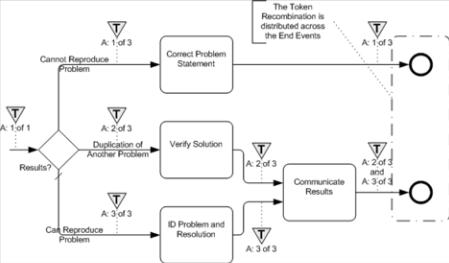
14.3.1 End Events
End Events can be combined with other BPMN objects to complete the merging or joining of the paths of a WSBPEL structured element (see Figure 7.3).
Figure 14.2 – An example of distributed token recombination
14.3.2 Loop/Switch Combinations From a Gateway
This type of loop is created by a Gateway that has three or more outgoing Sequence Flows. One Sequence Flow loops back upstream while the others continue downstream (see Figure 14.3). Note that there might be intervening
Activities prior to when the Sequence Flow loops back upstream.
Business Process Model and Notation (BPMN), v2.0.2 |
469 |
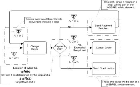
•This maps to both a WSBPEL while and a switch. Both activities will be placed within a sequence, with the while preceding the switch.
•For the while:
•The Condition for the Sequence Flow that loops back upstream will map to the condition of the while.
•All the Activities that span the distance between where the loop starts and where it ends, will be mapped and placed within the Activity for the while, usually within a sequence.
•For the switch:
•For each additional outgoing Sequence Flows there will be a case for the switch.
Figure 14.3 – An example of a loop from a decision with more than two alternative paths
14.3.3 Interleaved Loops
This is a situation where there are at least two loops involved and they are not nested (see Figure 14.4). Multiple looping situations can map, as described above, if they are in a sequence or are fully nested (e.g., one while inside another while). However, if the loops overlap in a non-nested fashion, as shown in the figure, then the structured element while cannot be used to handle the situation. Also, since a flow is acyclic, it cannot handle the behavior either.
470 |
Business Process Model and Notation (BPMN), v2.0.2 |
Figure 14.4 – An example of interleaved loops
To handle this type of behavior, parts of the WSBPEL process will have to be separated into one or more derived processes that are spawned from the main process and will also spawn or call each other (note that the examples below are using a spawning technique). Through this mechanism, the linear and structured elements of WSBPEL can provide the same behavior that is shown through a set of cycles in a single BPMN diagram. To do this:
•The looping section of the Process, where the loops first merge back (upstream) into the flow until all the paths have merged back to Normal Flow, SHALL be separated from the main WSBPEL process into a set of derived processes that will spawn each other until all the looping conditions are satisfied.
•The section of the process that is removed will be replaced by a (one-way) invoke to spawn the derived process, followed by a receive to accept the message that the looping sections have completed and the main process can continue (see Figure 14.5).
•The name of the invoke will be in the form of:
•“Spawn_[(loop target)activity.Name]_Derived_Process”
•The name of the receive will be in the form of:
•[(loop target)activity.Name]_Derived_Process_Completed”
Business Process Model and Notation (BPMN), v2.0.2 |
471 |
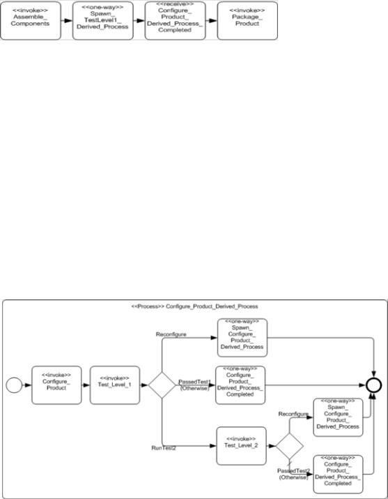
Figure 14.5 – An example of the WSBPEL pattern for substituting for the derived Process
For each location in the Process where a Sequence Flow connects upstream, there will be a separate derived WSBPEL process.
•The name of the derived process will be in the form of:
•“[(loop target)activity.Name]_Derived_Process”
•All Gateways in this sub clause will be mapped to switch elements, instead of while elements (see Figure below).
•Each time there is a Sequence Flow that loops back upstream, the Activity for the switch case will be a (oneway) invoke that will spawn the appropriate derived process, even if the invoke spawns the same process again.
•The name of the invoke will be the same as the one described above.
•At the end of the derived process a (one-way) invoke will be used to signal the main process that all the derived activities have completed and the main process can continue.
•The name of the invoke will be in the form of:
•“[(loop target)activity.Name]_Derived_Process_Completed”
Figure 14.6 – An example of a WSBPEL pattern for the derived Process
472 |
Business Process Model and Notation (BPMN), v2.0.2 |