

- •1 Scope
- •1.1 General
- •2 Conformance
- •2.1 General
- •2.2 Process Modeling Conformance
- •2.2.1 BPMN Process Types
- •2.2.2 BPMN Process Elements
- •Descriptive Conformance Sub-Class
- •Analytic Conformance Sub-Class
- •Common Executable Conformance Sub-Class
- •2.2.3 Visual Appearance
- •2.2.4 Structural Conformance
- •2.2.5 Process Semantics
- •2.2.6 Attributes and Model Associations
- •2.2.7 Extended and Optional Elements
- •2.2.8 Visual Interchange
- •2.3 Process Execution Conformance
- •2.3.1 Execution Semantics
- •2.3.2 Import of Process Diagrams
- •2.4 BPEL Process Execution Conformance
- •2.5 Choreography Modeling Conformance
- •2.5.1 BPMN Choreography Types
- •2.5.2 BPMN Choreography Elements
- •2.5.3 Visual Appearance
- •2.5.4 Choreography Semantics
- •2.5.5 Visual Interchange
- •2.6 Summary of BPMN Conformance Types
- •3 Normative References
- •3.1 General
- •3.2 Normative
- •3.3 Non-Normative
- •Activity Service
- •BPEL4People
- •Business Process Definition Metamodel
- •Business Process Modeling
- •Business Transaction Protocol
- •Dublin Core Meta Data
- •ebXML BPSS
- •Open Nested Transactions
- •SOAP 1.2
- •UDDI
- •WfMC Glossary
- •Web Services Transaction
- •Workflow Patterns
- •WSBPEL
- •WS-Coordination
- •WSDL
- •WS-HumanTask
- •XML 1.0 (Second Edition)
- •XML-Namespaces
- •XML-Schema
- •XPath
- •XPDL
- •4 Terms and Definitions
- •5 Symbols
- •6 Additional Information
- •6.1 Conventions
- •6.1.1 Typographical and Linguistic Conventions and Style
- •6.1.2 Abbreviations
- •6.2 Structure of this Document
- •6.3 Acknowledgments
- •Submitting Organizations
- •Supporting Organizations
- •Special Acknowledgments
- •7 Overview
- •7.1 General
- •7.2 BPMN Scope
- •7.2.1 Uses of BPMN
- •Private (Internal) Business Processes
- •Public Processes
- •Collaborations
- •Choreographies
- •Conversations
- •Diagram Point of View
- •Understanding the Behavior of Diagrams
- •7.3 BPMN Elements
- •7.3.1 Basic BPMN Modeling Elements
- •7.3.2 Extended BPMN Modeling Elements
- •7.4 BPMN Diagram Types
- •7.5 Use of Text, Color, Size, and Lines in a Diagram
- •7.6 Flow Object Connection Rules
- •7.6.1 Sequence Flow Connections Rules
- •7.6.2 Message Flow Connection Rules
- •7.7 BPMN Extensibility
- •7.8 BPMN Example
- •8 BPMN Core Structure
- •8.1 General
- •8.2 Infrastructure
- •8.2.1 Definitions
- •8.2.2 Import
- •8.2.3 Infrastructure Package XML Schemas
- •8.3 Foundation
- •8.3.1 Base Element
- •8.3.2 Documentation
- •8.3.3 Extensibility
- •Extension
- •ExtensionDefinition
- •ExtensionAttributeDefinition
- •ExtensionAttributeValue
- •Extensibility XML Schemas
- •XML Example
- •8.3.4 External Relationships
- •8.3.5 Root Element
- •8.3.6 Foundation Package XML Schemas
- •8.4 Common Elements
- •8.4.1 Artifacts
- •Common Artifact Definitions
- •Artifact Sequence Flow Connections
- •Artifact Message Flow Connections
- •Association
- •Group
- •Category
- •Text Annotation
- •XML Schema for Artifacts
- •8.4.2 Correlation
- •CorrelationKey
- •Key-based Correlation
- •Context-based Correlation
- •XML Schema for Correlation
- •8.4.3 Error
- •8.4.4 Escalation
- •8.4.5 Events
- •8.4.6 Expressions
- •Expression
- •Formal Expression
- •8.4.7 Flow Element
- •8.4.8 Flow Elements Container
- •8.4.9 Gateways
- •8.4.10 Item Definition
- •8.4.11 Message
- •8.4.12 Resources
- •8.4.13 Sequence Flow
- •Flow Node
- •8.4.14 Common Package XML Schemas
- •8.5 Services
- •8.5.1 Interface
- •8.5.2 EndPoint
- •8.5.3 Operation
- •8.5.4 Service Package XML Schemas
- •9 Collaboration
- •9.1 General
- •9.2 Basic Collaboration Concepts
- •9.2.1 Use of BPMN Common Elements
- •9.3 Pool and Participant
- •9.3.1 Participants
- •PartnerEntity
- •PartnerRole
- •Participant Multiplicity
- •ParticipantAssociation
- •9.3.2 Lanes
- •9.4 Message Flow
- •9.4.1 Interaction Node
- •9.4.2 Message Flow Associations
- •9.5 Conversations
- •9.5.1 Conversation Node
- •9.5.2 Conversation
- •9.5.3 Sub-Conversation
- •9.5.4 Call Conversation
- •9.5.5 Global Conversation
- •9.5.6 Conversation Link
- •9.5.7 Conversation Association
- •9.5.8 Correlations
- •9.6 Process within Collaboration
- •9.7 Choreography within Collaboration
- •9.8 Collaboration Package XML Schemas
- •10 Process
- •10.1 General
- •10.2 Basic Process Concepts
- •10.2.1 Types of BPMN Processes
- •10.2.2 Use of BPMN Common Elements
- •10.3 Activities
- •Sequence Flow Connections
- •Message Flow Connections
- •10.3.1 Resource Assignment
- •Resource Role
- •Expression Assignment
- •Parameterized Resource Assignment
- •10.3.2 Performer
- •10.3.3 Tasks
- •Service Task
- •Send Task
- •Receive Task
- •User Task
- •Manual Task
- •Business Rule
- •Script Task
- •10.3.4 Human Interactions
- •Notation
- •Manual Task
- •User Task
- •Rendering of User Tasks
- •Human Performers
- •Potential Owners
- •XML Schema for Human Interactions
- •Examples
- •10.3.5 Sub-Processes
- •Embedded Sub-Process (Sub-Process)
- •Reusable Sub-Process (Call Activity)
- •Event Sub-Process
- •Transaction
- •Ad-Hoc Sub-Process
- •10.3.6 Call Activity
- •Callable Element
- •10.3.7 Global Task
- •Types of Global Task
- •10.3.8 Loop Characteristics
- •Standard Loop Characteristics
- •Multi-Instance Characteristics
- •Complex Behavior Definition
- •10.3.9 XML Schema for Activities
- •10.4 Items and Data
- •10.4.1 Data Modeling
- •Item-Aware Elements
- •Data Objects
- •DataObject
- •States
- •Data Objects representing a Collection of Data
- •Visual representations of Data Objects
- •Lifecycle and Accessibility
- •Data Stores
- •Properties
- •Lifecycle and Accessibility
- •Data Inputs and Outputs
- •Data Input
- •States
- •Data Output
- •States
- •Service Task Mapping
- •Send Task Mapping
- •Receive Task Mapping
- •User Task Mapping
- •Call Activity Mapping
- •Script Task Mapping
- •Events
- •InputSet
- •OutputSet
- •Data Associations
- •DataAssociation
- •Assignment
- •DataInputAssociation
- •DataOutputAssociation
- •Data Objects associated with a Sequence Flow
- •10.4.2 Execution Semantics for Data
- •Execution Semantics for DataAssociation
- •10.4.3 Usage of Data in XPath Expressions
- •Access to BPMN Data Objects
- •Access to BPMN Data Input and Data Output
- •Access to BPMN Properties
- •For BPMN Instance Attributes
- •10.4.4 XML Schema for Data
- •10.5 Events
- •10.5.1 Concepts
- •Data Modeling and Events
- •Common Event attributes
- •Common Catch Event attributes
- •Common Throw Event Attributes
- •Implicit Throw Event
- •10.5.2 Start Event
- •Start Event Triggers
- •Start Events for Top-level Processes
- •Start Events for Sub-Processes
- •Start Events for Event Sub-Processes
- •Attributes for Start Events
- •Sequence Flow Connections
- •Message Flow Connections
- •10.5.3 End Event
- •End Event Results
- •Sequence Flow Connections
- •Message Flow Connections
- •10.5.4 Intermediate Event
- •Intermediate Event Triggers
- •Intermediate Events in Normal Flow
- •Intermediate Events Attached to an Activity Boundary
- •Attributes for Boundary Events
- •Activity Boundary Connections
- •Sequence Flow Connections
- •Message Flow Connections
- •10.5.5 Event Definitions
- •Event Definition Metamodel
- •Cancel Event
- •Compensation Event
- •Conditional Event
- •Error Event
- •Escalation Event Definition
- •Link Event Definition
- •Message Event Definition
- •Multiple Event
- •None Event
- •Parallel Multiple Event
- •Signal Event
- •Terminate Event
- •Timer Event
- •10.5.6 Handling Events
- •Handling Start Events
- •Handling Events within normal Sequence Flow (Intermediate Events)
- •Handling Events attached to an Activity (Intermediate boundary Events and Event Sub-Processes)
- •Interrupting Event Handlers (Error, Escalation, Message, Signal, Timer, Conditional, Multiple, and Parallel Multiple)
- •Non-interrupting Event Handlers (Escalation, Message, Signal, Timer, Conditional, Multiple, and Parallel Multiple)
- •Handling End Events
- •10.5.7 Scopes
- •10.5.8 Events Package XML Schemas
- •10.6 Gateways
- •10.6.1 Sequence Flow Considerations
- •10.6.2 Exclusive Gateway
- •10.6.3 Inclusive Gateway
- •10.6.4 Parallel Gateway
- •10.6.5 Complex Gateway
- •10.6.6 Event-Based Gateway
- •10.6.7 Gateway Package XML Schemas
- •10.7 Compensation
- •10.7.1 Compensation Handler
- •10.7.2 Compensation Triggering
- •10.7.3 Relationship between Error Handling and Compensation
- •10.8 Lanes
- •10.9 Process Instances, Unmodeled Activities, and Public Processes
- •10.10 Auditing
- •10.11 Monitoring
- •10.12 Process Package XML Schemas
- •11 Choreography
- •11.1 General
- •11.2 Basic Choreography Concepts
- •11.3 Data
- •11.4 Use of BPMN Common Elements
- •11.4.1 Sequence Flow
- •11.4.2 Artifacts
- •11.5 Choreography Activities
- •11.5.1 Choreography Task
- •11.5.2 Sub-Choreography
- •The Parent Sub-Choreography (Expanded)
- •11.5.3 Call Choreography
- •11.5.4 Global Choreography Task
- •11.5.5 Looping Activities
- •11.5.6 The Sequencing of Activities
- •11.6 Events
- •11.6.1 Start Events
- •11.6.2 Intermediate Events
- •11.6.3 End Events
- •11.7 Gateways
- •11.7.1 Exclusive Gateway
- •11.7.2 Event-Based Gateway
- •11.7.3 Inclusive Gateway
- •11.7.4 Parallel Gateway
- •11.7.5 Complex Gateway
- •11.7.6 Chaining Gateways
- •11.8 Choreography within Collaboration
- •11.8.1 Participants
- •11.8.2 Swimlanes
- •Choreography Task in Combined View
- •Sub-Choreography in Combined View
- •11.9 XML Schema for Choreography
- •12 BPMN Notation and Diagrams
- •12.1 BPMN Diagram Interchange (BPMN DI)
- •12.1.1 Scope
- •12.1.2 Diagram Definition and Interchange
- •12.1.3 How to Read this Clause
- •12.2 BPMN Diagram Interchange (DI) Meta-model
- •12.2.1 Overview
- •12.2.2 Abstract Syntax
- •12.2.3 Classifier Descriptions
- •12.2.4 Complete BPMN DI XML Schema
- •12.3 Notational Depiction Library and Abstract Element Resolutions
- •12.3.1 Labels
- •12.3.2 BPMNShape
- •Markers for Activities
- •Tasks [BPMNShape]
- •Collapsed Sub-Processes [BPMNShape]
- •Expanded Sub-Processes [BPMNShape]
- •Collapsed Ad Hoc Sub-Processes [BPMNShape]
- •Expanded Ad Hoc Sub-Processes [BPMNShape]
- •Collapsed Transactions [BPMNShape]
- •Expanded Transactions [BPMNShape]
- •Collapsed Event Sub-Processes [BPMNShape]
- •Expanded Event Sub-Processes [BPMNShape]
- •Call Activities (Calling a Global Task) [BPMNShape]
- •Collapsed Call Activities (Calling a Process) [BPMNShape]
- •Expanded Call Activities (Calling a Process) [BPMNShape]
- •Data [BPMNShape]
- •Events [BPMNShape]
- •Gateways [BPMNShape]
- •Artifacts [BPMNShape]
- •Lanes [BPMNShape]
- •Pools [BPMNShape]
- •Choreography Tasks [BPMNShape]
- •Collapsed Sub-Choreographies [BPMNShape]
- •Expanded Sub-Choreographies [BPMNShape]
- •Call Choreographies (Calling a Global Choreography Task) [BPMNShape]
- •Collapsed Call Choreographies (Calling a Choreography) [BPMNShape]
- •Expanded Call Choreographies (Calling a Choreography) [BPMNShape]
- •Choreography Participant Bands [BPMNShape]
- •Conversations [BPMNShape]
- •12.3.3 BPMNEdge
- •Connecting Objects [BPMNEdge]
- •12.4 Example(s)
- •12.4.1 Depicting Content in a Sub-Process
- •Expanded Sub-Process
- •Expanded Sub-Process with Start and End Events on Border
- •Collapsed Sub-Process
- •12.4.2 Multiple Lanes and Nested Lanes
- •12.4.3 Vertical Collaboration
- •12.4.4 Conversation
- •12.4.5 Choreography
- •13 BPMN Execution Semantics
- •13.1 General
- •13.2 Process Instantiation and Termination
- •13.3 Activities
- •13.3.1 Sequence Flow Considerations
- •13.3.2 Activity
- •13.3.3 Task
- •13.3.4 Sub-Process/Call Activity
- •13.3.5 Ad-Hoc Sub-Process
- •Operational semantics
- •13.3.6 Loop Activity
- •13.3.7 Multiple Instances Activity
- •13.4 Gateways
- •13.4.1 Parallel Gateway (Fork and Join)
- •13.4.2 Exclusive Gateway (Exclusive Decision (data-based) and Exclusive Merge)
- •13.4.3 Inclusive Gateway (Inclusive Decision and Inclusive Merge)
- •13.4.4 Event-based Gateway (Exclusive Decision (event-based))
- •13.4.5 Complex Gateway (related to Complex Condition and Complex Merge)
- •13.5 Events
- •13.5.1 Start Events
- •13.5.2 Intermediate Events
- •13.5.3 Intermediate Boundary Events
- •13.5.4 Event Sub-Processes
- •Operational semantics
- •13.5.5 Compensation
- •Compensation Handler
- •Compensation Triggering
- •Relationship between Error Handling and Compensation
- •Operational Semantics
- •13.5.6 End Events
- •Process level end events
- •Sub-process level end events
- •14 Mapping BPMN Models to WS-BPEL
- •14.1 General
- •14.2 Basic BPMN-BPEL Mapping
- •14.2.1 Process
- •14.2.2 Activities
- •Common Activity Mappings
- •Task Mappings
- •Service Task
- •Receive Task
- •Send Task
- •Abstract Task
- •Service Package
- •Message
- •Interface and Operation
- •Conversations and Correlation
- •Sub-Process Mappings
- •Mapping of Event Sub-Processes
- •Activity Loop Mapping
- •Standard Loops
- •Dealing with LoopMaximum
- •Multi-Instance Activities
- •14.2.3 Events
- •Start Event Mappings
- •Message Start Events
- •Error Start Events
- •Compensation Start Events
- •Intermediate Event Mappings (Non-boundary)
- •Message Intermediate Events (Non-boundary)
- •Timer Intermediate Events (Non-boundary)
- •Compensation Intermediate Events (Non-boundary)
- •End Event Mappings
- •None End Events
- •Message End Events
- •Error End Events
- •Compensation End Events
- •Terminate End Events
- •Boundary Intermediate Events
- •Message Boundary Events
- •Error Boundary Events
- •Compensation Boundary Events
- •Multiple Boundary Events, and Boundary Events with Loops
- •14.2.4 Gateways and Sequence Flows
- •Exclusive (Data-based) Decision Pattern
- •Exclusive (Event-based) Decision Pattern
- •Inclusive Decision Pattern
- •Parallel Pattern
- •Sequence Pattern
- •Structured Loop Patterns
- •Handling Loops in Sequence Flows
- •14.2.5 Handling Data
- •Data Objects
- •Properties
- •Input and Output Sets
- •Data Associations
- •Expressions
- •Assignments
- •14.3 Extended BPMN-BPEL Mapping
- •14.3.1 End Events
- •14.3.2 Loop/Switch Combinations From a Gateway
- •14.3.3 Interleaved Loops
- •14.3.4 Infinite Loops
- •14.3.5 BPMN Elements that Span Multiple WSBPEL Sub-Elements
- •15 Exchange Formats
- •15.1 Interchanging Incomplete Models
- •15.2 Machine Readable Files
- •15.3.1 Document Structure
- •15.3.2 References within the BPMN XSD
- •15.5 XSLT Transformation between XSD and XMI
- •B.1 Scope
- •B.2 Architecture
- •B.3 Diagram Common
- •B.3.1 Overview
- •B.3.2 Abstract Syntax
- •B.3.3 Classifier Descriptions
- •B.4 Diagram Interchange
- •B.4.1 Overview
- •B.4.2 Abstract Syntax
- •B.4.3 Classifier Descriptions
B.4 Diagram Interchange
The Diagram Interchange (DI) package contains a model enabling interchange of graphical information that language users have control over, such as position of nodes and line routing points. Language specifications specialize elements of DI to define diagram interchange for a language.
B.4.1 Overview
The Diagram Interchange (DI) package contains a number of types used in the definition of diagram interchange models. The package imports the Diagram Common package (see “Diagram Common” on page 483), as shown in Figure B.5, that contains various relevant data types. The DI package contains mainly abstract types that are to be properly extended and refined by concrete types in domain-specific DI packages. In this sense, the DI package plays the role of a framework that is meant for extension rather than a component that is ready to be used out of the box. The benefit of this design is capture common assumptions in the DI package in order to facilitate the integration between various graphical domains that define their DI packages as extensions.
Diagrams are generally considered depictions of part or all of the elements in a domain-specific model. Therefore, one of the best practices adopted in the design of the DI package and that can be subsumed by the extending domain-specific DI packages is to minimize any redundancy with the depicted model when possible. For example, the text representing the name of a UML class is not defined as part of the UML class shape. This is primarily achieved by the fact that diagram elements reference their counterparts in the domain model as their context model elements instead of duplicating data from them. This design has the side effect of coupling the diagram models with their corresponding domain models, which is generally a common practice by tools. However, the DI package does not enforce this best practice and domainspecific DI packages can decide to have some level of duplication to decouple the models.
Another best practice adopted by the DI package is to avoid defining any data that is not changeable by the user but is rather derivable from the diagram’s model context, like graphical rendering details. For example, the option to render a UML actor as a stick man or a as rectangle can be defined in a DI model as a boolean property to allow a user to choose between them. However, the definition of the actual line segments making up such shapes need not be interchanged in a DI model as it can be defined in the tool itself.
Other decisions that are left to the individual domain-specific DI packages include: whether to allow 1-n vs. m-n relationships between the domain elements and their referencing diagram elements, the formatting properties (styles) that affect the aesthetics of diagrams rather than their semantics that are allowed to be interchanged, and the degree of pragmatic redundancy that is allowed in the DI models to balance their footprint with the ease of their import/export.
Business Process Model and Notation (BPMN), v2.0.2 |
487 |
B.4.2 Abstract Syntax
Figure B.5 – Dependencies of the DI package
Figure B.6 – Diagram Element
Figure B.7 – Node
488 |
Business Process Model and Notation (BPMN), v2.0.2 |
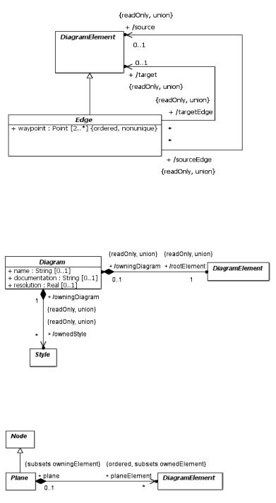
Figure B.8 – Edge
Figure B.9 – Diagram
Figure B.10 – Plane
Business Process Model and Notation (BPMN), v2.0.2 |
489 |
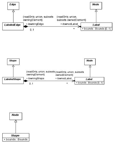
Figure B.11 – Labeled Edge
Figure B.12 – Labeled Shape
Figure B.13 – Shape
B.4.3 Classifier Descriptions
B.4.3.1 Diagram [Class]
Diagram is a container of a graph of diagram elements depicting all or part of a model.
Description
Diagram represents a depiction of all or part of a MOF model. A model can have one or more diagrams, each of which has a name and a description. A diagram contains the root of a graph of diagram elements that could reference various elements in a model. The root element is defined as a derived union, allowing domain-specific diagrams to specialize the root. All lengths specified by diagram elements are expressed in logical units of lengths. This unit of length would map to a unit of screen resolution (i.e., pixel) when rendering to the screen. To allow for predictable lengths when printing diagrams to paper, a diagram can also specify an intended printing resolution in Unit Per Inch (UPI). For example, a UPI of 300 means that a diagram element that is 300 unit wide would print as 1 inch wide on paper. A diagram can also own
490 |
Business Process Model and Notation (BPMN), v2.0.2 |
a collection of styles that are referenced by its diagram elements. Styles contain unique combination of formatting properties used by different elements across the diagram. This allows for a large number of diagram elements to reference a small number of unique styles, which would dramatically reduce a diagram’s footprint.
Abstract Syntax
• Figure B.9 Diagram
Attributes
• + name : String [0..1]
the name of the diagram.
• + documentation : String [0..1]
the documentation of the diagram.
• + resolution : Real [0..1]
the printing resolution of the diagram expressed in Unit Per Inch (UPI).
Associations
• ? + /rootElement : DiagramElement [1] {readOnly, union}
the root of containment for all diagram elements contained in the diagram.
• ? + /ownedStyle : Style [*] {readOnly, union}
the collection of styles owned by the diagram and referenced by its contained diagram elements.
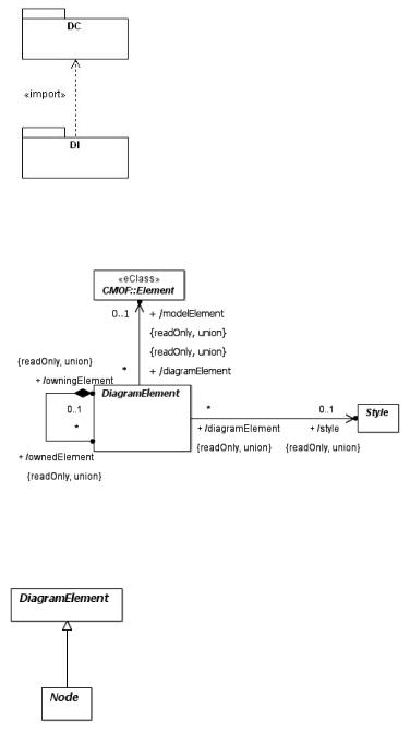
B.4.3.2 DiagramElement [Class]
DiagramElement is the abstract supertype of all elements that can be nested in a diagram. It has two subtypes: Node and Edge.
Description
DiagramElement specifies an element that can be owned by a diagram and rendered to graphics. It is an abstract class that is further specialized by classes Node and Edge. A diagram element can either depict (reference) another context model element from an abstract syntax model (like UML or BPMN) or be purely notational (i.e., for enhancing the diagram understanding). In the case of depiction, data from both the diagram element and the model element are used for rendering. For example, the text of the name label of a UML class shape comes from the class, while the color of the label comes from the diagram element. A diagram element can reference a maximum of one model element, which can be any MOF-based element. The model element reference is a derived union and can be specialized in a domain-specific DI metamodel to be of a more concrete type.
Diagram elements can also own other diagram elements in a graph-like hierarchy. The collection of owned diagram elements is defined as a derived union. Domain-specific DI metamodels can specialize this collections to define what other diagram elements can be nested in a given diagram element.
Diagram elements can be specialized in a domain-specific DI metamodel to have domain-specific properties. Some of those properties augment the semantics of diagram elements and are therefore defied on the diagram elements. Other properties are considered formatting properties that influence the visual rendering of diagram elements but do not contribute to their semantics. Examples of such formatting properties include font, fill and stroke properties. Such properties tend to have similar values for diagram elements across the diagram and therefore to reduce the footprint of
Business Process Model and Notation (BPMN), v2.0.2 |
491 |
diagrams, they are defined in Style elements that are owned by the diagram and referenced by individual diagram elements. For every unique combination of values for the style properties there would be a separate style element that is owned by the diagram. See “DiagramElement [Class]” on page 491 for more details.
There shall always be other properties that some tools wish to interchange that cannot be made normative. These can be interchanged using the extensibility mechanism that is native to the used interchange format (for example, an XSD schema following the XMI mapping would allow extraneous data to be placed on elements within <xmi:extension> tags, while a different XSD schema could allow this through xsd:any and xsd:anyAttribute elements placed in the definitions of extensible complex types).
Abstract Syntax
•Figure B.6 Diagram Element
•Figure B.7 Node
•Figure B.8 Edge
•Figure B.9 Diagram
•Figure B.10 Plane
Specializations
•Node
•Edge
Associations
• + /owningDiagram : Diagram [0..1] {readOnly, union}
a reference to the diagram that directly owns this diagram element. The reference is only set for the root element in a diagram.
• + /owningElement : DiagramElement [0..1] {readOnly, union}
a reference to the diagram element that directly owns this diagram element. The reference is set for all elements except the root element in a diagram.
• ? + /ownedElement : DiagramElement [*] {readOnly, union}
a collection of diagram elements that are owned by this diagram element.
• + /modelElement : Element [0..1] {readOnly, union}
a reference to a context model element, which can be any MOF-based element, for the diagram element.
• + /style : Style [0..1] {readOnly, union}
a reference to an optional style containing formatting properties for the diagram element.
B.4.3.3 Edge [Class]
Edge specifies a given edge in a graph of diagram elements. It represents a polyline connection between two graph elements: a source and a target.
492 |
Business Process Model and Notation (BPMN), v2.0.2 |
Description
Edge represents a given connection between two elements in a diagram, a source element and a target element. An edge often references a relationship element (like a UML generalization or a BPMN message flow) as a context model element. It can also be purely notational, i.e., does not reference any model element. When referencing a relationship model element, the edge’s source and target reference the relationship's source and target respectively as their model elements. If the edge’s source and target can be derived unambiguously from other info (like the edge’s model element or the edge’s class type), they are not explicitly set on the edge to avoid redundancy, otherwise they need to be set. The source and target are defined as derived unions to allow domain-specific DI metamodels to specialize them appropriately.
An edge is often depicted as a line with 2 or more points (i.e., one or more connected line segments) in the coordinate system, called waypoints. The first point typically intersects with the edge’s source, while the last point typically intersects with the edge’s target. Any points in between establish a route for the line to traverse in the diagram.
Abstract Syntax
•Figure B.8 Edge
•Figure B.11 Labeled Edge
Generalizations
• DiagramElement
Specializations
• LabeledEdge
Attributes
• + waypoint : Point [2..*] {ordered, nonunique}
a list of two or more points relative to the origin of the coordinate system (e.g., the origin of a containing plane) that specifies the connected line segments of the edge.
Associations
• + /source : DiagramElement [0..1] {readOnly, union}
the edge’s source diagram element, i.e., where the edge starts from. It is optional and needs to be set only if it cannot be unambiguously derived.
• + /target : DiagramElement [0..1] {readOnly, union}
the edge’s target diagram element, i.e., where the edge ends at. It is optional and needs to be set only if it cannot be unambiguously derived.
B.4.3.4 Label [Class]
Label represents a node that is owned by another main diagram element in a plane and that depicts some (usually textual) aspect of that element within its own separate bounds.
Description
Label represents an owned node of another diagram element, typically a LabeledShape or a LabeledEdge. A label typically depicts some (usually textual) aspect of its owning element that needs to be laid out separately using the label’s own bounds. The bounds are optional and if not specified, the label will be positioned in its default position.
Business Process Model and Notation (BPMN), v2.0.2 |
493 |
A label’s model element is typically not specified as it can be derived from its owning element. However, if the model element cannot be unambiguously derived, then a label could be given ts own separate model element to disambiguate it.
Abstract Syntax
•Figure B.11 (Labeled Edge)
•Figure B.12 Labeled Shape
Generalizations
• Node
Attributes
• + bounds : Bounds [1]
the bounds (x, y, width and height) of the label relative to the origin of a containing plane.
B.4.3.5 LabeledEdge [Class]
LabeledEdge represents an edge that owns a collection of labels.
Description
LabeledEdge is an edge that owns a collection of labels (see “LabeledEdge [Class]” on page 494) that depict some aspects of it. An example is a UML association that has a number of labels (e.g., a name label, two role name labels and two multiplicity labels) positioned beside it. The existence of a label in this collection specifies that it is visible. The separate optional bounds of the label indicate where it should be positioned and if not specified the label can be positioned in its default position.
Abstract Syntax
• Figure B.11 Labeled Edge
Generalizations
• Edge
Associations
• ? + /ownedLabel : Label [*] {readOnly, union, subsets ownedNode} the collection of labels owned by this edge.
B.4.3.6 LabeledShape [Class]
LabeledShape represents a shape that owns a collection of labels.
Description
LabeledShape is a shape that owns a collection of labels (see “LabeledShape [Class]” on page 494) that depict some aspects of it. An example is a UML port shape that is rendered as a filled box and has a name label positioned beside it. The existence of a label in this collection specifies that it is visible. The separate optional bounds of the label indicate where it should be positioned and if not specified the label can be positioned in its default position.
Abstract Syntax
• Figure B.12 Labeled Shape
494 |
Business Process Model and Notation (BPMN), v2.0.2 |
Generalizations
• Shape
Associations
• ? + /ownedLabel : Label [*] {readOnly, union, subsets ownedNode} the collection of labels owned by this shape.
B.4.3.7 Node [Class]
Node specifies a given node in a graph of diagram elements.
Description
Node represents a given node (or vertex) in a diagram, which is a graph of diagram elements. A node often references a non-relationship element (like a UML class or a BPMN activity) as a model element. It can also be purely notational, i.e., does not reference any model element.
The abstract node class does not have any particular layout characteristics. However, it may gets specialized in a domainspecific DI metamodel to define nodes that have certain layout characteristics. Examples include planes with infinite bounds, shapes with limited bounds, tree items and graph vertices...etc.
Abstract Syntax
•Figure B.7 Node
•Figure B.10 Plane
•Figure B.11 Labeled Edge
•Figure B.12 Labeled Shape
•Figure B.13 Shape
Generalizations
• DiagramElement
Specializations
•Label
•Shape
•Plane
B.4.3.8 Plane [Class]
Plane is a node with an infinite bounds in the x-y coordinate system that owns a collection of shapes and edges that are laid out relative to its origin point.
Description
Plane has an origin point (0, 0) and an infinite size along the x and y axes. The coordinate system of the plane increases along the x-axis from left to right and along the y-axis from top to bottom. All the nested shapes and edges are laid out relative to their plane’s origin.
Business Process Model and Notation (BPMN), v2.0.2 |
495 |
A plane is often chosen as a root element for a two dimensional diagram that depicts an inter-connected graph of shapes an edges. A plane may have its own reference to a model element, in which case the whole plane is considered a depiction of that element. Alternatively, a plane without a reference to a model element is simply a layout container for its shapes and edges.
The collection of plane elements (shapes and edges) in a plane is ordered with the order specifying the z-order of these plane elements relative to each other. The higher the z-order, the more to the front (on top) the plane element is.
Abstract Syntax
• Figure B.10 Plane
Generalizations
• Node
Associations
• ? + planeElement : DiagramElement [*] {subsets ownedNode}
the ordered collection of diagram elements owned by this plane with the order defining the z-order of the diagram element.
B.4.3.9 Shape [Class]
Shape represents a node that has bounds that is relevant to the origin of a containing plane.
Description
Shape represents a node that is directly or indirectly owned by a plane (See “Shape [Class]” on page 496.) and that is laid out according to a given bounds that is relevant to the origin of the plane. A shape does not have any particular graphical rendering, i.e., the rendering is domain-specific.
A shape can be purely notational (i.e., does not reference any model element), like a block arrow pointing to a UML class shape with some textual message or an overlay rectangle with some transparent fill enclosing a bunch of shapes on the diagram to make them stand out. However, a shape often represents a depiction of a non-relational element from a business model (like UML class or BPMN activity) and hence references such an element as its model element.
Abstract Syntax
•Figure B.13 Shape
•Figure B.12 Labeled Shape
Generalizations
• Node
Specializations
• LabeledShape
Attributes
• + bounds : Bounds [1]
the bounds (x, y, width and height) of the shape relative to the origin of a containing plane.
496 |
Business Process Model and Notation (BPMN), v2.0.2 |
B.4.3.10 Style [Class]
A style is a container for a collection of properties that affect the formatting of a set of diagram elements rather than their structure or semantics.
Description
A style represents a bag of properties that affect the appearance of a group of diagram elements. A style property (like font, fill, or stroke) is distinguishable from a property on a diagram element in that it is meant for the aesthetics of the element rather than being part of its intrinsic syntax.
A style tends to have only a few unique value combinations for its properties across the diagram. Such combinations are represented by different style instances owned by the diagram and referenced by the diagram elements. This allows for conserving the footprint of diagrams (over making style instances owned by diagram elements).
Style is defined as an abstract class without prescribing any style properties to leave it up to domain-specific DI metamodels to define concrete style classes that are applicable to their diagram element types.
Abstract Syntax
•Figure B.6 Diagram Element
•Figure B.9 Diagram
Business Process Model and Notation (BPMN), v2.0.2 |
497 |
498 |
Business Process Model and Notation (BPMN), v2.0.2 |
|
Annex C |
|
Glossary |
|
(informative) |
A |
|
Activity |
Work that a company or organization performs using business processes. An activity |
|
can be atomic or non-atomic (compound). The types of activities that are a part of a |
|
Process Model are: Process, Sub-Process, and Task. |
Abstract Process |
A Process that represents the interactions between a private business process and |
|
another process or participant. |
Artifact |
A graphical object that provides supporting information about the Process or |
|
elements within the Process. However, it does not directly affect the flow of the |
|
Process. |
Association |
A connecting object that is used to link information and Artifacts with Flow Objects. |
|
An association is represented as a dotted graphical line with an arrowhead to |
|
represent the direction of flow. |
Atomic Activity |
An activity not broken down to a finer level of Process Model detail. It is a leaf in |
|
the tree-structure hierarchy of Process activities. Graphically it will appear as a Task |
|
in BPMN. |
B |
|
Business Analyst |
A specialist who analyzes business needs and problems, consults with users and |
|
stakeholders to identify opportunities for improving business return through |
|
information technology, and defines, manages, and monitors the requirements into |
|
business processes. |
Business Process |
A defined set of business activities that represent the steps required to achieve a |
|
business objective. It includes the flow and use of information and resources. |
Business Process |
The services and tools that support process management (for example, process |
Management |
analysis, definition, processing, monitoring and administration), including support |
|
for human and application-level interaction. BPM tools can eliminate manual |
|
processes and automate the routing of requests between departments and |
|
applications. |
BPM System |
The technology that enables BPM. |
C |
|
Choreography |
An ordered sequence of B2B message exchanges between two or more Participants. |
|
In a Choreography there is no central controller, responsible entity, or observer of |
|
the Process. |
Collaboration |
Collaboration is the act of sending messages between any two Participants in a |
|
BPMN model. The two Participants represent two separate BPML processes. |
Collapsed Sub-Process |
A Sub-Process that hides its flow details. The Collapsed Sub-Process object uses a |
|
marker to distinguish it as a Sub-Process, rather than a Task. The marker is a small |
|
square with a plus sign (+) inside. |
|
|
Business Process Model and Notation (BPMN), v2.0.2 |
499 |
Compensation Flow |
Flow that defines the set of activities that are performed while the transaction is |
|
being rolled back to compensate for activities that were performed during the |
|
Normal Flow of the Process. A Compensation Flow can also be called from a |
|
Compensate End or Intermediate Event. |
Compound Activity |
An activity that has detail that is defined as a flow of other activities. It is a branch |
|
(or trunk) in the tree-structure hierarchy of Process activities. Graphically, it will |
|
appear as a Process or Sub-Process in BPMN. |
Controlled Flow |
Flow that proceeds from one Flow Object to another, via a Sequence Flow link, but |
|
is subject to either conditions or dependencies from other flow as defined by a |
|
Gateway. Typically, this is seen as a Sequence flow between two activities, with a |
|
conditional indicator (mini-diamond) or a Sequence Flow connected to a Gateway. |
D |
|
Decision |
A gateway within a business process where the Sequence Flow can take one of |
|
several alternative paths. Also known as "Or-Split." |
E |
|
End Event |
An Event that indicates where a path in the process will end. In terms of Sequence |
|
Flows, the End Event ends the flow of the Process, and thus, will not have any |
|
outgoing Sequence Flows. An End Event can have a specific Result that will appear |
|
as a marker within the center of the End Event shape. End Event Results are |
|
Message, Error, Compensation, Signal, Link, and Multiple. The End Event shares |
|
the same basic shape of the Start Event and Intermediate Event, a circle, but is drawn |
|
with a thick single line. |
Event Context |
An Event Context is the set of activities that can be interrupted by an exception |
|
(Intermediate Event). This can be one activity or a group of activities in an expanded |
|
Sub-Process. |
Exception |
An event that occurs during the performance of the Process that causes a diversion |
|
from the Normal Flow of the Process. Exceptions can be generated by Intermediate |
|
Events, such as time, error, or message. |
Exception Flow |
A Sequence Flow path that originates from an Intermediate Event attached to the |
|
boundary of an activity. The Process does not traverse this path unless the Activity |
|
is interrupted by the triggering of a boundary Intermediate Event (an Exception - see |
|
above). |
Expanded Sub-Process |
A Sub-Process that exposes its flow detail within the context of its Parent Process. |
|
An Expanded Sub-Process is displayed as a rounded rectangle that is enlarged to |
|
display the Flow Objects within. |
F |
|
Flow |
A directional connector between elements in a Process, Collaboration, or |
|
Choreography. A Sequence Flows represents the sequence of Flow Objects in a |
|
Process or Choreography. A Message Flow represents the transmission of a Message |
|
between Collaboration Participants.The term Flow is often used to represent the |
|
overall progression of how a Process or Process segment would be performed. |
Flow Object |
A graphical object that can be connected to or from a Sequence Flow. In a Process, |
|
Flow Objects are Events, Activities, and Gateways. In a Choreography, Flow |
|
Objects are Events, Choreography Activities, and Gateways. |
|
|
500 |
Business Process Model and Notation (BPMN), v2.0.2 |
Fork |
A point in the Process where one Sequence Flow path is split into two or more paths |
|
that are run in parallel within the Process, allowing multiple activities to run |
|
simultaneously rather than sequentially. BPMN uses multiple outgoing Sequence |
|
Flows from Activities or Events or a Parallel Gateway to perform a Fork. Also |
|
known as “AND-Split.” |
I |
|
Intermediate Event |
An event that occurs after a Process has been started. An Intermediate Event affects |
|
the flow of the process by showing where messages and delays are expected, |
|
distributing the Normal Flow through exception handling, or showing the extra flow |
|
required for compensation. However, an Intermediate Event does not start or |
|
directly terminate a process. An Intermediate Event is displayed as a circle, drawn |
|
with a thin double line. |
J |
|
Join |
A point in the Process where two or more parallel Sequence Flow paths are |
|
combined into one Sequence Flow path. BPMN uses a Parallel Gateway to perform |
|
a Join. Also known as “AND-Join.” |
L |
|
Lane |
A partition that is used to organize and categorize activities within a Pool. A Lane |
|
extends the entire length of the Pool either vertically or horizontally. Lanes are often |
|
used for such things as internal roles (e.g., Manager, Associate), systems (e.g., an |
|
enterprise application), or an internal department (e.g., shipping, finance). |
M |
|
Merge |
A point in the Process where two or more alternative Sequence Flow paths are |
|
combined into one Sequence Flow path. No synchronization is required because no |
|
parallel activity runs at the join point. BPMN uses multiple incoming Sequence |
|
Flows for an Activity or an Exclusive Gateway to perform a Merge. Also know as |
|
“OR-Join.” |
Message |
An Object that depicts the contents of a communication between two Participants. A |
|
message is transmitted through a Message Flow and has an identity that can be used |
|
for alternative branching of a Process through the Event-Based Exclusive Gateway. |
Message Flow |
A Connecting Object that shows the flow of messages between two Participants. A |
|
Message Flow is represented by a dashed lined. |
N |
|
Normal Flow |
A flow that originates from a Start Event and continues through activities on |
|
alternative and parallel paths until reaching an End Event. |
P |
|
Parent Process |
A Process that holds a Sub-Process within its boundaries. |
Participant |
A business entity (e.g., a company, company division, or a customer) or a business |
|
role (e.g., a buyer or a seller) that controls or is responsible for a business process. If |
|
Pools are used, then a Participant would be associated with one Pool. In a |
|
Collaboration, Participants are informally known as “Pools.” |
Pool |
A Pool represents a Participant in a Collaboration. Graphically, a Pool is a container |
|
for partitioning a Process from other Pools/Participants. A Pool is not required to |
|
contain a Process, i.e., it can be a “black box.” |
|
|
Business Process Model and Notation (BPMN), v2.0.2 |
501 |
Private Business Process |
A process that is internal to a specific organization and is the type of process that has |
|
been generally called a workflow or BPM process. |
Process |
A sequence or flow of Activities in an organization with the objective of carrying |
|
out work. In BPMN, a Process is depicted as a graph of Flow Elements, which are a |
|
set of Activities, Events, Gateways, and Sequence Flow that adhere to a finite |
|
execution semantics. |
R |
|
Result |
The consequence of reaching an End Event. Types of Results include Message, |
|
Error, Compensation, Signal, Link, and Multiple. |
S |
|
Sequence Flow |
A connecting object that shows the order in which activities are performed in a |
|
Process and is represented with a solid graphical line. Each Flow has only one source |
|
and only one target. A Sequence Flow can cross the boundaries between Lanes of a |
|
Pool but cannot cross the boundaries of a Pool. |
Start Event |
An Event that indicates where a particular Process starts. The Start Event starts the |
|
flow of the Process and does not have any incoming Sequence Flow, but can have a |
|
Trigger. The Start Event is displayed as a circle, drawn with a single thin line. |
Sub-Process |
A Process that is included within another Process. The Sub-Process can be in a |
|
collapsed view that hides its details. A Sub-Process can be in an expanded view that |
|
shows its details within the view of the Process that it is contained in. A Sub-Process |
|
shares the same shape as the Task, which is a rectangle that has rounded corners. |
Swimlane |
A Swimlane is a graphical container for partitioning a set of activities from other |
|
activities. BPMN has two different types of Swimlanes. See “Pool” and “Lane.” |
T |
|
Task |
An atomic activity that is included within a Process. A Task is used when the work |
|
in the Process is not broken down to a finer level of Process Model detail. Generally, |
|
an end-user, an application, or both will perform the Task. A Task object shares the |
|
same shape as the Sub-Process, which is a rectangle that has rounded corners. |
Token |
A theoretical concept that is used as an aid to define the behavior of a Process that |
|
is being performed. The behavior of Process elements can be defined by describing |
|
how they interact with a token as it “traverses” the structure of the Process. For |
|
example, a token will pass through an Exclusive Gateway, but continue down only |
|
one of the Gateway's outgoing Sequence Flow. |
Transaction |
A Sub-Process that represents a set of coordinated activities carried out by |
|
independent, loosely-coupled systems in accordance with a contractually defined |
|
business relationship. This coordination leads to an agreed, consistent, and verifiable |
|
outcome across all participants. |
Trigger |
A mechanism that detects an occurrence and can cause additional processing in |
|
response, such as the start of a business Process. Triggers are associated with Start |
|
Events and Intermediate Events and can be of the type: Message, Timer, |
|
Conditional, Signal, Link, and Multiple. |
U |
|
Uncontrolled Flow |
Flow that proceeds without dependencies or conditional expressions. Typically, an |
|
Uncontrolled Flow is a Sequence Flow between two Activities that do not have a |
|
conditional indicator (mini-diamond) or an intervening Gateway. |
|
|
502 |
Business Process Model and Notation (BPMN), v2.0.2 |