

Accessories
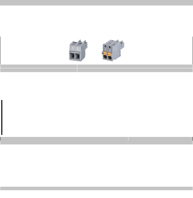
8.2 TB6102 2-pin power supply connector
This 1-row 2-pin terminal block is used to connect the power supply.
8.2.1 Order data
Model number |
Short description |
|
Terminal blocks |
0TB6102.2010-01 |
Accessory terminal block, 2-pin (3.81), screw clamp terminal block 1.5 mm² |
0TB6102.2110-01 |
Accessory terminal block, 2-pin (3.81), cage clamp terminal block 1.5 mm² |
Table 4: 0TB6102.2010-01, 0TB6102.2110-01 - Order data
8.2.2 Technical data
Information:
The following specifications, properties and limit values apply only to this accessory and may deviate from those that apply to the complete system. The data specifications for the complete system take precedence over those of individual components.
The technical data in this manual is current as of its creation/publication. We reserve the right to make changes.
Model number |
0TB6102.2010-01 |
0TB6102.2110-01 |
Terminal block |
|
|
Number of pins |
|
2 (female) |
Type of terminal block |
Screw clamp terminal block |
Cage clamp terminal block |
Cable type |
Only copper wires (no aluminum wires!) |
|
Spacing |
|
3.81 mm |
Connection cross section |
|
|
AWG wire |
|
28 to 16 |
Wire end sleeves with plastic covering |
|
0.25 to 0.5 mm² |
With wire end sleeves |
|
0.25 to 1.5 mm² |
Flexible |
|
0.14 to 1.5 mm² |
Inflexible |
|
0.14 to 1.5 mm² |
Tightening torque |
0.22 to 0.25 Nm |
- |
Electrical characteristics |
|
|
Nominal voltage |
|
300 V |
Nominal current 1) |
|
8 A |
Table 5: 0TB6102.2010-01, 0TB6102.2110-01 - Technical data
1)The limit data for each Power Panel must be taken into consideration.
8.3 Data storage devices
For technical data and additional information about data storage devices, see the corresponding documentation. This can be located and downloaded by searching for the data storage device's model number at www.br-automa- tion.com.
8.4 Cable accessories
For technical data and additional information about cables, see the corresponding documentation. This can be located and downloaded by searching for the cable's model number on the B&R website at www.br-automation.com.
110 |
Power Panel T50 User's manual V1.22 - Translation of the original documentation |