INSTRUCTION SET REFERENCE, A-M
3.1.1.16Compatibility Mode Exceptions Section
This section lists exception that occur within compatibility mode.
3.1.1.1764-Bit Mode Exceptions Section
This section lists exception that occur within 64-bit mode.
3.2INSTRUCTIONS (A-M)
The remainder of this chapter provides descriptions of Intel 64 and IA-32 instructions (A-M). See also: Chapter 4, “Instruction Set Reference, N-Z,” in the Intel® 64 and IA-32 Architectures Software Developer’s Manual, Volume 2B.
3-18 Vol. 2
|
|
|
|
INSTRUCTION SET REFERENCE, A-M |
AAA—ASCII Adjust After Addition |
|
|
||
|
|
|
|
|
|
|
|
Compat/ |
|
Opcode |
Instruction |
64-Bit Mode |
Leg Mode |
Description |
37 |
AAA |
Invalid |
Valid |
ASCII adjust AL after addition. |
|
|
|
|
|
Description
Adjusts the sum of two unpacked BCD values to create an unpacked BCD result. The AL register is the implied source and destination operand for this instruction. The AAA instruction is only useful when it follows an ADD instruction that adds (binary addition) two unpacked BCD values and stores a byte result in the AL register. The AAA instruction then adjusts the contents of the AL register to contain the correct 1-digit unpacked BCD result.
If the addition produces a decimal carry, the AH register increments by 1, and the CF and AF flags are set. If there was no decimal carry, the CF and AF flags are cleared and the AH register is unchanged. In either case, bits 4 through 7 of the AL register are set to 0.
This instruction executes as described in compatibility mode and legacy mode. It is not valid in 64-bit mode.
Operation
IF 64-Bit Mode
THEN #UD;
ELSE
IF ((AL AND 0FH) > 9) or (AF = 1) THEN
AL ← AL + 6;
AH ← AH + 1; AF ← 1;
CF ← 1;
AL ← AL AND 0FH; ELSE
AF ← 0;
CF ← 0;
AL ← AL AND 0FH;
FI;
FI;
Flags Affected
The AF and CF flags are set to 1 if the adjustment results in a decimal carry; otherwise they are set to 0. The OF, SF, ZF, and PF flags are undefined.
Vol. 2 3-19
INSTRUCTION SET REFERENCE, A-M
Protected Mode Exceptions
None.
Real-Address Mode Exceptions
None.
Virtual-8086 Mode Exceptions
None.
Compatibility Mode Exceptions
None.
64-Bit Mode Exceptions
#UD |
If in 64-bit mode. |
3-20 Vol. 2
|
|
|
|
INSTRUCTION SET REFERENCE, A-M |
AAD—ASCII Adjust AX Before Division |
|
|||
|
|
|
|
|
|
|
64-Bit |
Compat/ |
|
Opcode |
Instruction |
Mode |
Leg Mode |
Description |
D5 0A |
AAD |
Invalid |
Valid |
ASCII adjust AX before division. |
D5 ib |
(No |
Invalid |
Valid |
Adjust AX before division to |
|
mnemonic) |
|
|
number base imm8. |
|
|
|
|
|
Description
Adjusts two unpacked BCD digits (the least-significant digit in the AL register and the most-significant digit in the AH register) so that a division operation performed on the result will yield a correct unpacked BCD value. The AAD instruction is only useful when it precedes a DIV instruction that divides (binary division) the adjusted value in the AX register by an unpacked BCD value.
The AAD instruction sets the value in the AL register to (AL + (10 * AH)), and then clears the AH register to 00H. The value in the AX register is then equal to the binary equivalent of the original unpacked two-digit (base 10) number in registers AH
and AL.
The generalized version of this instruction allows adjustment of two unpacked digits of any number base (see the “Operation” section below), by setting the imm8 byte to the selected number base (for example, 08H for octal, 0AH for decimal, or 0CH for base 12 numbers). The AAD mnemonic is interpreted by all assemblers to mean adjust ASCII (base 10) values. To adjust values in another number base, the instruction must be hand coded in machine code (D5 imm8).
This instruction executes as described in compatibility mode and legacy mode. It is not valid in 64-bit mode.
Operation
IF 64-Bit Mode
THEN #UD;
ELSE
tempAL ← AL; tempAH ← AH;
AL ← (tempAL + (tempAH imm8)) AND FFH; (* imm8 is set to 0AH for the AAD mnemonic.*)
AH ← 0;
FI;
The immediate value (imm8) is taken from the second byte of the instruction.
Vol. 2 3-21
INSTRUCTION SET REFERENCE, A-M
Flags Affected
The SF, ZF, and PF flags are set according to the resulting binary value in the AL register; the OF, AF, and CF flags are undefined.
Protected Mode Exceptions
None.
Real-Address Mode Exceptions
None.
Virtual-8086 Mode Exceptions
None.
Compatibility Mode Exceptions
None.
64-Bit Mode Exceptions
#UD |
If in 64-bit mode. |
3-22 Vol. 2
|
|
|
|
INSTRUCTION SET REFERENCE, A-M |
AAM—ASCII Adjust AX After Multiply |
|
|||
|
|
|
|
|
|
|
64-Bit |
Compat/ |
|
Opcode |
Instruction |
Mode |
Leg Mode |
Description |
D4 0A |
AAM |
Invalid |
Valid |
ASCII adjust AX after multiply. |
D4 ib |
(No mnemonic) |
Invalid |
Valid |
Adjust AX after multiply to number |
|
|
|
|
base imm8. |
|
|
|
|
|
Description
Adjusts the result of the multiplication of two unpacked BCD values to create a pair of unpacked (base 10) BCD values. The AX register is the implied source and destination operand for this instruction. The AAM instruction is only useful when it follows an MUL instruction that multiplies (binary multiplication) two unpacked BCD values and stores a word result in the AX register. The AAM instruction then adjusts the contents of the AX register to contain the correct 2-digit unpacked (base 10) BCD result.
The generalized version of this instruction allows adjustment of the contents of the AX to create two unpacked digits of any number base (see the “Operation” section below). Here, the imm8 byte is set to the selected number base (for example, 08H for octal, 0AH for decimal, or 0CH for base 12 numbers). The AAM mnemonic is interpreted by all assemblers to mean adjust to ASCII (base 10) values. To adjust to values in another number base, the instruction must be hand coded in machine code (D4 imm8).
This instruction executes as described in compatibility mode and legacy mode. It is not valid in 64-bit mode.
Operation
IF 64-Bit Mode
THEN #UD;
ELSE
tempAL ← AL;
AH ← tempAL / imm8; (* imm8 is set to 0AH for the AAM mnemonic *) AL ← tempAL MOD imm8;
FI;
The immediate value (imm8) is taken from the second byte of the instruction.
Flags Affected
The SF, ZF, and PF flags are set according to the resulting binary value in the AL register. The OF, AF, and CF flags are undefined.
Vol. 2 3-23
INSTRUCTION SET REFERENCE, A-M
Protected Mode Exceptions
#DE |
If an immediate value of 0 is used. |
Real-Address Mode Exceptions
Same exception as in Protected Mode.
Virtual-8086 Mode Exceptions
Same exception as in Protected Mode.
Compatibility Mode Exceptions
Same exception as in Protected Mode.
64-Bit Mode Exceptions
#UD |
If in 64-bit mode. |
3-24 Vol. 2
|
|
|
|
INSTRUCTION SET REFERENCE, A-M |
AAS—ASCII Adjust AL After Subtraction |
|
|||
|
|
|
|
|
|
|
64-Bit |
Compat/ |
|
Opcode |
Instruction |
Mode |
Leg Mode |
Description |
3F |
AAS |
Invalid |
Valid |
ASCII adjust AL after subtraction. |
|
|
|
|
|
Description
Adjusts the result of the subtraction of two unpacked BCD values to create a unpacked BCD result. The AL register is the implied source and destination operand for this instruction. The AAS instruction is only useful when it follows a SUB instruction that subtracts (binary subtraction) one unpacked BCD value from another and stores a byte result in the AL register. The AAA instruction then adjusts the contents of the AL register to contain the correct 1-digit unpacked BCD result.
If the subtraction produced a decimal carry, the AH register decrements by 1, and the CF and AF flags are set. If no decimal carry occurred, the CF and AF flags are cleared, and the AH register is unchanged. In either case, the AL register is left with its top nibble set to 0.
This instruction executes as described in compatibility mode and legacy mode. It is not valid in 64-bit mode.
Operation
IF 64-bit mode THEN
#UD; ELSE
IF ((AL AND 0FH) > 9) or (AF = 1) THEN
AL ← AL – 6;
AH ← AH – 1; AF ← 1;
CF ← 1;
AL ← AL AND 0FH; ELSE
CF ← 0;
AF ← 0;
AL ← AL AND 0FH;
FI;
FI;
Flags Affected
The AF and CF flags are set to 1 if there is a decimal borrow; otherwise, they are cleared to 0. The OF, SF, ZF, and PF flags are undefined.
Vol. 2 3-25
INSTRUCTION SET REFERENCE, A-M
Protected Mode Exceptions
None.
Real-Address Mode Exceptions
None.
Virtual-8086 Mode Exceptions
None.
Compatibility Mode Exceptions
None.
64-Bit Mode Exceptions
#UD |
If in 64-bit mode. |
3-26 Vol. 2
|
|
|
|
|
INSTRUCTION SET REFERENCE, A-M |
ADC—Add with Carry |
|
|
|
||
|
|
|
|
|
|
|
|
|
64-Bit |
Compat/ |
|
Opcode |
Instruction |
Mode |
Leg Mode |
Description |
|
14 ib |
ADC AL, imm8 |
Valid |
Valid |
Add with carry imm8 to AL. |
|
15 iw |
ADC AX, imm16 |
Valid |
Valid |
Add with carry imm16 to AX. |
|
15 id |
ADC EAX, |
Valid |
Valid |
Add with carry imm32 to |
|
|
|
imm32 |
|
|
EAX. |
REX.W + 15 id |
ADC RAX, |
Valid |
N.E. |
Add with carry imm32 sign |
|
|
|
imm32 |
|
|
extended to 64-bits to RAX. |
80 |
/2 ib |
ADC r/m8, imm8 |
Valid |
Valid |
Add with carry imm8 to |
|
|
ADC r/m8*, |
|
|
r/m8. |
REX + 80 /2 ib |
Valid |
N.E. |
Add with carry imm8 to |
||
|
|
imm8 |
|
|
r/m8. |
81 |
/2 iw |
ADC r/m16, |
Valid |
Valid |
Add with carry imm16 to |
|
|
imm16 |
|
|
r/m16. |
81 |
/2 id |
ADC r/m32, |
Valid |
Valid |
Add with CF imm32 to |
|
|
imm32 |
|
|
r/m32. |
REX.W + 81 /2 id |
ADC r/m64, |
Valid |
N.E. |
Add with CF imm32 sign |
|
|
|
imm32 |
|
|
extended to 64-bits to |
|
|
|
|
|
r/m64. |
83 |
/2 ib |
ADC r/m16, |
Valid |
Valid |
Add with CF sign-extended |
|
|
imm8 |
|
|
imm8 to r/m16. |
83 |
/2 ib |
ADC r/m32, |
Valid |
Valid |
Add with CF sign-extended |
|
|
imm8 |
|
|
imm8 into r/m32. |
REX.W + 83 /2 ib |
ADC r/m64, |
Valid |
N.E. |
Add with CF sign-extended |
|
|
|
imm8 |
|
|
imm8 into r/m64. |
10 |
/r |
ADC r/m8, r8 |
Valid |
Valid |
Add with carry byte register |
|
|
ADC r/m8*, r8* |
|
|
to r/m8. |
REX + 10 /r |
Valid |
N.E. |
Add with carry byte register |
||
|
|
|
|
|
to r/m64. |
11 |
/r |
ADC r/m16, r16 |
Valid |
Valid |
Add with carry r16 to r/m16. |
11 |
/r |
ADC r/m32, r32 |
Valid |
Valid |
Add with CF r32 to r/m32. |
REX.W + 11 /r |
ADC r/m64, r64 |
Valid |
N.E. |
Add with CF r64 to r/m64. |
|
12 |
/r |
ADC r8, r/m8 |
Valid |
Valid |
Add with carry r/m8 to byte |
|
|
ADC r8*, r/m8* |
|
|
register. |
REX + 12 /r |
Valid |
N.E. |
Add with carry r/m64 to |
||
|
|
|
|
|
byte register. |
|
|
|
|
|
|
Vol. 2 3-27

INSTRUCTION SET REFERENCE, A-M |
|
|
|
|
|
|
|
|
|
|
|
64-Bit |
Compat/ |
|
Opcode |
Instruction |
Mode |
Leg Mode |
Description |
13 /r |
ADC r16, r/m16 |
Valid |
Valid |
Add with carry r/m16 to r16. |
13 /r |
ADC r32, r/m32 |
Valid |
Valid |
Add with CF r/m32 to r32. |
REX.W + 13 /r |
ADC r64, r/m64 |
Valid |
N.E. |
Add with CF r/m64 to r64. |
NOTES:
*In 64-bit mode, r/m8 can not be encoded to access the following byte registers if a REX prefix is used: AH, BH, CH, DH.
Description
Adds the destination operand (first operand), the source operand (second operand), and the carry (CF) flag and stores the result in the destination operand. The destination operand can be a register or a memory location; the source operand can be an immediate, a register, or a memory location. (However, two memory operands cannot be used in one instruction.) The state of the CF flag represents a carry from a previous addition. When an immediate value is used as an operand, it is signextended to the length of the destination operand format.
The ADC instruction does not distinguish between signed or unsigned operands. Instead, the processor evaluates the result for both data types and sets the OF and CF flags to indicate a carry in the signed or unsigned result, respectively. The SF flag indicates the sign of the signed result.
The ADC instruction is usually executed as part of a multibyte or multiword addition in which an ADD instruction is followed by an ADC instruction.
This instruction can be used with a LOCK prefix to allow the instruction to be executed atomically.
In 64-bit mode, the instruction’s default operation size is 32 bits. Using a REX prefix in the form of REX.R permits access to additional registers (R8-R15). Using a REX prefix in the form of REX.W promotes operation to 64 bits. See the summary chart at the beginning of this section for encoding data and limits.
Operation
DEST ← DEST + SRC + CF;
Flags Affected
The OF, SF, ZF, AF, CF, and PF flags are set according to the result.
3-28 Vol. 2
|
INSTRUCTION SET REFERENCE, A-M |
Protected Mode Exceptions |
|
#GP(0) |
If the destination is located in a non-writable segment. |
|
If a memory operand effective address is outside the CS, DS, |
|
ES, FS, or GS segment limit. |
|
If the DS, ES, FS, or GS register is used to access memory and it |
|
contains a NULL segment selector. |
#SS(0) |
If a memory operand effective address is outside the SS |
|
segment limit. |
#PF(fault-code) |
If a page fault occurs. |
#AC(0) |
If alignment checking is enabled and an unaligned memory |
|
reference is made while the current privilege level is 3. |
Real-Address Mode Exceptions |
|
#GP |
If a memory operand effective address is outside the CS, DS, |
|
ES, FS, or GS segment limit. |
#SS |
If a memory operand effective address is outside the SS |
|
segment limit. |
Virtual-8086 Mode Exceptions |
|
#GP(0) |
If a memory operand effective address is outside the CS, DS, |
|
ES, FS, or GS segment limit. |
#SS(0) |
If a memory operand effective address is outside the SS |
|
segment limit. |
#PF(fault-code) |
If a page fault occurs. |
#AC(0) |
If alignment checking is enabled and an unaligned memory |
|
reference is made. |
Compatibility Mode Exceptions
Same exceptions as in Protected Mode.
64-Bit Mode Exceptions
#SS(0) |
If a memory address referencing the SS segment is in a non- |
|
canonical form. |
#GP(0) |
If the memory address is in a non-canonical form. |
#PF(fault-code) |
If a page fault occurs. |
#AC(0) |
If alignment checking is enabled and an unaligned memory |
|
reference is made while the current privilege level is 3. |
Vol. 2 3-29

INSTRUCTION SET REFERENCE, A-M
ADD—Add
|
|
|
64-Bit |
Compat/ |
|
Opcode |
Instruction |
Mode |
Leg Mode |
Description |
|
04 ib |
ADD AL, imm8 |
Valid |
Valid |
Add imm8 to AL. |
|
05 iw |
ADD AX, imm16 |
Valid |
Valid |
Add imm16 to AX. |
|
05 id |
ADD EAX, imm32 |
Valid |
Valid |
Add imm32 to EAX. |
|
REX.W + 05 id |
ADD RAX, imm32 |
Valid |
N.E. |
Add imm32 sign- |
|
|
|
|
|
|
extended to 64-bits |
|
|
|
|
|
to RAX. |
80 |
/0 ib |
ADD r/m8, imm8 |
Valid |
Valid |
Add imm8 to r/m8. |
REX + 80 /0 ib |
ADD r/m8*, imm8 |
Valid |
N.E. |
Add sign-extended |
|
|
|
|
|
|
imm8 to r/m64. |
81 |
/0 iw |
ADD r/m16, |
Valid |
Valid |
Add imm16 to |
|
|
imm16 |
|
|
r/m16. |
81 |
/0 id |
ADD r/m32, |
Valid |
Valid |
Add imm32 to |
|
|
imm32 |
|
|
r/m32. |
REX.W + 81 /0 id |
ADD r/m64, |
Valid |
N.E. |
Add imm32 sign- |
|
|
|
imm32 |
|
|
extended to 64-bits |
|
|
|
|
|
to r/m64. |
83 |
/0 ib |
ADD r/m16, imm8 |
Valid |
Valid |
Add sign-extended |
|
|
|
|
|
imm8 to r/m16. |
83 |
/0 ib |
ADD r/m32, imm8 |
Valid |
Valid |
Add sign-extended |
|
|
|
|
|
imm8 to r/m32. |
REX.W + 83 /0 ib |
ADD r/m64, imm8 |
Valid |
N.E. |
Add sign-extended |
|
|
|
|
|
|
imm8 to r/m64. |
00 |
/r |
ADD r/m8, r8 |
Valid |
Valid |
Add r8 to r/m8. |
REX + 00 /r |
ADD r/m8*, r8* |
Valid |
N.E. |
Add r8 to r/m8. |
|
01 |
/r |
ADD r/m16, r16 |
Valid |
Valid |
Add r16 to r/m16. |
01 |
/r |
ADD r/m32, r32 |
Valid |
Valid |
Add r32 to r/m32. |
REX.W + 01 /r |
ADD r/m64, r64 |
Valid |
N.E. |
Add r64 to r/m64. |
|
02 |
/r |
ADD r8, r/m8 |
Valid |
Valid |
Add r/m8 to r8. |
REX + 02 /r |
ADD r8*, r/m8* |
Valid |
N.E. |
Add r/m8 to r8. |
|
03 |
/r |
ADD r16, r/m16 |
Valid |
Valid |
Add r/m16 to r16. |
03 |
/r |
ADD r32, r/m32 |
Valid |
Valid |
Add r/m32 to r32. |
REX.W + 03 /r |
ADD r64, r/m64 |
Valid |
N.E. |
Add r/m64 to r64. |
|
NOTES:
*In 64-bit mode, r/m8 can not be encoded to access the following byte registers if a REX prefix is used: AH, BH, CH, DH.
3-30 Vol. 2
INSTRUCTION SET REFERENCE, A-M
Description
Adds the destination operand (first operand) and the source operand (second operand) and then stores the result in the destination operand. The destination operand can be a register or a memory location; the source operand can be an immediate, a register, or a memory location. (However, two memory operands cannot be used in one instruction.) When an immediate value is used as an operand, it is signextended to the length of the destination operand format.
The ADD instruction performs integer addition. It evaluates the result for both signed and unsigned integer operands and sets the OF and CF flags to indicate a carry (overflow) in the signed or unsigned result, respectively. The SF flag indicates the sign of the signed result.
This instruction can be used with a LOCK prefix to allow the instruction to be executed atomically.
In 64-bit mode, the instruction’s default operation size is 32 bits. Using a REX prefix in the form of REX.R permits access to additional registers (R8-R15). Using a REX a REX prefix in the form of REX.W promotes operation to 64 bits. See the summary chart at the beginning of this section for encoding data and limits.
Operation
DEST ← DEST + SRC;
Flags Affected
The OF, SF, ZF, AF, CF, and PF flags are set according to the result.
Protected Mode Exceptions
#GP(0) |
If the destination is located in a non-writable segment. |
|
If a memory operand effective address is outside the CS, DS, |
|
ES, FS, or GS segment limit. |
|
If the DS, ES, FS, or GS register is used to access memory and it |
|
contains a NULL segment selector. |
#SS(0) |
If a memory operand effective address is outside the SS |
|
segment limit. |
#PF(fault-code) |
If a page fault occurs. |
#AC(0) |
If alignment checking is enabled and an unaligned memory |
|
reference is made while the current privilege level is 3. |
Vol. 2 3-31
INSTRUCTION SET REFERENCE, A-M
Real-Address Mode Exceptions
#GP |
If a memory operand effective address is outside the CS, DS, |
|
ES, FS, or GS segment limit. |
#SS |
If a memory operand effective address is outside the SS |
|
segment limit. |
Virtual-8086 Mode Exceptions
#GP(0) |
If a memory operand effective address is outside the CS, DS, |
|
ES, FS, or GS segment limit. |
#SS(0) |
If a memory operand effective address is outside the SS |
|
segment limit. |
#PF(fault-code) |
If a page fault occurs. |
#AC(0) |
If alignment checking is enabled and an unaligned memory |
|
reference is made. |
Compatibility Mode Exceptions
Same exceptions as in Protected Mode.
64-Bit Mode Exceptions
#SS(0) |
If a memory address referencing the SS segment is in a non- |
|
canonical form. |
#GP(0) |
If the memory address is in a non-canonical form. |
#PF(fault-code) |
If a page fault occurs. |
#AC(0) |
If alignment checking is enabled and an unaligned memory |
|
reference is made while the current privilege level is 3. |
3-32 Vol. 2
INSTRUCTION SET REFERENCE, A-M
ADDPD—Add Packed Double-Precision Floating-Point Values
|
|
64-Bit |
Compat/ |
|
Opcode |
Instruction |
Mode |
Leg Mode |
Description |
66 0F 58 /r |
ADDPD xmm1, |
Valid |
Valid |
Add packed double-precision |
|
xmm2/m128 |
|
|
floating-point values from |
|
|
|
|
xmm2/m128 to xmm1. |
|
|
|
|
|
Description
Performs a SIMD add of the two packed double-precision floating-point values from the source operand (second operand) and the destination operand (first operand), and stores the packed double-precision floating-point results in the destination operand.
The source operand can be an XMM register or a 128-bit memory location. The destination operand is an XMM register. See Chapter 11 in the Intel® 64 and IA-32 Architectures Software Developer’s Manual, Volume 1, for an overview of SIMD double-precision floating-point operation.
In 64-bit mode, using a REX prefix in the form of REX.R permits this instruction to access additional registers (XMM8-XMM15).
Operation
DEST[63:0] ← DEST[63:0] + SRC[63:0];
DEST[127:64] ← DEST[127:64] + SRC[127:64];
Intel C/C++ Compiler Intrinsic Equivalent |
|
ADDPD |
__m128d _mm_add_pd (m128d a, m128d b) |
SIMD Floating-Point Exceptions |
|
Overflow, Underflow, Invalid, Precision, Denormal. |
|
Protected Mode Exceptions |
|
#GP(0) |
For an illegal memory operand effective address in the CS, DS, |
|
ES, FS or GS segments. |
|
If a memory operand is not aligned on a 16-byte boundary, |
|
regardless of segment. |
#SS(0) |
For an illegal address in the SS segment. |
#PF(fault-code) |
For a page fault. |
#NM |
If CRO.TS[bit 3] = 1. |
#XM |
If an unmasked SIMD floating-point exception and CR4.OSXM- |
|
MEXCPT[bit 10] = 1. |
Vol. 2 3-33
INSTRUCTION SET REFERENCE, A-M
#UD |
If an unmasked SIMD floating-point exception and CR4.OSXM- |
|
MEXCPT[bit 10] = 0. |
|
If CRO.EM[bit 2] = 1. |
|
If CR4.OSFXSR[bit 9] = 0. |
|
If CPUID.01H:EDX.SSE2[bit 26] = 0. |
Real-Address Mode Exceptions
#GP(0) |
If a memory operand is not aligned on a 16-byte boundary, |
|
regardless of segment. |
|
If any part of the operand lies outside the effective address |
|
space from 0 to FFFFH. |
#NM |
If CR0.TS[bit 3] = 1. |
#XM |
If an unmasked SIMD floating-point exception and CR4.OSXM- |
|
MEXCPT[bit 10] = 1. |
#UD |
If an unmasked SIMD floating-point exception and CR4.OSXM- |
|
MEXCPT[bit 10] = 0. |
|
If CR0.EM[bit 2] = 1. |
|
If CR4.OSFXSR[bit 9] = 0. |
|
If CPUID.01H:EDX.SSE2[bit 26] = 0. |
Virtual-8086 Mode Exceptions
Same exceptions as in Real Address Mode. #PF(fault-code) For a page fault.
Compatibility Mode Exceptions
Same exceptions as in Protected Mode.
64-Bit Mode Exceptions
#SS(0) |
If a memory address referencing the SS segment is in a non- |
|
canonical form. |
#GP(0) |
If the memory address is in a non-canonical form. |
|
If memory operand is not aligned on a 16-byte boundary, |
|
regardless of segment. |
#PF(fault-code) |
For a page fault. |
#NM |
If CR0.TS[bit 3] = 1. |
#XM |
If an unmasked SIMD floating-point exception and CR4.OSXM- |
|
MEXCPT[bit 10] = 1. |
3-34 Vol. 2
|
INSTRUCTION SET REFERENCE, A-M |
#UD |
If an unmasked SIMD floating-point exception and CR4.OSXM- |
|
MEXCPT[bit 10] = 0. |
|
If CR0.EM[bit 2] = 1. |
|
If CR4.OSFXSR[bit 9] = 0. |
|
If CPUID.01H:EDX.SSE2[bit 26] = 0. |
Vol. 2 3-35
INSTRUCTION SET REFERENCE, A-M
ADDPS—Add Packed Single-Precision Floating-Point Values
|
|
64-Bit |
Compat/ |
|
Opcode |
Instruction |
Mode |
Leg Mode |
Description |
0F 58 /r |
ADDPS xmm1, |
Valid |
Valid |
Add packed single- |
|
xmm2/m128 |
|
|
precision floating-point |
|
|
|
|
values from xmm2/m128 |
|
|
|
|
to xmm1. |
|
|
|
|
|
Description
Performs a SIMD add of the four packed single-precision floating-point values from the source operand (second operand) and the destination operand (first operand), and stores the packed single-precision floating-point results in the destination operand.
The source operand can be an XMM register or a 128-bit memory location. The destination operand is an XMM register. See Chapter 10 in the Intel® 64 and IA-32 Architectures Software Developer’s Manual, Volume 1, for an overview of SIMD singleprecision floating-point operation.
In 64-bit mode, using a REX prefix in the form of REX.R permits this instruction to access additional registers (XMM8-XMM15).
Operation
DEST[31:0] ← DEST[31:0] + SRC[31:0];
DEST[63:32] ← DEST[63:32] + SRC[63:32];
DEST[95:64] ← DEST[95:64] + SRC[95:64];
DEST[127:96] ← DEST[127:96] + SRC[127:96];
Intel C/C++ Compiler Intrinsic Equivalent
ADDPS __m128 _mm_add_ps(__m128 a, __m128 b)
SIMD Floating-Point Exceptions
Overflow, Underflow, Invalid, Precision, Denormal.
Protected Mode Exceptions
#GP(0) |
For an illegal memory operand effective address in the CS, DS, |
|
ES, FS or GS segments. |
|
If a memory operand is not aligned on a 16-byte boundary, |
|
regardless of segment. |
#SS(0) |
For an illegal address in the SS segment. |
#PF(fault-code) |
For a page fault. |
3-36 Vol. 2
|
INSTRUCTION SET REFERENCE, A-M |
#NM |
If CR0.TS[bit 3] = 1. |
#XM |
If an unmasked SIMD floating-point exception and CR4.OSXM- |
|
MEXCPT[bit 10] = 1. |
#UD |
If an unmasked SIMD floating-point exception and CR4.OSXM- |
|
MEXCPT[bit 10] = 0. |
|
If CR0.EM[bit 2] = 1. |
|
If CR4.OSFXSR[bit 9] = 0. |
|
If CPUID.01H:EDX.SSE[bit 25] = 0. |
Real-Address Mode Exceptions |
|
#GP(0) |
If a memory operand is not aligned on a 16-byte boundary, |
|
regardless of segment. |
|
If any part of the operand lies outside the effective address |
|
space from 0 to FFFFH. |
#NM |
If CR0.TS[bit 3] = 1. |
#XM |
If an unmasked SIMD floating-point exception and CR4.OSXM- |
|
MEXCPT[bit 10] = 1. |
#UD |
If an unmasked SIMD floating-point exception and CR4.OSXM- |
MEXCPT[bit 10] = 0.
If CR0.EM[bit 2] = 1.
If CR4.OSFXSR[bit 9] = 0.
If CPUID.01H:EDX.SSE[bit 25] = 0.
Virtual-8086 Mode Exceptions
Same exceptions as in Real Address Mode. #PF(fault-code) For a page fault.
Compatibility Mode Exceptions
Same exceptions as in Protected Mode.
64-Bit Mode Exceptions
#SS(0) |
If a memory address referencing the SS segment is in a non- |
|
canonical form. |
#GP(0) |
If the memory address is in a non-canonical form. |
|
If memory operand is not aligned on a 16-byte boundary, |
|
regardless of segment. |
#PF(fault-code) |
For a page fault. |
#NM |
If CR0.TS[bit 3] = 1. |
#XM |
If an unmasked SIMD floating-point exception and CR4.OSXM- |
|
MEXCPT[bit 10] = 1. |
Vol. 2 3-37
INSTRUCTION SET REFERENCE, A-M
#UD |
If an unmasked SIMD floating-point exception and CR4.OSXM- |
|
MEXCPT[bit 10] = 0. |
|
If CR0.EM[bit 2] = 1. |
|
If CR4.OSFXSR[bit 9] = 0. |
|
If CPUID.01H:EDX.SSE[bit 25] = 0. |
3-38 Vol. 2
INSTRUCTION SET REFERENCE, A-M
ADDSD—Add Scalar Double-Precision Floating-Point Values
|
|
64-Bit |
Compat/ |
|
Opcode |
Instruction |
Mode |
Leg Mode |
Description |
F2 0F 58 |
ADDSD xmm1, |
Valid |
Valid |
Add the low double- |
/r |
xmm2/m64 |
|
|
precision floating-point |
|
|
|
|
value from xmm2/m64 to |
|
|
|
|
xmm1. |
|
|
|
|
|
Description
Adds the low double-precision floating-point values from the source operand (second operand) and the destination operand (first operand), and stores the double-preci- sion floating-point result in the destination operand.
The source operand can be an XMM register or a 64-bit memory location. The destination operand is an XMM register. The high quadword of the destination operand remains unchanged. See Chapter 11 in the Intel® 64 and IA-32 Architectures Software Developer’s Manual, Volume 1, for an overview of a scalar double-precision floating-point operation.
In 64-bit mode, using a REX prefix in the form of REX.R permits this instruction to access additional registers (XMM8-XMM15).
Operation
DEST[63:0] ← DEST[63:0] + SRC[63:0]; (* DEST[127:64] unchanged *)
Intel C/C++ Compiler Intrinsic Equivalent |
|
ADDSD |
__m128d _mm_add_sd (m128d a, m128d b) |
SIMD Floating-Point Exceptions |
|
Overflow, Underflow, Invalid, Precision, Denormal. |
|
Protected Mode Exceptions |
|
#GP(0) |
For an illegal memory operand effective address in the CS, DS, |
|
ES, FS or GS segments. |
#SS(0) |
For an illegal address in the SS segment. |
#PF(fault-code) |
For a page fault. |
#NM |
If CR0.TS[bit 3] = 1. |
#XM |
If an unmasked SIMD floating-point exception and CR4.OSXM- |
|
MEXCPT[bit 10] = 1. |
Vol. 2 3-39
INSTRUCTION SET REFERENCE, A-M
#UD |
If an unmasked SIMD floating-point exception and CR4.OSXM- |
|
MEXCPT[bit 10] = 0. |
|
If CR0.EM[bit 2] = 1. |
|
If CR4.OSFXSR[bit 9] = 0. |
|
If CPUID.01H:EDX.SSE2[bit 26] = 0. |
#AC(0) |
If alignment checking is enabled and an unaligned memory |
|
reference is made while the current privilege level is 3. |
Real-Address Mode Exceptions
GP(0) |
If any part of the operand lies outside the effective address |
|
space from 0 to FFFFH. |
#NM |
If CR0.TS[bit 3] = 1. |
#XM |
If an unmasked SIMD floating-point exception and CR4.OSXM- |
|
MEXCPT[bit 10] = 1. |
#UD |
If an unmasked SIMD floating-point exception and CR4.OSXM- |
|
MEXCPT[bit 10] = 0. |
|
If CR0.EM[bit 2] = 1. |
|
If CR4.OSFXSR[bit 9] = 0. |
|
If CPUID.01H:EDX.SSE2[bit 26] = 0. |
Virtual-8086 Mode Exceptions
Same exceptions as in Real Address Mode.
#PF(fault-code) |
For a page fault. |
#AC(0) |
If alignment checking is enabled and an unaligned memory |
|
reference is made. |
Compatibility Mode Exceptions
Same exceptions as in Protected Mode.
64-Bit Mode Exceptions
#SS(0) |
If a memory address referencing the SS segment is in a non- |
|
canonical form. |
#GP(0) |
If the memory address is in a non-canonical form. |
#PF(fault-code) |
For a page fault. |
#NM |
If CRO.TS[bit 3] = 1. |
#XM |
If an unmasked SIMD floating-point exception and CR4.OSXM- |
|
MEXCPT[bit 10] = 1. |
3-40 Vol. 2
|
INSTRUCTION SET REFERENCE, A-M |
#UD |
If an unmasked SIMD floating-point exception and CR4.OSXM- |
|
MEXCPT[bit 10] = 0. |
|
If CR0.EM[bit 2] = 1. |
|
If CR4.OSFXSR[bit 9] = 0. |
|
If CPUID.01H:EDX.SSE2[bit 26] = 0. |
#AC(0) |
If alignment checking is enabled and an unaligned memory |
|
reference is made while the current privilege level is 3. |
Vol. 2 3-41
INSTRUCTION SET REFERENCE, A-M
ADDSS—Add Scalar Single-Precision Floating-Point Values
|
|
64-Bit |
Compat/ |
|
Opcode |
Instruction |
Mode |
Leg Mode |
Description |
F3 0F 58 /r |
ADDSS xmm1, xmm2/m32 |
Valid |
Valid |
Add the low single- |
|
|
|
|
precision floating-point |
|
|
|
|
value from xmm2/m32 to |
|
|
|
|
xmm1. |
|
|
|
|
|
Description
Adds the low single-precision floating-point values from the source operand (second operand) and the destination operand (first operand), and stores the single-precision floating-point result in the destination operand.
The source operand can be an XMM register or a 32-bit memory location. The destination operand is an XMM register. The three high-order doublewords of the destination operand remain unchanged. See Chapter 10 in the Intel® 64 and IA-32 Architectures Software Developer’s Manual, Volume 1, for an overview of a scalar single-precision floating-point operation.
In 64-bit mode, using a REX prefix in the form of REX.R permits this instruction to access additional registers (XMM8-XMM15).
Operation
DEST[31:0] ← DEST[31:0] + SRC[31:0]; (* DEST[127:32] unchanged *)
Intel C/C++ Compiler Intrinsic Equivalent
ADDSS __m128 _mm_add_ss(__m128 a, __m128 b)
SIMD Floating-Point Exceptions
Overflow, Underflow, Invalid, Precision, Denormal.
Protected Mode Exceptions
#GP(0) |
For an illegal memory operand effective address in the CS, DS, |
|
ES, FS or GS segments. |
#SS(0) |
For an illegal address in the SS segment. |
#PF(fault-code) |
For a page fault. |
#NM |
If CRO.TS[bit 3] = 1. |
#XM |
If an unmasked SIMD floating-point exception and CR4.OSXM- |
|
MEXCPT[bit 10] = 1. |
3-42 Vol. 2
|
INSTRUCTION SET REFERENCE, A-M |
#UD |
If an unmasked SIMD floating-point exception and CR4.OSXM- |
|
MEXCPT[bit 10] = 0. |
|
If CR0.EM[bit 2] = 1. |
|
If CR4.OSFXSR[bit 9] = 0. |
|
If CPUID.01H:EDX.SSE[bit 25] = 0. |
#AC(0) |
If alignment checking is enabled and an unaligned memory |
|
reference is made while the current privilege level is 3. |
Real-Address Mode Exceptions |
|
GP(0) |
If any part of the operand lies outside the effective address |
|
space from 0 to FFFFH. |
#NM |
If CRO.TS[bit 3] = 1. |
#XM |
If an unmasked SIMD floating-point exception and CR4.OSXM- |
|
MEXCPT[bit 10] = 1. |
#UD |
If an unmasked SIMD floating-point exception and CR4.OSXM- |
MEXCPT[bit 10] = 0.
If CR0.EM[bit 2] = 1.
If CR4.OSFXSR[bit 9] = 0.
If CPUID.01H:EDX.SSE[bit 25] = 0.
Virtual-8086 Mode Exceptions
Same exceptions as in Real Address Mode.
#PF(fault-code) |
For a page fault. |
#AC(0) |
If alignment checking is enabled and an unaligned memory |
|
reference is made. |
Compatibility Mode Exceptions
Same exceptions as in Protected Mode.
64-Bit Mode Exceptions
#SS(0) |
If a memory address referencing the SS segment is in a non- |
|
canonical form. |
#GP(0) |
If the memory address is in a non-canonical form. |
#PF(fault-code) |
For a page fault. |
#NM |
If CRO.TS[bit 3] = 1. |
#XM |
If an unmasked SIMD floating-point exception and CR4.OSXM- |
|
MEXCPT[bit 10] = 1. |
Vol. 2 3-43
INSTRUCTION SET REFERENCE, A-M
#UD |
If an unmasked SIMD floating-point exception and CR4.OSXM- |
|
MEXCPT[bit 10] = 0. |
|
If CR0.EM[bit 2] = 1. |
|
If CR4.OSFXSR[bit 9] = 0. |
|
If CPUID.01H:EDX.SSE[bit 25] = 0. |
#AC(0) |
If alignment checking is enabled and an unaligned memory |
|
reference is made while the current privilege level is 3. |
3-44 Vol. 2
INSTRUCTION SET REFERENCE, A-M
ADDSUBPD—Packed Double-FP Add/Subtract
|
|
64-Bit |
Compat/ |
|
Opcode |
Instruction |
Mode |
Leg Mode |
Description |
66 0F D0 /r |
ADDSUBPD xmm1, |
Valid |
Valid |
Add/subtract |
|
xmm2/m128 |
|
|
double-precision |
|
|
|
|
floating-point |
|
|
|
|
values from |
|
|
|
|
xmm2/m128 to |
|
|
|
|
xmm1. |
|
|
|
|
|
Description
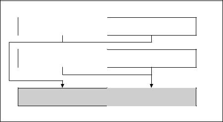
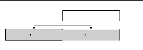
Adds the double-precision floating-point values in the high quadword of the source and destination operands and stores the result in the high quadword of the destination operand.
Subtracts the double-precision floating-point value in the low quadword of the source operand from the low quadword of the destination operand and stores the result in the low quadword of the destination operand. See Figure 3-3.
The source operand can be a 128-bit memory location or an XMM register. The destination operand is an XMM register.
$''68%3' [PP [PP P |
|
|
> @ |
> @ |
[PP P |
|
|
5(68/7 |
[PP > @ [PP P > @ |
[PP > @ [PP P > @ |
|
|
|
[PP |
> @ |
> @ |
|
|
|
20 |
Figure 3-3. ADDSUBPD—Packed Double-FP Add/Subtract |
||
In 64-bit mode, using a REX prefix in the form of REX.R permits this instruction to access additional registers (XMM8-XMM15).
Vol. 2 3-45
INSTRUCTION SET REFERENCE, A-M
Operation
xmm1[63:0] = xmm1[63:0] − xmm2/m128[63:0]; xmm1[127:64] = xmm1[127:64] + xmm2/m128[127:64];
Intel C/C++ Compiler Intrinsic Equivalent
ADDSUBPD |
__m128d _mm_addsub_pd(__m128d a, __m128d b) |
Exceptions
When the source operand is a memory operand, it must be aligned on a 16-byte boundary or a general-protection exception (#GP) will be generated.
SIMD Floating-Point Exceptions
Overflow, Underflow, Invalid, Precision, Denormal.
Protected Mode Exceptions
#GP(0) |
For an illegal memory operand effective address in the CS, DS, |
|
ES, FS or GS segments. |
|
If a memory operand is not aligned on a 16-byte boundary, |
|
regardless of segment. |
#SS(0) |
For an illegal address in the SS segment. |
#PF(fault-code) |
For a page fault. |
#NM |
If CR0.TS[bit 3] = 1. |
#XM |
For an unmasked Streaming SIMD Extensions numeric excep- |
|
tion, CR4.OSXMMEXCPT[bit 10] = 1. |
#UD |
If CR0.EM is 1. |
|
For an unmasked Streaming SIMD Extensions numeric excep- |
|
tion (CR4.OSXMMEXCPT[bit 10] = 0). |
|
If CR4.OSFXSR[bit 9] = 0. |
|
If CPUID.01H:ECX.SSE3[bit 0] = 0. |
Real Address Mode Exceptions
GP(0) |
If any part of the operand would lie outside of the effective |
|
address space from 0 to 0FFFFH. |
|
If a memory operand is not aligned on a 16-byte boundary, |
|
regardless of segment. |
#NM |
If TS bit in CR0 is 1. |
#XM |
For an unmasked Streaming SIMD Extensions numeric excep- |
|
tion, CR4.OSXMMEXCPT[bit 10] = 1. |
3-46 Vol. 2
|
INSTRUCTION SET REFERENCE, A-M |
#UD |
If CR0.EM[bit 2] = 1. |
|
For an unmasked Streaming SIMD Extensions numeric excep- |
|
tion (CR4.OSXMMEXCPT[bit 10] = 0). |
|
If CR4.OSFXSR[bit 9] = 0. |
|
If CPUID.01H:ECX.SSE3[bit 0] = 0. |
Virtual 8086 Mode Exceptions
GP(0) |
If any part of the operand would lie outside of the effective |
|
address space from 0 to 0FFFFH. |
|
If a memory operand is not aligned on a 16-byte boundary, |
|
regardless of segment. |
#NM |
If CR0.TS[bit 3] = 1. |
#XM |
For an unmasked Streaming SIMD Extensions numeric excep- |
|
tion, CR4.OSXMMEXCPT[bit 10] = 1. |
#UD |
If CR0.EM[bit 2] = 1. |
|
For an unmasked Streaming SIMD Extensions numeric excep- |
|
tion (CR4.OSXMMEXCPT[bit 10] = 0). |
|
If CR4.OSFXSR[bit 9] = 0. |
|
If CPUID.01H:ECX.SSE3[bit 0] = 0. |
#PF(fault-code) |
For a page fault. |
Compatibility Mode Exceptions
Same exceptions as in Protected Mode.
64-Bit Mode Exceptions
#SS(0) |
If a memory address referencing the SS segment is in a non- |
|
canonical form. |
#GP(0) |
If the memory address is in a non-canonical form. |
|
If memory operand is not aligned on a 16-byte boundary, |
|
regardless of segment. |
#PF(fault-code) |
For a page fault. |
#NM |
If CR0.TS[bit 3] = 1. |
#XM |
If an unmasked SIMD floating-point exception and CR4.OSXM- |
|
MEXCPT[bit 10] = 1. |
#UD |
If an unmasked SIMD floating-point exception and CR4.OSXM- |
|
MEXCPT[bit 10] = 0. |
|
If CR0.EM[bit 2] = 1. |
|
If CR4.OSFXSR[bit 9] = 0. |
|
If CPUID.01H:ECX.SSE3[bit 0] = 0. |
Vol. 2 3-47
INSTRUCTION SET REFERENCE, A-M
ADDSUBPS—Packed Single-FP Add/Subtract
|
|
64-Bit |
Compat/ |
|
Opcode |
Instruction |
Mode |
Leg Mode |
Description |
F2 0F D0 /r |
ADDSUBPS xmm1, |
Valid |
Valid |
Add/subtract |
|
xmm2/m128 |
|
|
single-precision |
|
|
|
|
floating-point |
|
|
|
|
values from |
|
|
|
|
xmm2/m128 to |
|
|
|
|
xmm1. |
|
|
|
|
|
Description
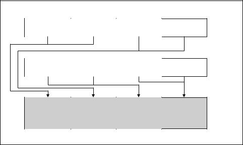
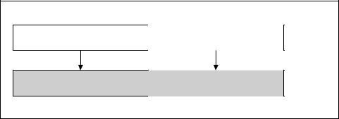
Adds odd-numbered single-precision floating-point values of the source operand (second operand) with the corresponding single-precision floating-point values from the destination operand (first operand); stores the result in the odd-numbered values of the destination operand.
Subtracts the even-numbered single-precision floating-point values in the source operand from the corresponding single-precision floating values in the destination operand; stores the result into the even-numbered values of the destination operand.
The source operand can be a 128-bit memory location or an XMM register. The destination operand is an XMM register. See Figure 3-4.
|
$''68%36 [PP [PP P |
|
|
|
|
|
|
|
[PP |
> @ |
> @ |
> @ |
> @ |
|
|
|
|
|
P |
[PP > @ |
[PP > @ [PP |
[PP > @ |
[PP > @ |
5(68/7 |
[PP P > @ |
P > @ |
[PP P > @ |
[PP P > @ |
[PP |
> @ |
> @ |
> @ |
> @ |
|
|
|
|
|
20 |
Figure 3-4. ADDSUBPS—Packed Single-FP Add/Subtract |
|
|||
In 64-bit mode, using a REX prefix in the form of REX.R permits this instruction to access additional registers (XMM8-XMM15).
3-48 Vol. 2
INSTRUCTION SET REFERENCE, A-M
Operation
xmm1[31:0] = xmm1[31:0] − xmm2/m128[31:0]; xmm1[63:32] = xmm1[63:32] + xmm2/m128[63:32]; xmm1[95:64] = xmm1[95:64] − xmm2/m128[95:64]; xmm1[127:96] = xmm1[127:96] + xmm2/m128[127:96];
Intel C/C++ Compiler Intrinsic Equivalent
ADDSUBPS |
__m128 _mm_addsub_ps(__m128 a, __m128 b) |
Exceptions
When the source operand is a memory operand, the operand must be aligned on a 16-byte boundary or a general-protection exception (#GP) will be generated.
SIMD Floating-Point Exceptions
Overflow, Underflow, Invalid, Precision, Denormal.
Protected Mode Exceptions
#GP(0) |
For an illegal memory operand effective address in the CS, DS, |
|
ES, FS or GS segments. |
|
If a memory operand is not aligned on a 16-byte boundary, |
|
regardless of segment. |
#SS(0) |
For an illegal address in the SS segment. |
#PF(fault-code) |
For a page fault. |
#NM |
If CR0.TS[bit 3] = 1. |
#XM |
For an unmasked Streaming SIMD Extensions numeric excep- |
|
tion, CR4.OSXMMEXCPT[bit 10] = 1. |
#UD |
If CR0.EM[bit 2] = 1. |
|
For an unmasked Streaming SIMD Extensions numeric excep- |
|
tion (CR4.OSXMMEXCPT[bit 10] = 0). |
|
If CR4.OSFXSR[bit 9] = 0. |
|
If CPUID.01H:ECX.SSE3[bit 0] = 0. |
Real Address Mode Exceptions
GP(0) |
If any part of the operand would lie outside of the effective |
|
address space from 0 to 0FFFFH. |
|
If a memory operand is not aligned on a 16-byte boundary, |
|
regardless of segment. |
#NM |
If CR0.TS[bit 3] = 1. |
Vol. 2 3-49
INSTRUCTION SET REFERENCE, A-M
#XM |
For an unmasked Streaming SIMD Extensions numeric excep- |
|
tion, CR4.OSXMMEXCPT[bit 10] = 1. |
#UD |
If CR0.EM[bit 2] = 1. |
|
For an unmasked Streaming SIMD Extensions numeric excep- |
|
tion (CR4.OSXMMEXCPT[bit 10] = 0). |
|
If CR4.OSFXSR[bit 9] = 0. |
|
If CPUID.01H:ECX.SSE3[bit 0] = 0. |
Virtual 8086 Mode Exceptions
GP(0) |
If any part of the operand would lie outside of the effective |
|
address space from 0 to 0FFFFH. |
|
If a memory operand is not aligned on a 16-byte boundary, |
|
regardless of segment. |
#NM |
If CR0.TS[bit 3] = 1. |
#XM |
For an unmasked Streaming SIMD Extensions numeric excep- |
|
tion, CR4.OSXMMEXCPT[bit 10] = 1. |
#UD |
If CR0.EM[bit 2] = 1. |
|
For an unmasked Streaming SIMD Extensions numeric excep- |
|
tion (CR4.OSXMMEXCPT[bit 10] = 0). |
|
If CR4.OSFXSR[bit 9] = 0. |
|
If CPUID.01H:ECX.SSE3[bit 0] = 0. |
#PF(fault-code) |
For a page fault. |
Compatibility Mode Exceptions
Same exceptions as in Protected Mode.
64-Bit Mode Exceptions
#SS(0) |
If a memory address referencing the SS segment is in a non- |
|
canonical form. |
#GP(0) |
If the memory address is in a non-canonical form. |
|
If memory operand is not aligned on a 16-byte boundary, |
|
regardless of segment. |
#PF(fault-code) |
For a page fault. |
#NM |
If CR0.TS[bit 3] = 1. |
#XM |
If an unmasked SIMD floating-point exception and CR4.OSXM- |
|
MEXCPT[bit 10] = 1. |
3-50 Vol. 2
|
INSTRUCTION SET REFERENCE, A-M |
#UD |
If an unmasked SIMD floating-point exception and CR4.OSXM- |
|
MEXCPT[bit 10] = 0. |
|
If CR0.EM[bit 2] = 1. |
|
If CR4.OSFXSR[bit 9] = 0. |
|
If CPUID.01H:ECX.SSE3[bit 0] = 0. |
Vol. 2 3-51

INSTRUCTION SET REFERENCE, A-M
AND—Logical AND
|
|
|
64-Bit |
Comp/Leg |
|
Opcode |
Instruction |
Mode |
Mode |
Description |
|
24 ib |
AND AL, imm8 |
Valid |
Valid |
AL AND imm8. |
|
25 iw |
AND AX, imm16 |
Valid |
Valid |
AX AND imm16. |
|
25 id |
AND EAX, imm32 |
Valid |
Valid |
EAX AND imm32. |
|
REX.W + 25 id |
AND RAX, imm32 |
Valid |
N.E. |
RAX AND imm32 sign- |
|
|
|
|
|
|
extended to 64-bits. |
80 |
/4 ib |
AND r/m8, imm8 |
Valid |
Valid |
r/m8 AND imm8. |
REX + 80 /4 ib |
AND r/m8*, imm8 |
Valid |
N.E. |
r/m64 AND imm8 (sign- |
|
|
|
|
|
|
extended). |
81 |
/4 iw |
AND r/m16, |
Valid |
Valid |
r/m16 AND imm16. |
|
|
imm16 |
|
|
|
81 |
/4 id |
AND r/m32, |
Valid |
Valid |
r/m32 AND imm32. |
|
|
imm32 |
|
|
|
REX.W + 81 /4 |
AND r/m64, |
Valid |
N.E. |
r/m64 AND imm32 sign |
|
id |
|
imm32 |
|
|
extended to 64-bits. |
83 |
/4 ib |
AND r/m16, imm8 |
Valid |
Valid |
r/m16 AND imm8 (sign- |
|
|
|
|
|
extended). |
83 |
/4 ib |
AND r/m32, imm8 |
Valid |
Valid |
r/m32 AND imm8 (sign- |
|
|
|
|
|
extended). |
REX.W + 83 /4 |
AND r/m64, imm8 |
Valid |
N.E. |
r/m64 AND imm8 (sign- |
|
ib |
|
|
|
|
extended). |
20 |
/r |
AND r/m8, r8 |
Valid |
Valid |
r/m8 AND r8. |
REX + 20 /r |
AND r/m8*, r8* |
Valid |
N.E. |
r/m64 AND r8 (sign- |
|
|
|
|
|
|
extended). |
21 |
/r |
AND r/m16, r16 |
Valid |
Valid |
r/m16 AND r16. |
21 |
/r |
AND r/m32, r32 |
Valid |
Valid |
r/m32 AND r32. |
REX.W + 21 /r |
AND r/m64, r64 |
Valid |
N.E. |
r/m64 AND r32. |
|
22 |
/r |
AND r8, r/m8 |
Valid |
Valid |
r8 AND r/m8. |
REX + 22 /r |
AND r8*, r/m8* |
Valid |
N.E. |
r/m64 AND r8 (sign- |
|
|
|
|
|
|
extended). |
23 |
/r |
AND r16, r/m16 |
Valid |
Valid |
r16 AND r/m16. |
23 |
/r |
AND r32, r/m32 |
Valid |
Valid |
r32 AND r/m32. |
REX.W + 23 /r |
AND r64, r/m64 |
Valid |
N.E. |
r64 AND r/m64. |
|
NOTES:
*In 64-bit mode, r/m8 can not be encoded to access the following byte registers if a REX prefix is used: AH, BH, CH, DH.
3-52 Vol. 2
INSTRUCTION SET REFERENCE, A-M
Description
Performs a bitwise AND operation on the destination (first) and source (second) operands and stores the result in the destination operand location. The source operand can be an immediate, a register, or a memory location; the destination operand can be a register or a memory location. (However, two memory operands cannot be used in one instruction.) Each bit of the result is set to 1 if both corresponding bits of the first and second operands are 1; otherwise, it is set to 0.
This instruction can be used with a LOCK prefix to allow the it to be executed atomically.
In 64-bit mode, the instruction’s default operation size is 32 bits. Using a REX prefix in the form of REX.R permits access to additional registers (R8-R15). Using a REX prefix in the form of REX.W promotes operation to 64 bits. See the summary chart at the beginning of this section for encoding data and limits.
Operation
DEST ← DEST AND SRC;
Flags Affected
The OF and CF flags are cleared; the SF, ZF, and PF flags are set according to the result. The state of the AF flag is undefined.
Protected Mode Exceptions
#GP(0) |
If the destination operand points to a non-writable segment. |
|
If a memory operand effective address is outside the CS, DS, |
|
ES, FS, or GS segment limit. |
|
If the DS, ES, FS, or GS register contains a NULL segment |
|
selector. |
#SS(0) |
If a memory operand effective address is outside the SS |
|
segment limit. |
#PF(fault-code) |
If a page fault occurs. |
#AC(0) |
If alignment checking is enabled and an unaligned memory |
|
reference is made while the current privilege level is 3. |
Real-Address Mode Exceptions
#GP |
If a memory operand effective address is outside the CS, DS, |
|
ES, FS, or GS segment limit. |
#SS |
If a memory operand effective address is outside the SS |
|
segment limit. |
Vol. 2 3-53
INSTRUCTION SET REFERENCE, A-M
Virtual-8086 Mode Exceptions
#GP(0) |
If a memory operand effective address is outside the CS, DS, |
|
ES, FS, or GS segment limit. |
#SS(0) |
If a memory operand effective address is outside the SS |
|
segment limit. |
#PF(fault-code) |
If a page fault occurs. |
#AC(0) |
If alignment checking is enabled and an unaligned memory |
|
reference is made. |
Compatibility Mode Exceptions
Same exceptions as in Protected Mode.
64-Bit Mode Exceptions
#SS(0) |
If a memory address referencing the SS segment is in a non- |
|
canonical form. |
#GP(0) |
If the memory address is in a non-canonical form. |
#PF(fault-code) |
If a page fault occurs. |
#AC(0) |
If alignment checking is enabled and an unaligned memory |
|
reference is made while the current privilege level is 3. |
3-54 Vol. 2
INSTRUCTION SET REFERENCE, A-M
ANDPD—Bitwise Logical AND of Packed Double-Precision Floating-
Point Values
|
|
64-Bit |
Compat/ |
|
Opcode |
Instruction |
Mode |
Leg Mode |
Description |
66 0F 54 |
ANDPD xmm1, |
Valid |
Valid |
Bitwise logical AND of xmm2/m128 |
/r |
xmm2/m128 |
|
|
and xmm1. |
|
|
|
|
|
Description
Performs a bitwise logical AND of the two packed double-precision floating-point values from the source operand (second operand) and the destination operand (first operand), and stores the result in the destination operand.
The source operand can be an XMM register or a 128-bit memory location. The destination operand is an XMM register.
In 64-bit mode, using a REX prefix in the form of REX.R permits this instruction to access additional registers (XMM8-XMM15).
Operation
DEST[127:0] ← DEST[127:0] BitwiseAND SRC[127:0];
Intel C/C++ Compiler Intrinsic Equivalent
ANDPD __m128d _mm_and_pd(__m128d a, __m128d b)
SIMD Floating-Point Exceptions
None.
Protected Mode Exceptions
#GP(0) |
For an illegal memory operand effective address in the CS, DS, |
|
ES, FS or GS segments. |
|
If a memory operand is not aligned on a 16-byte boundary, |
|
regardless of segment. |
#SS(0) |
For an illegal address in the SS segment. |
#PF(fault-code) |
For a page fault. |
#NM |
If CR0.TS[bit 3] = 1. |
#UD |
If CR0.EM[bit 2] = 1. |
|
If CR4.OSFXSR[bit 9] = 0. |
|
If CPUID.01H:EDX.SSE2[bit 26] = 0. |
Vol. 2 3-55
INSTRUCTION SET REFERENCE, A-M
Real-Address Mode Exceptions
#GP(0) |
If a memory operand is not aligned on a 16-byte boundary, |
|
regardless of segment. |
|
If any part of the operand lies outside the effective address |
|
space from 0 to FFFFH. |
#NM |
If CR0.TS[bit 3] = 1. |
#UD |
If CR0.EM[bit 2] = 1. |
|
If CR4.OSFXSR[bit 9] = 0. |
|
If CPUID.01H:EDX.SSE2[bit 26] = 0. |
Virtual-8086 Mode Exceptions
Same exceptions as in Real Address Mode #PF(fault-code) For a page fault.
Compatibility Mode Exceptions
Same exceptions as in Protected Mode.
64-Bit Mode Exceptions
#SS(0) |
If a memory address referencing the SS segment is in a non- |
|
canonical form. |
#GP(0) |
If the memory address is in a non-canonical form. |
|
If memory operand is not aligned on a 16-byte boundary, |
|
regardless of segment. |
#PF(fault-code) |
For a page fault. |
#NM |
If CR0.TS[bit 3] = 1. |
#UD |
If CR0.EM[bit 2] = 1. |
|
If CR4.OSFXSR[bit 9] = 0. |
|
If CPUID.01H:EDX.SSE2[bit 26] = 0. |
3-56 Vol. 2
INSTRUCTION SET REFERENCE, A-M
ANDPS—Bitwise Logical AND of Packed Single-Precision Floating-Point
Values
|
|
64-Bit |
Compat/ |
|
Opcode |
Instruction |
Mode |
Leg Mode |
Description |
0F 54 /r |
ANDPS xmm1, |
Valid |
Valid |
Bitwise logical AND of |
|
xmm2/m128 |
|
|
xmm2/m128 and xmm1. |
|
|
|
|
|
Description
Performs a bitwise logical AND of the four packed single-precision floating-point values from the source operand (second operand) and the destination operand (first operand), and stores the result in the destination operand.
The source operand can be an XMM register or a 128-bit memory location. The destination operand is an XMM register.
In 64-bit mode, using a REX prefix in the form of REX.R permits this instruction to access additional registers (XMM8-XMM15).
Operation
DEST[127:0] ← DEST[127:0] BitwiseAND SRC[127:0];
Intel C/C++ Compiler Intrinsic Equivalent
ANDPS __m128 _mm_and_ps(__m128 a, __m128 b)
SIMD Floating-Point Exceptions
None.
Protected Mode Exceptions
#GP(0) |
For an illegal memory operand effective address in the CS, DS, |
|
ES, FS or GS segments. |
|
If a memory operand is not aligned on a 16-byte boundary, |
|
regardless of segment. |
#SS(0) |
For an illegal address in the SS segment. |
#PF(fault-code) |
For a page fault. |
#NM |
If CR0.TS[bit 3] = 1. |
#UD |
If CR0.EM[bit 2] = 1. |
|
If CR4.OSFXSR[bit 9] = 0. |
|
If CPUID.01H:EDX.SSE[bit 25] = 0. |
Vol. 2 3-57
INSTRUCTION SET REFERENCE, A-M
Real-Address Mode Exceptions
#GP(0) |
If a memory operand is not aligned on a 16-byte boundary, |
|
regardless of segment. |
|
If any part of the operand lies outside the effective address |
|
space from 0 to FFFFH. |
#NM |
If CR0.TS[bit 3] = 1. |
#UD |
If CR0.EM[bit 2] = 1. |
|
If CR4.OSFXSR[bit 9] = 0. |
|
If CPUID.01H:EDX.SSE[bit 25] = 0. |
Virtual-8086 Mode Exceptions
Same exceptions as in Real Address Mode #PF(fault-code) For a page fault.
Compatibility Mode Exceptions
Same exceptions as in Protected Mode.
64-Bit Mode Exceptions
#SS(0) |
If a memory address referencing the SS segment is in a non- |
|
canonical form. |
#GP(0) |
If the memory address is in a non-canonical form. |
|
If memory operand is not aligned on a 16-byte boundary, |
|
regardless of segment. |
#PF(fault-code) |
For a page fault. |
#NM |
If CR0.TS[bit 3] = 1. |
#UD |
If CR0.EM[bit 2] = 1. |
|
If CR4.OSFXSR[bit 9] = 0. |
|
If CPUID.01H:EDX.SSE[bit 25] = 0. |
3-58 Vol. 2
INSTRUCTION SET REFERENCE, A-M
ANDNPD—Bitwise Logical AND NOT of Packed Double-Precision
Floating-Point Values
|
|
64-Bit |
Compat/ |
|
Opcode |
Instruction |
Mode |
Leg Mode |
Description |
66 0F 55 /r |
ANDNPD xmm1, xmm2/m128 |
Valid |
Valid |
Bitwise logical AND |
|
|
|
|
NOT of xmm2/m128 |
|
|
|
|
and xmm1. |
|
|
|
|
|
Description
Inverts the bits of the two packed double-precision floating-point values in the destination operand (first operand), performs a bitwise logical AND of the two packed double-precision floating-point values in the source operand (second operand) and the temporary inverted result, and stores the result in the destination operand.
The source operand can be an XMM register or a 128-bit memory location. The destination operand is an XMM register.
In 64-bit mode, using a REX prefix in the form of REX.R permits this instruction to access additional registers (XMM8-XMM15).
Operation
DEST[127:0] ← (NOT(DEST[127:0])) BitwiseAND (SRC[127:0]);
Intel C/C++ Compiler Intrinsic Equivalent
ANDNPD __m128d _mm_andnot_pd(__m128d a, __m128d b)
SIMD Floating-Point Exceptions
None.
Protected Mode Exceptions
#GP(0) |
For an illegal memory operand effective address in the CS, DS, |
|
ES, FS or GS segments. |
|
If a memory operand is not aligned on a 16-byte boundary, |
|
regardless of segment. |
#SS(0) |
For an illegal address in the SS segment. |
#PF(fault-code) |
For a page fault. |
#NM |
If CR0.TS[bit 3] = 1. |
#UD |
If CR0.EM[bit 2] = 1. |
|
If CR4.OSFXSR[bit 9] = 0. |
|
If CPUID.01H:EDX.SSE2[bit 26] = 0. |
Vol. 2 3-59
INSTRUCTION SET REFERENCE, A-M
Real-Address Mode Exceptions
#GP(0) |
If a memory operand is not aligned on a 16-byte boundary, |
|
regardless of segment. |
|
If any part of the operand lies outside the effective address |
|
space from 0 to FFFFH. |
#NM |
If CR0.TS[bit 3] = 1. |
#UD |
If CR0.EM[bit 2] = 1. |
|
If CR4.OSFXSR[bit 9] = 0. |
|
If CPUID.01H:EDX.SSE2[bit 26] = 0. |
Virtual-8086 Mode Exceptions
Same exceptions as in Real Address Mode #PF(fault-code) For a page fault.
Compatibility Mode Exceptions
Same exceptions as in Protected Mode.
64-Bit Mode Exceptions
#SS(0) |
If a memory address referencing the SS segment is in a non- |
|
canonical form. |
#GP(0) |
If the memory address is in a non-canonical form. |
|
If memory operand is not aligned on a 16-byte boundary, |
|
regardless of segment. |
#PF(fault-code) |
For a page fault. |
#NM |
If CR0.TS[bit 3] = 1. |
#UD |
If CR0.EM[bit 2] = 1. |
|
If CR4.OSFXSR[bit 9] = 0. |
|
If CPUID.01H:EDX.SSE2[bit 26] = 0. |
3-60 Vol. 2
INSTRUCTION SET REFERENCE, A-M
ANDNPS—Bitwise Logical AND NOT of Packed Single-Precision
Floating-Point Values
|
|
64-Bit |
Compat/ |
|
Opcode |
Instruction |
Mode |
Leg Mode |
Description |
0F 55 /r |
ANDNPS xmm1, |
Valid |
Valid |
Bitwise logical AND NOT of |
|
xmm2/m128 |
|
|
xmm2/m128 and xmm1. |
|
|
|
|
|
Description
Inverts the bits of the four packed single-precision floating-point values in the destination operand (first operand), performs a bitwise logical AND of the four packed single-precision floating-point values in the source operand (second operand) and the temporary inverted result, and stores the result in the destination operand.
The source operand can be an XMM register or a 128-bit memory location. The destination operand is an XMM register.
In 64-bit mode, using a REX prefix in the form of REX.R permits this instruction to access additional registers (XMM8-XMM15).
Operation
DEST[127:0] ← (NOT(DEST[127:0])) BitwiseAND (SRC[127:0]);
Intel C/C++ Compiler Intrinsic Equivalent
ANDNPS __m128 _mm_andnot_ps(__m128 a, __m128 b)
SIMD Floating-Point Exceptions
None.
Protected Mode Exceptions
#GP(0) |
For an illegal memory operand effective address in the CS, DS, |
|
ES, FS or GS segments. |
|
If a memory operand is not aligned on a 16-byte boundary, |
|
regardless of segment. |
#SS(0) |
For an illegal address in the SS segment. |
#PF(fault-code) |
For a page fault. |
#NM |
If CR0.TS[bit 3] = 1. |
#UD |
If CR0.EM[bit 2] = 1. |
|
If CR4.OSFXSR[bit 9] = 0. |
|
If CPUID.01H:EDX.SSE[bit 25] = 0. |
Vol. 2 3-61
INSTRUCTION SET REFERENCE, A-M
Real-Address Mode Exceptions
#GP(0) |
If a memory operand is not aligned on a 16-byte boundary, |
|
regardless of segment. |
|
If any part of the operand lies outside the effective address |
|
space from 0 to FFFFH. |
#NM |
If CR0.TS[bit 3] = 1. |
#UD |
If CR0.EM[bit 2] = 1. |
|
If CR4.OSFXSR[bit 9] = 0. |
|
If CPUID.01H:EDX.SSE[bit 25] = 0. |
Virtual-8086 Mode Exceptions
Same exceptions as in Real Address Mode #PF(fault-code) For a page fault.
Compatibility Mode Exceptions
Same exceptions as in Protected Mode.
64-Bit Mode Exceptions
#SS(0) |
If a memory address referencing the SS segment is in a non- |
|
canonical form. |
#GP(0) |
If the memory address is in a non-canonical form. |
|
If memory operand is not aligned on a 16-byte boundary, |
|
regardless of segment. |
#PF(fault-code) |
For a page fault. |
#NM |
If CR0.TS[bit 3] = 1. |
#UD |
If CR0.EM[bit 2] = 1. |
|
If CR4.OSFXSR[bit 9] = 0. |
|
If CPUID.01H:EDX.SSE[bit 25] = 0. |
3-62 Vol. 2
|
|
|
|
INSTRUCTION SET REFERENCE, A-M |
ARPL—Adjust RPL Field of Segment Selector |
|
|||
|
|
|
|
|
|
|
64-Bit |
Compat/ |
|
Opcode |
Instruction |
Mode |
Leg Mode |
Description |
63 /r |
ARPL r/m16, r16 |
N. E. |
Valid |
Adjust RPL of r/m16 to not less |
|
|
|
|
than RPL of r16. |
|
|
|
|
|
Description
Compares the RPL fields of two segment selectors. The first operand (the destination operand) contains one segment selector and the second operand (source operand) contains the other. (The RPL field is located in bits 0 and 1 of each operand.) If the RPL field of the destination operand is less than the RPL field of the source operand, the ZF flag is set and the RPL field of the destination operand is increased to match that of the source operand. Otherwise, the ZF flag is cleared and no change is made to the destination operand. (The destination operand can be a word register or a memory location; the source operand must be a word register.)
The ARPL instruction is provided for use by operating-system procedures (however, it can also be used by applications). It is generally used to adjust the RPL of a segment selector that has been passed to the operating system by an application program to match the privilege level of the application program. Here the segment selector passed to the operating system is placed in the destination operand and segment selector for the application program’s code segment is placed in the source operand. (The RPL field in the source operand represents the privilege level of the application program.) Execution of the ARPL instruction then insures that the RPL of the segment selector received by the operating system is no lower (does not have a higher privilege) than the privilege level of the application program (the segment selector for the application program’s code segment can be read from the stack following a procedure call).
This instruction executes as described in compatibility mode and legacy mode. It is not encodable in 64-bit mode.
See “Checking Caller Access Privileges” in Chapter 3, “Protected-Mode Memory Management,” of the Intel® 64 and IA-32 Architectures Software Developer’s Manual, Volume 3A, for more information about the use of this instruction.
Operation
IF 64-BIT MODE
THEN
See MOVSXD;
ELSE
IF DEST[RPL) < SRC[RPL)
THEN
ZF ← 1;
DEST[RPL) ← SRC[RPL);
Vol. 2 3-63
INSTRUCTION SET REFERENCE, A-M
ELSE
ZF ← 0;
FI;
FI;
Flags Affected
The ZF flag is set to 1 if the RPL field of the destination operand is less than that of the source operand; otherwise, it is set to 0.
Protected Mode Exceptions
#GP(0) |
If the destination is located in a non-writable segment. |
|
If a memory operand effective address is outside the CS, DS, |
|
ES, FS, or GS segment limit. |
|
If the DS, ES, FS, or GS register is used to access memory and it |
|
contains a NULL segment selector. |
#SS(0) |
If a memory operand effective address is outside the SS |
|
segment limit. |
#PF(fault-code) |
If a page fault occurs. |
#AC(0) |
If alignment checking is enabled and an unaligned memory |
|
reference is made while the current privilege level is 3. |
Real-Address Mode Exceptions
#UD The ARPL instruction is not recognized in real-address mode.
Virtual-8086 Mode Exceptions
#UD The ARPL instruction is not recognized in virtual-8086 mode.
Compatibility Mode Exceptions
Same exceptions as in Protected Mode.
64-Bit Mode Exceptions
None.
3-64 Vol. 2
|
|
|
|
INSTRUCTION SET REFERENCE, A-M |
BOUND—Check Array Index Against Bounds |
|
|||
|
|
|
|
|
|
|
64-Bit |
Compat/ |
|
Opcode |
Instruction |
Mode |
Leg Mode |
Description |
62 /r |
BOUND r16, m16&16 |
Invalid |
Valid |
Check if r16 (array index) is |
|
|
|
|
within bounds specified by |
|
|
|
|
m16&16. |
62 /r |
BOUND r32, m32&32 |
Invalid |
Valid |
Check if r32 (array index) is |
|
|
|
|
within bounds specified by |
|
|
|
|
m16&16. |
|
|
|
|
|
Description
BOUND determines if the first operand (array index) is within the bounds of an array specified the second operand (bounds operand). The array index is a signed integer located in a register. The bounds operand is a memory location that contains a pair of signed doubleword-integers (when the operand-size attribute is 32) or a pair of signed word-integers (when the operand-size attribute is 16). The first doubleword (or word) is the lower bound of the array and the second doubleword (or word) is the upper bound of the array. The array index must be greater than or equal to the lower bound and less than or equal to the upper bound plus the operand size in bytes. If the index is not within bounds, a BOUND range exceeded exception (#BR) is signaled. When this exception is generated, the saved return instruction pointer points to the BOUND instruction.
The bounds limit data structure (two words or doublewords containing the lower and upper limits of the array) is usually placed just before the array itself, making the limits addressable via a constant offset from the beginning of the array. Because the address of the array already will be present in a register, this practice avoids extra bus cycles to obtain the effective address of the array bounds.
This instruction executes as described in compatibility mode and legacy mode. It is not valid in 64-bit mode.
Operation
IF 64bit Mode THEN
#UD; ELSE
IF (ArrayIndex < LowerBound OR ArrayIndex > UpperBound) (* Below lower bound or above upper bound *)
THEN #BR; FI;
FI;
Vol. 2 3-65
INSTRUCTION SET REFERENCE, A-M
Flags Affected
None.
Protected Mode Exceptions
#BR |
If the bounds test fails. |
#UD |
If second operand is not a memory location. |
#GP(0) |
If a memory operand effective address is outside the CS, DS, |
|
ES, FS, or GS segment limit. |
|
If the DS, ES, FS, or GS register contains a NULL segment |
|
selector. |
#SS(0) |
If a memory operand effective address is outside the SS |
|
segment limit. |
#PF(fault-code) |
If a page fault occurs. |
#AC(0) |
If alignment checking is enabled and an unaligned memory |
|
reference is made while the current privilege level is 3. |
Real-Address Mode Exceptions
#BR |
If the bounds test fails. |
#UD |
If second operand is not a memory location. |
#GP |
If a memory operand effective address is outside the CS, DS, |
|
ES, FS, or GS segment limit. |
#SS |
If a memory operand effective address is outside the SS |
|
segment limit. |
Virtual-8086 Mode Exceptions
#BR |
If the bounds test fails. |
#UD |
If second operand is not a memory location. |
#GP(0) |
If a memory operand effective address is outside the CS, DS, |
|
ES, FS, or GS segment limit. |
#SS(0) |
If a memory operand effective address is outside the SS |
|
segment limit. |
#PF(fault-code) |
If a page fault occurs. |
#AC(0) |
If alignment checking is enabled and an unaligned memory |
|
reference is made. |
3-66 Vol. 2
INSTRUCTION SET REFERENCE, A-M
Compatibility Mode Exceptions
Same exceptions as in Protected Mode.
64-Bit Mode Exceptions
#UD |
If in 64-bit mode. |
Vol. 2 3-67
INSTRUCTION SET REFERENCE, A-M
BSF—Bit Scan Forward
|
|
64-Bit |
Compat/ |
|
Opcode |
Instruction |
Mode |
Leg Mode |
Description |
0F BC /r |
BSF r16, r/m16 |
Valid |
Valid |
Bit scan forward on r/m16. |
0F BC /r |
BSF r32, r/m32 |
Valid |
Valid |
Bit scan forward on r/m32. |
REX.W + 0F BC |
BSF r64, r/m64 |
Valid |
N.E. |
Bit scan forward on r/m64. |
|
|
|
|
|
Description
Searches the source operand (second operand) for the least significant set bit (1 bit). If a least significant 1 bit is found, its bit index is stored in the destination operand (first operand). The source operand can be a register or a memory location; the destination operand is a register. The bit index is an unsigned offset from bit 0 of the source operand. If the content of the source operand is 0, the content of the destination operand is undefined.
In 64-bit mode, the instruction’s default operation size is 32 bits. Using a REX prefix in the form of REX.R permits access to additional registers (R8-R15). Using a REX prefix in the form of REX.W promotes operation to 64 bits. See the summary chart at the beginning of this section for encoding data and limits.
Operation
IF SRC = 0 THEN
ZF ← 1;
DEST is undefined; ELSE
ZF ← 0; temp ← 0;
WHILE Bit(SRC, temp) = 0 DO
temp ← temp + 1; DEST ← temp;
OD;
FI;
Flags Affected
The ZF flag is set to 1 if all the source operand is 0; otherwise, the ZF flag is cleared. The CF, OF, SF, AF, and PF, flags are undefined.
3-68 Vol. 2
|
INSTRUCTION SET REFERENCE, A-M |
Protected Mode Exceptions |
|
#GP(0) |
If a memory operand effective address is outside the CS, DS, |
|
ES, FS, or GS segment limit. |
|
If the DS, ES, FS, or GS register contains a NULL segment |
|
selector. |
#SS(0) |
If a memory operand effective address is outside the SS |
|
segment limit. |
#PF(fault-code) |
If a page fault occurs. |
#AC(0) |
If alignment checking is enabled and an unaligned memory |
|
reference is made while the current privilege level is 3. |
Real-Address Mode Exceptions |
|
#GP |
If a memory operand effective address is outside the CS, DS, |
|
ES, FS, or GS segment limit. |
#SS |
If a memory operand effective address is outside the SS |
|
segment limit. |
Virtual-8086 Mode Exceptions |
|
#GP(0) |
If a memory operand effective address is outside the CS, DS, |
|
ES, FS, or GS segment limit. |
#SS(0) |
If a memory operand effective address is outside the SS |
|
segment limit. |
#PF(fault-code) |
If a page fault occurs. |
#AC(0) |
If alignment checking is enabled and an unaligned memory |
|
reference is made. |
Compatibility Mode Exceptions
Same exceptions as in Protected Mode.
64-Bit Mode Exceptions
#SS(0) |
If a memory address referencing the SS segment is in a non- |
|
canonical form. |
#GP(0) |
If the memory address is in a non-canonical form. |
#PF(fault-code) |
If a page fault occurs. |
#AC(0) |
If alignment checking is enabled and an unaligned memory |
|
reference is made while the current privilege level is 3. |
Vol. 2 3-69
INSTRUCTION SET REFERENCE, A-M
BSR—Bit Scan Reverse
|
|
64-Bit |
Compat/ |
|
Opcode |
Instruction |
Mode |
Leg Mode |
Description |
0F BD /r |
BSR r16, r/m16 |
Valid |
Valid |
Bit scan reverse on r/m16. |
0F BD /r |
BSR r32, r/m32 |
Valid |
Valid |
Bit scan reverse on r/m32. |
REX.W + 0F BD |
BSR r64, r/m64 |
Valid |
N.E. |
Bit scan reverse on r/m64. |
|
|
|
|
|
Description
Searches the source operand (second operand) for the most significant set bit (1 bit). If a most significant 1 bit is found, its bit index is stored in the destination operand (first operand). The source operand can be a register or a memory location; the destination operand is a register. The bit index is an unsigned offset from bit 0 of the source operand. If the content source operand is 0, the content of the destination operand is undefined.
In 64-bit mode, the instruction’s default operation size is 32 bits. Using a REX prefix in the form of REX.R permits access to additional registers (R8-R15). Using a REX prefix in the form of REX.W promotes operation to 64 bits. See the summary chart at the beginning of this section for encoding data and limits.
Operation
IF SRC = 0 THEN
ZF ← 1;
DEST is undefined; ELSE
ZF ← 0;
temp ← OperandSize – 1; WHILE Bit(SRC, temp) = 0 DO
temp ← temp − 1; DEST ← temp;
OD;
FI;
Flags Affected
The ZF flag is set to 1 if all the source operand is 0; otherwise, the ZF flag is cleared. The CF, OF, SF, AF, and PF, flags are undefined.
3-70 Vol. 2
|
INSTRUCTION SET REFERENCE, A-M |
Protected Mode Exceptions |
|
#GP(0) |
If a memory operand effective address is outside the CS, DS, |
|
ES, FS, or GS segment limit. |
|
If the DS, ES, FS, or GS register contains a NULL segment |
|
selector. |
#SS(0) |
If a memory operand effective address is outside the SS |
|
segment limit. |
#PF(fault-code) |
If a page fault occurs. |
#AC(0) |
If alignment checking is enabled and an unaligned memory |
|
reference is made while the current privilege level is 3. |
Real-Address Mode Exceptions |
|
#GP |
If a memory operand effective address is outside the CS, DS, |
|
ES, FS, or GS segment limit. |
#SS |
If a memory operand effective address is outside the SS |
|
segment limit. |
Virtual-8086 Mode Exceptions |
|
#GP(0) |
If a memory operand effective address is outside the CS, DS, |
|
ES, FS, or GS segment limit. |
#SS(0) |
If a memory operand effective address is outside the SS |
|
segment limit. |
#PF(fault-code) |
If a page fault occurs. |
#AC(0) |
If alignment checking is enabled and an unaligned memory |
|
reference is made. |
Compatibility Mode Exceptions
Same exceptions as in Protected Mode.
64-Bit Mode Exceptions
#SS(0) |
If a memory address referencing the SS segment is in a non- |
|
canonical form. |
#GP(0) |
If the memory address is in a non-canonical form. |
#PF(fault-code) |
If a page fault occurs. |
#AC(0) |
If alignment checking is enabled and an unaligned memory |
|
reference is made while the current privilege level is 3. |
Vol. 2 3-71

INSTRUCTION SET REFERENCE, A-M
BSWAP—Byte Swap
|
|
64-Bit |
Compat/ |
|
Opcode |
Instruction |
Mode |
Leg Mode |
Description |
0F C8+rd |
BSWAP r32 |
Valid* |
Valid |
Reverses the byte order of a |
|
|
|
|
32-bit register. |
REX.W + 0F |
BSWAP r64 |
Valid |
N.E. |
Reverses the byte order of a |
C8+rd |
|
|
|
64-bit register. |
NOTES:
* See IA-32 Architecture Compatibility section below.
Description
Reverses the byte order of a 32-bit or 64-bit (destination) register. This instruction is provided for converting little-endian values to big-endian format and vice versa. To swap bytes in a word value (16-bit register), use the XCHG instruction. When the BSWAP instruction references a 16-bit register, the result is undefined.
In 64-bit mode, the instruction’s default operation size is 32 bits. Using a REX prefix in the form of REX.R permits access to additional registers (R8-R15). Using a REX prefix in the form of REX.W promotes operation to 64 bits. See the summary chart at the beginning of this section for encoding data and limits.
IA-32 Architecture Legacy Compatibility
The BSWAP instruction is not supported on IA-32 processors earlier than the Intel486™ processor family. For compatibility with this instruction, software should include functionally equivalent code for execution on Intel processors earlier than the Intel486 processor family.
Operation
TEMP ← DEST
IF 64-bit mode AND OperandSize = 64
THEN
DEST[7:0] ← TEMP[63:56];
DEST[15:8] ← TEMP[55:48];
DEST[23:16] ← TEMP[47:40];
DEST[31:24] ← TEMP[39:32];
DEST[39:32] ← TEMP[31:24];
DEST[47:40] ← TEMP[23:16];
DEST[55:48] ← TEMP[15:8];
DEST[63:56] ← TEMP[7:0];
ELSE
DEST[7:0] ← TEMP[31:24];
DEST[15:8] ← TEMP[23:16];
3-72 Vol. 2
INSTRUCTION SET REFERENCE, A-M
DEST[23:16] ← TEMP[15:8];
DEST[31:24] ← TEMP[7:0];
FI;
Flags Affected
None.
Exceptions (All Operating Modes)
None.
Vol. 2 3-73
INSTRUCTION SET REFERENCE, A-M
BT—Bit Test
|
|
|
64-Bit |
Compat/ |
|
Opcode |
Instruction |
Mode |
Leg Mode |
Description |
|
0F |
A3 |
BT r/m16, r16 |
Valid |
Valid |
Store selected bit in CF |
|
|
|
|
|
flag. |
0F |
A3 |
BT r/m32, r32 |
Valid |
Valid |
Store selected bit in CF |
|
|
|
|
|
flag. |
REX.W + 0F A3 |
BT r/m64, r64 |
Valid |
N.E. |
Store selected bit in CF |
|
|
|
|
|
|
flag. |
0F |
BA /4 ib |
BT r/m16, |
Valid |
Valid |
Store selected bit in CF |
|
|
imm8 |
|
|
flag. |
0F |
BA /4 ib |
BT r/m32, |
Valid |
Valid |
Store selected bit in CF |
|
|
imm8 |
|
|
flag. |
REX.W + 0F BA /4 ib |
BT r/m64, |
Valid |
N.E. |
Store selected bit in CF |
|
|
|
imm8 |
|
|
flag. |
|
|
|
|
|
|
Description
Selects the bit in a bit string (specified with the first operand, called the bit base) at the bit-position designated by the bit offset (specified by the second operand) and stores the value of the bit in the CF flag. The bit base operand can be a register or a memory location; the bit offset operand can be a register or an immediate value:
•If the bit base operand specifies a register, the instruction takes the modulo 16, 32, or 64 of the bit offset operand (modulo size depends on the mode and register size; 64-bit operands are available only in 64-bit mode).
•If the bit base operand specifies a memory location, the operand represents the address of the byte in memory that contains the bit base (bit 0 of the specified byte) of the bit string. The range of the bit position that can be referenced by the offset operand depends on the operand size.
See also: Bit(BitBase, BitOffset) on page 3-10.
Some assemblers support immediate bit offsets larger than 31 by using the immediate bit offset field in combination with the displacement field of the memory operand. In this case, the low-order 3 or 5 bits (3 for 16-bit operands, 5 for 32-bit operands) of the immediate bit offset are stored in the immediate bit offset field, and the high-order bits are shifted and combined with the byte displacement in the addressing mode by the assembler. The processor will ignore the high order bits if they are not zero.
When accessing a bit in memory, the processor may access 4 bytes starting from the memory address for a 32-bit operand size, using by the following relationship:
Effective Address + (4 (BitOffset DIV 32))
3-74 Vol. 2
INSTRUCTION SET REFERENCE, A-M
Or, it may access 2 bytes starting from the memory address for a 16-bit operand, using this relationship:
Effective Address + (2 (BitOffset DIV 16))
It may do so even when only a single byte needs to be accessed to reach the given bit. When using this bit addressing mechanism, software should avoid referencing areas of memory close to address space holes. In particular, it should avoid references to memory-mapped I/O registers. Instead, software should use the MOV instructions to load from or store to these addresses, and use the register form of these instructions to manipulate the data.
In 64-bit mode, the instruction’s default operation size is 32 bits. Using a REX prefix in the form of REX.R permits access to additional registers (R8-R15). Using a REX prefix in the form of REX.W promotes operation to 64 bit operands. See the summary chart at the beginning of this section for encoding data and limits.
Operation
CF ← Bit(BitBase, BitOffset);
Flags Affected
The CF flag contains the value of the selected bit. The OF, SF, ZF, AF, and PF flags are undefined.
Protected Mode Exceptions
#GP(0) |
If a memory operand effective address is outside the CS, DS, |
|
ES, FS, or GS segment limit. |
|
If the DS, ES, FS, or GS register contains a NULL segment |
|
selector. |
#SS(0) |
If a memory operand effective address is outside the SS |
|
segment limit. |
#PF(fault-code) |
If a page fault occurs. |
#AC(0) |
If alignment checking is enabled and an unaligned memory |
|
reference is made while the current privilege level is 3. |
Real-Address Mode Exceptions
#GP |
If a memory operand effective address is outside the CS, DS, |
|
ES, FS, or GS segment limit. |
#SS |
If a memory operand effective address is outside the SS |
|
segment limit. |
Vol. 2 3-75
INSTRUCTION SET REFERENCE, A-M
Virtual-8086 Mode Exceptions
#GP(0) |
If a memory operand effective address is outside the CS, DS, |
|
ES, FS, or GS segment limit. |
#SS(0) |
If a memory operand effective address is outside the SS |
|
segment limit. |
#PF(fault-code) |
If a page fault occurs. |
#AC(0) |
If alignment checking is enabled and an unaligned memory |
|
reference is made. |
Compatibility Mode Exceptions
Same exceptions as in Protected Mode.
64-Bit Mode Exceptions
#SS(0) |
If a memory address referencing the SS segment is in a non- |
|
canonical form. |
#GP(0) |
If the memory address is in a non-canonical form. |
#PF(fault-code) |
If a page fault occurs. |
#AC(0) |
If alignment checking is enabled and an unaligned memory |
|
reference is made while the current privilege level is 3. |
3-76 Vol. 2
INSTRUCTION SET REFERENCE, A-M
BTC—Bit Test and Complement
|
|
|
64- |
|
|
|
|
|
Bit |
Compat/ |
|
Opcode |
Instruction |
Mode |
Leg Mode |
Description |
|
0F |
BB |
BTC r/m16, r16 |
Valid |
Valid |
Store selected bit in CF |
|
|
|
|
|
flag and complement. |
0F |
BB |
BTC r/m32, r32 |
Valid |
Valid |
Store selected bit in CF |
|
|
|
|
|
flag and complement. |
REX.W + 0F BB |
BTC r/m64, r64 |
Valid |
N.E. |
Store selected bit in CF |
|
|
|
|
|
|
flag and complement. |
0F |
BA /7 ib |
BTC r/m16, imm8 |
Valid |
Valid |
Store selected bit in CF |
|
|
|
|
|
flag and complement. |
0F |
BA /7 ib |
BTC r/m32, imm8 |
Valid |
Valid |
Store selected bit in CF |
|
|
|
|
|
flag and complement. |
REX.W + 0F BA /7 ib |
BTC r/m64, imm8 |
Valid |
N.E. |
Store selected bit in CF |
|
|
|
|
|
|
flag and complement. |
|
|
|
|
|
|
Description
Selects the bit in a bit string (specified with the first operand, called the bit base) at the bit-position designated by the bit offset operand (second operand), stores the value of the bit in the CF flag, and complements the selected bit in the bit string. The bit base operand can be a register or a memory location; the bit offset operand can be a register or an immediate value:
•If the bit base operand specifies a register, the instruction takes the modulo 16, 32, or 64 of the bit offset operand (modulo size depends on the mode and register size; 64-bit operands are available only in 64-bit mode). This allows any bit position to be selected.
•If the bit base operand specifies a memory location, the operand represents the address of the byte in memory that contains the bit base (bit 0 of the specified byte) of the bit string. The range of the bit position that can be referenced by the offset operand depends on the operand size.
See also: Bit(BitBase, BitOffset) on page 3-10.
Some assemblers support immediate bit offsets larger than 31 by using the immediate bit offset field in combination with the displacement field of the memory operand. See “BT—Bit Test” in this chapter for more information on this addressing mechanism.
This instruction can be used with a LOCK prefix to allow the instruction to be executed atomically.
In 64-bit mode, the instruction’s default operation size is 32 bits. Using a REX prefix in the form of REX.R permits access to additional registers (R8-R15). Using a REX
Vol. 2 3-77
INSTRUCTION SET REFERENCE, A-M
prefix in the form of REX.W promotes operation to 64 bits. See the summary chart at the beginning of this section for encoding data and limits.
Operation
CF ← Bit(BitBase, BitOffset);
Bit(BitBase, BitOffset) ← NOT Bit(BitBase, BitOffset);
Flags Affected
The CF flag contains the value of the selected bit before it is complemented. The OF, SF, ZF, AF, and PF flags are undefined.
Protected Mode Exceptions
#GP(0) |
If the destination operand points to a non-writable segment. |
|
If a memory operand effective address is outside the CS, DS, |
|
ES, FS, or GS segment limit. |
|
If the DS, ES, FS, or GS register contains a NULL segment |
|
selector. |
#SS(0) |
If a memory operand effective address is outside the SS |
|
segment limit. |
#PF(fault-code) |
If a page fault occurs. |
#AC(0) |
If alignment checking is enabled and an unaligned memory |
|
reference is made while the current privilege level is 3. |
Real-Address Mode Exceptions
#GP |
If a memory operand effective address is outside the CS, DS, |
|
ES, FS, or GS segment limit. |
#SS |
If a memory operand effective address is outside the SS |
|
segment limit. |
Virtual-8086 Mode Exceptions
#GP(0) |
If a memory operand effective address is outside the CS, DS, |
|
ES, FS, or GS segment limit. |
#SS(0) |
If a memory operand effective address is outside the SS |
|
segment limit. |
#PF(fault-code) |
If a page fault occurs. |
#AC(0) |
If alignment checking is enabled and an unaligned memory |
|
reference is made. |
Compatibility Mode Exceptions
Same exceptions as in Protected Mode.
3-78 Vol. 2
|
INSTRUCTION SET REFERENCE, A-M |
64-Bit Mode Exceptions |
|
#SS(0) |
If a memory address referencing the SS segment is in a non- |
|
canonical form. |
#GP(0) |
If the memory address is in a non-canonical form. |
#PF(fault-code) |
If a page fault occurs. |
#AC(0) |
If alignment checking is enabled and an unaligned memory |
|
reference is made while the current privilege level is 3. |
Vol. 2 3-79
INSTRUCTION SET REFERENCE, A-M
BTR—Bit Test and Reset
|
|
|
64-Bit |
Compat/ |
|
Opcode |
Instruction |
Mode |
Leg Mode |
Description |
|
0F |
B3 |
BTR r/m16, r16 |
Valid |
Valid |
Store selected bit in CF |
|
|
|
|
|
flag and clear. |
0F |
B3 |
BTR r/m32, r32 |
Valid |
Valid |
Store selected bit in CF |
|
|
|
|
|
flag and clear. |
REX.W + 0F B3 |
BTR r/m64, r64 |
Valid |
N.E. |
Store selected bit in CF |
|
|
|
|
|
|
flag and clear. |
0F |
BA /6 ib |
BTR r/m16, |
Valid |
Valid |
Store selected bit in CF |
|
|
imm8 |
|
|
flag and clear. |
0F |
BA /6 ib |
BTR r/m32, |
Valid |
Valid |
Store selected bit in CF |
|
|
imm8 |
|
|
flag and clear. |
REX.W + 0F BA /6 ib |
BTR r/m64, |
Valid |
N.E. |
Store selected bit in CF |
|
|
|
imm8 |
|
|
flag and clear. |
|
|
|
|
|
|
DESCRIPTION
Selects the bit in a bit string (specified with the first operand, called the bit base) at the bit-position designated by the bit offset operand (second operand), stores the value of the bit in the CF flag, and clears the selected bit in the bit string to 0. The bit base operand can be a register or a memory location; the bit offset operand can be a register or an immediate value:
•If the bit base operand specifies a register, the instruction takes the modulo 16, 32, or 64 of the bit offset operand (modulo size depends on the mode and register size; 64-bit operands are available only in 64-bit mode). This allows any bit position to be selected.
•If the bit base operand specifies a memory location, the operand represents the address of the byte in memory that contains the bit base (bit 0 of the specified byte) of the bit string. The range of the bit position that can be referenced by the offset operand depends on the operand size.
See also: Bit(BitBase, BitOffset) on page 3-10.
Some assemblers support immediate bit offsets larger than 31 by using the immediate bit offset field in combination with the displacement field of the memory operand. See “BT—Bit Test” in this chapter for more information on this addressing mechanism.
This instruction can be used with a LOCK prefix to allow the instruction to be executed atomically.
In 64-bit mode, the instruction’s default operation size is 32 bits. Using a REX prefix in the form of REX.R permits access to additional registers (R8-R15). Using a REX
3-80 Vol. 2
INSTRUCTION SET REFERENCE, A-M
prefix in the form of REX.W promotes operation to 64 bits. See the summary chart at the beginning of this section for encoding data and limits.
Operation
CF ← Bit(BitBase, BitOffset);
Bit(BitBase, BitOffset) ← 0;
Flags Affected
The CF flag contains the value of the selected bit before it is cleared. The OF, SF, ZF, AF, and PF flags are undefined.
Protected Mode Exceptions
#GP(0) |
If the destination operand points to a non-writable segment. |
|
If a memory operand effective address is outside the CS, DS, |
|
ES, FS, or GS segment limit. |
|
If the DS, ES, FS, or GS register contains a NULL segment |
|
selector. |
#SS(0) |
If a memory operand effective address is outside the SS |
|
segment limit. |
#PF(fault-code) |
If a page fault occurs. |
#AC(0) |
If alignment checking is enabled and an unaligned memory |
|
reference is made while the current privilege level is 3. |
Real-Address Mode Exceptions
#GP |
If a memory operand effective address is outside the CS, DS, |
|
ES, FS, or GS segment limit. |
#SS |
If a memory operand effective address is outside the SS |
|
segment limit. |
Virtual-8086 Mode Exceptions
#GP(0) |
If a memory operand effective address is outside the CS, DS, |
|
ES, FS, or GS segment limit. |
#SS(0) |
If a memory operand effective address is outside the SS |
|
segment limit. |
#PF(fault-code) |
If a page fault occurs. |
#AC(0) |
If alignment checking is enabled and an unaligned memory |
|
reference is made. |
Compatibility Mode Exceptions
Same exceptions as in Protected Mode.
Vol. 2 3-81
INSTRUCTION SET REFERENCE, A-M
64-Bit Mode Exceptions
#SS(0) |
If a memory address referencing the SS segment is in a non- |
|
canonical form. |
#GP(0) |
If the memory address is in a non-canonical form. |
#PF(fault-code) |
If a page fault occurs. |
#AC(0) |
If alignment checking is enabled and an unaligned memory |
|
reference is made while the current privilege level is 3. |
3-82 Vol. 2
INSTRUCTION SET REFERENCE, A-M
BTS—Bit Test and Set
|
|
|
64-Bit |
Compat/ |
|
Opcode |
Instruction |
Mode |
Leg Mode |
Description |
|
0F |
AB |
BTS r/m16, r16 |
Valid |
Valid |
Store selected bit in CF |
|
|
|
|
|
flag and set. |
0F |
AB |
BTS r/m32, r32 |
Valid |
Valid |
Store selected bit in CF |
|
|
|
|
|
flag and set. |
REX.W + 0F AB |
BTS r/m64, r64 |
Valid |
N.E. |
Store selected bit in CF |
|
|
|
|
|
|
flag and set. |
0F |
BA /5 ib |
BTS r/m16, imm8 |
Valid |
Valid |
Store selected bit in CF |
|
|
|
|
|
flag and set. |
0F |
BA /5 ib |
BTS r/m32, imm8 |
Valid |
Valid |
Store selected bit in CF |
|
|
|
|
|
flag and set. |
REX.W + 0F BA /5 ib |
BTS r/m64, imm8 |
Valid |
N.E. |
Store selected bit in CF |
|
|
|
|
|
|
flag and set. |
|
|
|
|
|
|
Description
Selects the bit in a bit string (specified with the first operand, called the bit base) at the bit-position designated by the bit offset operand (second operand), stores the value of the bit in the CF flag, and sets the selected bit in the bit string to 1. The bit base operand can be a register or a memory location; the bit offset operand can be a register or an immediate value:
•If the bit base operand specifies a register, the instruction takes the modulo 16, 32, or 64 of the bit offset operand (modulo size depends on the mode and register size; 64-bit operands are available only in 64-bit mode). This allows any bit position to be selected.
•If the bit base operand specifies a memory location, the operand represents the address of the byte in memory that contains the bit base (bit 0 of the specified byte) of the bit string. The range of the bit position that can be referenced by the offset operand depends on the operand size.
See also: Bit(BitBase, BitOffset) on page 3-10.
Some assemblers support immediate bit offsets larger than 31 by using the immediate bit offset field in combination with the displacement field of the memory operand. See “BT—Bit Test” in this chapter for more information on this addressing mechanism.
This instruction can be used with a LOCK prefix to allow the instruction to be executed atomically.
In 64-bit mode, the instruction’s default operation size is 32 bits. Using a REX prefix in the form of REX.R permits access to additional registers (R8-R15). Using a REX prefix in the form of REX.W promotes operation to 64 bits. See the summary chart at the beginning of this section for encoding data and limits.
Vol. 2 3-83
INSTRUCTION SET REFERENCE, A-M
Operation
CF ← Bit(BitBase, BitOffset);
Bit(BitBase, BitOffset) ← 1;
Flags Affected
The CF flag contains the value of the selected bit before it is set. The OF, SF, ZF, AF, and PF flags are undefined.
Protected Mode Exceptions
#GP(0) |
If the destination operand points to a non-writable segment. |
|
If a memory operand effective address is outside the CS, DS, |
|
ES, FS, or GS segment limit. |
|
If the DS, ES, FS, or GS register contains a NULL segment |
|
selector. |
#SS(0) |
If a memory operand effective address is outside the SS |
|
segment limit. |
#PF(fault-code) |
If a page fault occurs. |
#AC(0) |
If alignment checking is enabled and an unaligned memory |
|
reference is made while the current privilege level is 3. |
Real-Address Mode Exceptions
#GP |
If a memory operand effective address is outside the CS, DS, |
|
ES, FS, or GS segment limit. |
#SS |
If a memory operand effective address is outside the SS |
|
segment limit. |
Virtual-8086 Mode Exceptions
#GP |
If a memory operand effective address is outside the CS, DS, |
|
ES, FS, or GS segment limit. |
#SS |
If a memory operand effective address is outside the SS |
|
segment limit. |
#PF(fault-code) |
If a page fault occurs. |
#AC(0) |
If alignment checking is enabled and an unaligned memory |
|
reference is made. |
Compatibility Mode Exceptions
Same exceptions as in Protected Mode.
3-84 Vol. 2
|
INSTRUCTION SET REFERENCE, A-M |
64-Bit Mode Exceptions |
|
#SS(0) |
If a memory address referencing the SS segment is in a non- |
|
canonical form. |
#GP(0) |
If the memory address is in a non-canonical form. |
#PF(fault-code) |
If a page fault occurs. |
#AC(0) |
If alignment checking is enabled and an unaligned memory |
|
reference is made while the current privilege level is 3. |
Vol. 2 3-85
INSTRUCTION SET REFERENCE, A-M
CALL—Call Procedure
|
|
64-Bit |
Compat/ |
|
Opcode |
Instruction |
Mode |
Leg Mode |
Description |
E8 cw |
CALL rel16 |
N.S. |
Valid |
Call near, relative, displacement |
|
|
|
|
relative to next instruction. |
E8 cd |
CALL rel32 |
Valid |
Valid |
Call near, relative, displacement |
|
|
|
|
relative to next instruction. 32-bit |
|
|
|
|
displacement sign extended to 64- |
|
|
|
|
bits in 64-bit mode. |
FF /2 |
CALL r/m16 |
N.E. |
Valid |
Call near, absolute indirect, address |
|
|
|
|
given in r/m16. |
FF /2 |
CALL r/m32 |
N.E. |
Valid |
Call near, absolute indirect, address |
|
|
|
|
given in r/m32. |
FF /2 |
CALL r/m64 |
Valid |
N.E. |
Call near, absolute indirect, address |
|
|
|
|
given in r/m64. |
9A cd |
CALL |
Invalid |
Valid |
Call far, absolute, address given in |
|
ptr16:16 |
|
|
operand. |
9A cp |
CALL |
Invalid |
Valid |
Call far, absolute, address given in |
|
ptr16:32 |
|
|
operand. |
FF /3 |
CALL |
Valid |
Valid |
Call far, absolute indirect address |
|
m16:16 |
|
|
given in m16:16. |
|
|
|
|
In 32-bit mode: if selector points to a |
|
|
|
|
gate, then RIP = 32-bit zero extended |
|
|
|
|
displacement taken from gate; else |
|
|
|
|
RIP = zero extended 16-bit offset |
|
|
|
|
from far pointer referenced in the |
|
|
|
|
instruction. |
FF /3 |
CALL |
Valid |
Valid |
In 64-bit mode: If selector points to a |
|
m16:32 |
|
|
gate, then RIP = 64-bit displacement |
|
|
|
|
taken from gate; else RIP = zero |
|
|
|
|
extended 32-bit offset from far |
|
|
|
|
pointer referenced in the instruction. |
REX.W + FF /3 |
CALL |
Valid |
N.E. |
In 64-bit mode: If selector points to a |
|
m16:64 |
|
|
gate, then RIP = 64-bit displacement |
|
|
|
|
taken from gate; else RIP = 64-bit |
|
|
|
|
offset from far pointer referenced in |
|
|
|
|
the instruction. |
|
|
|
|
|
Description
Saves procedure linking information on the stack and branches to the called procedure specified using the target operand. The target operand specifies the address of the first instruction in the called procedure. The operand can be an immediate value, a general-purpose register, or a memory location.
3-86 Vol. 2
INSTRUCTION SET REFERENCE, A-M
This instruction can be used to execute four types of calls:
•Near Call — A call to a procedure in the current code segment (the segment currently pointed to by the CS register), sometimes referred to as an intrasegment call.
•Far Call — A call to a procedure located in a different segment than the current code segment, sometimes referred to as an inter-segment call.
•Inter-privilege-level far call — A far call to a procedure in a segment at a different privilege level than that of the currently executing program or procedure.
•Task switch — A call to a procedure located in a different task.
The latter two call types (inter-privilege-level call and task switch) can only be executed in protected mode. See “Calling Procedures Using Call and RET” in Chapter 6 of the Intel® 64 and IA-32 Architectures Software Developer’s Manual, Volume 1, for additional information on near, far, and inter-privilege-level calls. See Chapter 6, “Task Management,” in the Intel® 64 and IA-32 Architectures Software Developer’s Manual, Volume 3A, for information on performing task switches with the CALL instruction.
Near Call. When executing a near call, the processor pushes the value of the EIP register (which contains the offset of the instruction following the CALL instruction) on the stack (for use later as a return-instruction pointer). The processor then branches to the address in the current code segment specified by the target operand. The target operand specifies either an absolute offset in the code segment (an offset from the base of the code segment) or a relative offset (a signed displacement relative to the current value of the instruction pointer in the EIP register; this value points to the instruction following the CALL instruction). The CS register is not changed on near calls.
For a near call absolute, an absolute offset is specified indirectly in a general-purpose register or a memory location (r/m16, r/m32, or r/m64). The operand-size attribute determines the size of the target operand (16, 32 or 64 bits). When in 64-bit mode, the operand size for near call (and all near branches) is forced to 64-bits. Absolute offsets are loaded directly into the EIP(RIP) register. If the operand size attribute is 16, the upper two bytes of the EIP register are cleared, resulting in a maximum instruction pointer size of 16 bits. When accessing an absolute offset indirectly using the stack pointer [ESP] as the base register, the base value used is the value of the ESP before the instruction executes.
A relative offset (rel16 or rel32) is generally specified as a label in assembly code. But at the machine code level, it is encoded as a signed, 16or 32-bit immediate value. This value is added to the value in the EIP(RIP) register. In 64-bit mode the relative offset is always a 32-bit immediate value which is sign extended to 64-bits before it is added to the value in the RIP register for the target calculation. As with absolute offsets, the operand-size attribute determines the size of the target operand (16, 32, or 64 bits). In 64-bit mode the target operand will always be 64-bits because the operand size is forced to 64-bits for near branches.
Far Calls in Real-Address or Virtual-8086 Mode. When executing a far call in realaddress or virtual-8086 mode, the processor pushes the current value of both the CS
Vol. 2 3-87
INSTRUCTION SET REFERENCE, A-M
and EIP registers on the stack for use as a return-instruction pointer. The processor then performs a “far branch” to the code segment and offset specified with the target operand for the called procedure. The target operand specifies an absolute far address either directly with a pointer (ptr16:16 or ptr16:32) or indirectly with a memory location (m16:16 or m16:32). With the pointer method, the segment and offset of the called procedure is encoded in the instruction using a 4-byte (16-bit operand size) or 6-byte (32-bit operand size) far address immediate. With the indirect method, the target operand specifies a memory location that contains a 4-byte (16-bit operand size) or 6-byte (32-bit operand size) far address. The operand-size attribute determines the size of the offset (16 or 32 bits) in the far address. The far address is loaded directly into the CS and EIP registers. If the operand-size attribute is 16, the upper two bytes of the EIP register are cleared.
Far Calls in Protected Mode. When the processor is operating in protected mode, the CALL instruction can be used to perform the following types of far calls:
•Far call to the same privilege level
•Far call to a different privilege level (inter-privilege level call)
•Task switch (far call to another task)
In protected mode, the processor always uses the segment selector part of the far address to access the corresponding descriptor in the GDT or LDT. The descriptor type (code segment, call gate, task gate, or TSS) and access rights determine the type of call operation to be performed.
If the selected descriptor is for a code segment, a far call to a code segment at the same privilege level is performed. (If the selected code segment is at a different privilege level and the code segment is non-conforming, a general-protection exception is generated.) A far call to the same privilege level in protected mode is very similar to one carried out in real-address or virtual-8086 mode. The target operand specifies an absolute far address either directly with a pointer (ptr16:16 or ptr16:32) or indirectly with a memory location (m16:16 or m16:32). The operandsize attribute determines the size of the offset (16 or 32 bits) in the far address. The new code segment selector and its descriptor are loaded into CS register; the offset from the instruction is loaded into the EIP register.
A call gate (described in the next paragraph) can also be used to perform a far call to a code segment at the same privilege level. Using this mechanism provides an extra level of indirection and is the preferred method of making calls between 16-bit and 32-bit code segments.
When executing an inter-privilege-level far call, the code segment for the procedure being called must be accessed through a call gate. The segment selector specified by the target operand identifies the call gate. The target operand can specify the call gate segment selector either directly with a pointer (ptr16:16 or ptr16:32) or indirectly with a memory location (m16:16 or m16:32). The processor obtains the segment selector for the new code segment and the new instruction pointer (offset) from the call gate descriptor. (The offset from the target operand is ignored when a call gate is used.)
3-88 Vol. 2
INSTRUCTION SET REFERENCE, A-M
On inter-privilege-level calls, the processor switches to the stack for the privilege level of the called procedure. The segment selector for the new stack segment is specified in the TSS for the currently running task. The branch to the new code segment occurs after the stack switch. (Note that when using a call gate to perform a far call to a segment at the same privilege level, no stack switch occurs.) On the new stack, the processor pushes the segment selector and stack pointer for the calling procedure’s stack, an optional set of parameters from the calling procedures stack, and the segment selector and instruction pointer for the calling procedure’s code segment. (A value in the call gate descriptor determines how many parameters to copy to the new stack.) Finally, the processor branches to the address of the procedure being called within the new code segment.
Executing a task switch with the CALL instruction is similar to executing a call through a call gate. The target operand specifies the segment selector of the task gate for the new task activated by the switch (the offset in the target operand is ignored). The task gate in turn points to the TSS for the new task, which contains the segment selectors for the task’s code and stack segments. Note that the TSS also contains the EIP value for the next instruction that was to be executed before the calling task was suspended. This instruction pointer value is loaded into the EIP register to re-start the calling task.
The CALL instruction can also specify the segment selector of the TSS directly, which eliminates the indirection of the task gate. See Chapter 6, “Task Management,” in the
Intel® 64 and IA-32 Architectures Software Developer’s Manual, Volume 3A, for information on the mechanics of a task switch.
When you execute at task switch with a CALL instruction, the nested task flag (NT) is set in the EFLAGS register and the new TSS’s previous task link field is loaded with the old task’s TSS selector. Code is expected to suspend this nested task by executing an IRET instruction which, because the NT flag is set, automatically uses the previous task link to return to the calling task. (See “Task Linking” in Chapter 6 of the Intel® 64 and IA-32 Architectures Software Developer’s Manual, Volume 3A, for information on nested tasks.) Switching tasks with the CALL instruction differs in this regard from JMP instruction. JMP does not set the NT flag and therefore does not expect an IRET instruction to suspend the task.
Mixing 16-Bit and 32-Bit Calls. When making far calls between 16-bit and 32-bit code segments, use a call gate. If the far call is from a 32-bit code segment to a 16-bit code segment, the call should be made from the first 64 KBytes of the 32-bit code segment. This is because the operand-size attribute of the instruction is set to 16, so only a 16-bit return address offset can be saved. Also, the call should be made using a 16-bit call gate so that 16-bit values can be pushed on the stack. See Chapter 16, “Mixing 16-Bit and 32-Bit Code,” in the Intel® 64 and IA-32 Architectures Software Developer’s Manual, Volume 3A, for more information.
Far Calls in Compatibility Mode. When the processor is operating in compatibility mode, the CALL instruction can be used to perform the following types of far calls:
•Far call to the same privilege level, remaining in compatibility mode
•Far call to the same privilege level, transitioning to 64-bit mode
Vol. 2 3-89
INSTRUCTION SET REFERENCE, A-M
•Far call to a different privilege level (inter-privilege level call), transitioning to 64bit mode
Note that a CALL instruction can not be used to cause a task switch in compatibility mode since task switches are not supported in IA-32e mode.
In compatibility mode, the processor always uses the segment selector part of the far address to access the corresponding descriptor in the GDT or LDT. The descriptor type (code segment, call gate) and access rights determine the type of call operation to be performed.
If the selected descriptor is for a code segment, a far call to a code segment at the same privilege level is performed. (If the selected code segment is at a different privilege level and the code segment is non-conforming, a general-protection exception is generated.) A far call to the same privilege level in compatibility mode is very similar to one carried out in protected mode. The target operand specifies an absolute far address either directly with a pointer (ptr16:16 or ptr16:32) or indirectly with a memory location (m16:16 or m16:32). The operand-size attribute determines the size of the offset (16 or 32 bits) in the far address. The new code segment selector and its descriptor are loaded into CS register and the offset from the instruction is loaded into the EIP register. The difference is that 64-bit mode may be entered. This specified by the L bit in the new code segment descriptor.
Note that a 64-bit call gate (described in the next paragraph) can also be used to perform a far call to a code segment at the same privilege level. However, using this mechanism requires that the target code segment descriptor have the L bit set, causing an entry to 64-bit mode.
When executing an inter-privilege-level far call, the code segment for the procedure being called must be accessed through a 64-bit call gate. The segment selector specified by the target operand identifies the call gate. The target operand can specify the call gate segment selector either directly with a pointer (ptr16:16 or ptr16:32) or indirectly with a memory location (m16:16 or m16:32). The processor obtains the segment selector for the new code segment and the new instruction pointer (offset) from the 16-byte call gate descriptor. (The offset from the target operand is ignored when a call gate is used.)
On inter-privilege-level calls, the processor switches to the stack for the privilege level of the called procedure. The segment selector for the new stack segment is set to NULL. The new stack pointer is specified in the TSS for the currently running task. The branch to the new code segment occurs after the stack switch. (Note that when using a call gate to perform a far call to a segment at the same privilege level, an implicit stack switch occurs as a result of entering 64-bit mode. The SS selector is unchanged, but stack segment accesses use a segment base of 0x0, the limit is ignored, and the default stack size is 64-bits. The full value of RSP is used for the offset, of which the upper 32-bits are undefined.) On the new stack, the processor pushes the segment selector and stack pointer for the calling procedure’s stack and the segment selector and instruction pointer for the calling procedure’s code segment. (Parameter copy is not supported in IA-32e mode.) Finally, the processor branches to the address of the procedure being called within the new code segment.
3-90 Vol. 2
INSTRUCTION SET REFERENCE, A-M
Near/(Far) Calls in 64-bit Mode. When the processor is operating in 64-bit mode, the CALL instruction can be used to perform the following types of far calls:
•Far call to the same privilege level, transitioning to compatibility mode
•Far call to the same privilege level, remaining in 64-bit mode
•Far call to a different privilege level (inter-privilege level call), remaining in 64-bit mode
Note that in this mode the CALL instruction can not be used to cause a task switch in 64-bit mode since task switches are not supported in IA-32e mode.
In 64-bit mode, the processor always uses the segment selector part of the far address to access the corresponding descriptor in the GDT or LDT. The descriptor type (code segment, call gate) and access rights determine the type of call operation to be performed.
If the selected descriptor is for a code segment, a far call to a code segment at the same privilege level is performed. (If the selected code segment is at a different privilege level and the code segment is non-conforming, a general-protection exception is generated.) A far call to the same privilege level in 64-bit mode is very similar to one carried out in compatibility mode. The target operand specifies an absolute far address indirectly with a memory location (m16:16, m16:32 or m16:64). The form of CALL with a direct specification of absolute far address is not defined in 64-bit mode. The operand-size attribute determines the size of the offset (16, 32, or 64 bits) in the far address. The new code segment selector and its descriptor are loaded into the CS register; the offset from the instruction is loaded into the EIP register. The new code segment may specify entry either into compatibility or 64-bit mode, based on the L bit value.
A 64-bit call gate (described in the next paragraph) can also be used to perform a far call to a code segment at the same privilege level. However, using this mechanism requires that the target code segment descriptor have the L bit set.
When executing an inter-privilege-level far call, the code segment for the procedure being called must be accessed through a 64-bit call gate. The segment selector specified by the target operand identifies the call gate. The target operand can only specify the call gate segment selector indirectly with a memory location (m16:16, m16:32 or m16:64). The processor obtains the segment selector for the new code segment and the new instruction pointer (offset) from the 16-byte call gate descriptor. (The offset from the target operand is ignored when a call gate is used.)
On inter-privilege-level calls, the processor switches to the stack for the privilege level of the called procedure. The segment selector for the new stack segment is set to NULL. The new stack pointer is specified in the TSS for the currently running task. The branch to the new code segment occurs after the stack switch.
Note that when using a call gate to perform a far call to a segment at the same privilege level, an implicit stack switch occurs as a result of entering 64-bit mode. The SS selector is unchanged, but stack segment accesses use a segment base of 0x0, the limit is ignored, and the default stack size is 64-bits. (The full value of RSP is used for the offset.) On the new stack, the processor pushes the segment selector and stack
Vol. 2 3-91
INSTRUCTION SET REFERENCE, A-M
pointer for the calling procedure’s stack and the segment selector and instruction pointer for the calling procedure’s code segment. (Parameter copy is not supported in IA-32e mode.) Finally, the processor branches to the address of the procedure being called within the new code segment.
Operation
IF near call
THEN IF near relative call THEN
IF OperandSize = 64 THEN
tempDEST ← SignExtend(DEST); (* DEST is rel32 *) tempRIP ← RIP + tempDEST;
IF stack not large enough for a 8-byte return address THEN #SS(0); FI;
Push(RIP);
RIP ← tempRIP;
FI;
IF OperandSize = 32 THEN
tempEIP ← EIP + DEST; (* DEST is rel32 *)
IF tempEIP is not within code segment limit THEN #GP(0); FI; IF stack not large enough for a 4-byte return address
THEN #SS(0); FI; Push(EIP);
EIP ← tempEIP;
FI;
IF OperandSize = 16 THEN
tempEIP ← (EIP + DEST) AND 0000FFFFH; (* DEST is rel16 *) IF tempEIP is not within code segment limit THEN #GP(0); FI; IF stack not large enough for a 2-byte return address
THEN #SS(0); FI; Push(IP);
EIP ← tempEIP;
FI;
ELSE (* Near absolute call *) IF OperandSize = 64
THEN
tempRIP ← DEST; (* DEST is r/m64 *)
IF stack not large enough for a 8-byte return address THEN #SS(0); FI;
Push(RIP);
3-92 Vol. 2
INSTRUCTION SET REFERENCE, A-M
RIP ← tempRIP;
FI;
IF OperandSize = 32 THEN
tempEIP ← DEST; (* DEST is r/m32 *)
IF tempEIP is not within code segment limit THEN #GP(0); FI; IF stack not large enough for a 4-byte return address
THEN #SS(0); FI; Push(EIP);
EIP ← tempEIP;
FI;
IF OperandSize = 16 THEN
tempEIP ← DEST AND 0000FFFFH; (* DEST is r/m16 *)
IF tempEIP is not within code segment limit THEN #GP(0); FI; IF stack not large enough for a 2-byte return address
THEN #SS(0); FI; Push(IP);
EIP ← tempEIP;
FI;
FI;rel/abs FI; near
IF far call and (PE = 0 or (PE = 1 and VM = 1)) (* Real-address or virtual-8086 mode *) THEN
IF OperandSize = 32 THEN
IF stack not large enough for a 6-byte return address THEN #SS(0); FI;
IF DEST[31:16] is not zero THEN #GP(0); FI; Push(CS); (* Padded with 16 high-order bits *) Push(EIP);
CS ← DEST[47:32]; (* DEST is ptr16:32 or [m16:32] *) EIP ← DEST[31:0]; (* DEST is ptr16:32 or [m16:32] *)
ELSE (* OperandSize = 16 *)
IF stack not large enough for a 4-byte return address THEN #SS(0); FI;
Push(CS);
Push(IP);
CS ← DEST[31:16]; (* DEST is ptr16:16 or [m16:16] *)
EIP ← DEST[15:0]; (* DEST is ptr16:16 or [m16:16]; clear upper 16 bits *)
FI;
FI;
Vol. 2 3-93
INSTRUCTION SET REFERENCE, A-M
IF far call and (PE = 1 and VM = 0) (* Protected mode or IA-32e Mode, not virtual-8086 mode*) THEN
IF segment selector in target operand NULL THEN #GP(0); FI;
IF segment selector index not within descriptor table limits THEN #GP(new code segment selector); FI;
Read type and access rights of selected segment descriptor; IF IA32_EFER.LMA = 0
THEN
IF segment type is not a conforming or nonconforming code segment, call gate, task gate, or TSS
THEN #GP(segment selector); FI;
ELSE
IF segment type is not a conforming or nonconforming code segment or 64-bit call gate,
THEN #GP(segment selector); FI;
FI;
Depending on type and access rights:
GO TO CONFORMING-CODE-SEGMENT;
GO TO NONCONFORMING-CODE-SEGMENT; GO TO CALL-GATE;
GO TO TASK-GATE;
GO TO TASK-STATE-SEGMENT;
FI;
CONFORMING-CODE-SEGMENT:
IF L-Bit = 1 and D-BIT = 1 and IA32_EFER.LMA = 1 THEN GP(new code segment selector); FI;
IF DPL > CPL
THEN #GP(new code segment selector); FI; IF segment not present
THEN #NP(new code segment selector); FI; IF stack not large enough for return address
THEN #SS(0); FI; tempEIP ← DEST(Offset); IF OperandSize = 16
THEN
tempEIP ← tempEIP AND 0000FFFFH; FI; (* Clear upper 16 bits *)
IF (EFER.LMA = 0 or target mode = Compatibility mode) and (tempEIP outside new code segment limit)
THEN #GP(0); FI;
IF tempEIP is non-canonical
3-94 Vol. 2
INSTRUCTION SET REFERENCE, A-M
THEN #GP(0); FI; IF OperandSize = 32
THEN
Push(CS); (* Padded with 16 high-order bits *) Push(EIP);
CS ← DEST(CodeSegmentSelector);
(* Segment descriptor information also loaded *) CS(RPL) ← CPL;
EIP ← tempEIP; ELSE
IF OperandSize = 16 THEN
Push(CS);
Push(IP);
CS ← DEST(CodeSegmentSelector);
(* Segment descriptor information also loaded *) CS(RPL) ← CPL;
EIP ← tempEIP;
ELSE (* OperandSize = 64 *)
Push(CS); (* Padded with 48 high-order bits *) Push(RIP);
CS ← DEST(CodeSegmentSelector);
(* Segment descriptor information also loaded *) CS(RPL) ← CPL;
RIP ← tempEIP;
FI;
FI;
END;
NONCONFORMING-CODE-SEGMENT:
IF L-Bit = 1 and D-BIT = 1 and IA32_EFER.LMA = 1 THEN GP(new code segment selector); FI;
IF (RPL > CPL) or (DPL ≠ CPL)
THEN #GP(new code segment selector); FI; IF segment not present
THEN #NP(new code segment selector); FI; IF stack not large enough for return address
THEN #SS(0); FI; tempEIP ← DEST(Offset); IF OperandSize = 16
THEN tempEIP ← tempEIP AND 0000FFFFH; FI; (* Clear upper 16 bits *)
IF (EFER.LMA = 0 or target mode = Compatibility mode) and (tempEIP outside new code segment limit)
THEN #GP(0); FI;
Vol. 2 3-95
INSTRUCTION SET REFERENCE, A-M
IF tempEIP is non-canonical THEN #GP(0); FI;
IF OperandSize = 32 THEN
Push(CS); (* Padded with 16 high-order bits *) Push(EIP);
CS ← DEST(CodeSegmentSelector);
(* Segment descriptor information also loaded *) CS(RPL) ← CPL;
EIP ← tempEIP; ELSE
IF OperandSize = 16 THEN
Push(CS);
Push(IP);
CS ← DEST(CodeSegmentSelector);
(* Segment descriptor information also loaded *) CS(RPL) ← CPL;
EIP ← tempEIP;
ELSE (* OperandSize = 64 *)
Push(CS); (* Padded with 48 high-order bits *) Push(RIP);
CS ← DEST(CodeSegmentSelector);
(* Segment descriptor information also loaded *) CS(RPL) ← CPL;
RIP ← tempEIP;
FI;
FI;
END;
CALL-GATE:
IF call gate (DPL < CPL) or (RPL > DPL) THEN #GP(call gate selector); FI;
IF call gate not present
THEN #NP(call gate selector); FI;
IF call gate code-segment selector is NULL THEN #GP(0); FI;
IF call gate code-segment selector index is outside descriptor table limits THEN #GP(code segment selector); FI;
Read code segment descriptor;
IF code-segment segment descriptor does not indicate a code segment or code-segment segment descriptor DPL > CPL
THEN #GP(code segment selector); FI;
3-96 Vol. 2
INSTRUCTION SET REFERENCE, A-M
IF IA32_EFER.LMA = 1 AND (code-segment segment descriptor is
not a 64-bit code segment or code-segment descriptor has both L-Bit and D-bit set) THEN #GP(code segment selector); FI;
IF code segment not present
THEN #NP(new code segment selector); FI; IF code segment is non-conforming and DPL < CPL
THEN go to MORE-PRIVILEGE; ELSE go to SAME-PRIVILEGE;
FI;
END;
MORE-PRIVILEGE:
IF current TSS is 32-bit TSS THEN
TSSstackAddress ← new code segment (DPL 8) + 4; IF (TSSstackAddress + 7) > TSS limit
THEN #TS(current TSS selector); FI; newSS ← TSSstackAddress + 4; newESP ← stack address;
ELSE
IF current TSS is 16-bit TSS THEN
TSSstackAddress ← new code segment (DPL 4) + 2; IF (TSSstackAddress + 4) > TSS limit
THEN #TS(current TSS selector); FI; newESP ← TSSstackAddress;
newSS ← TSSstackAddress + 2; ELSE (* TSS is 64-bit *)
TSSstackAddress ← new code segment (DPL 8) + 4; IF (TSSstackAddress + 8) > TSS limit
THEN #TS(current TSS selector); FI; newESP ← TSSstackAddress;
newSS ← NULL;
FI;
FI;
IF IA32_EFER.LMA = 0 and stack segment selector = NULL THEN #TS(stack segment selector); FI;
Read code segment descriptor;
IF IA32_EFER.LMA = 0 and (stack segment selector's RPL ≠ DPL of code segment
or stack segment DPL ≠ DPL of code segment or stack segment is not a writable data segment)
THEN #TS(SS selector); FI
IF IA32_EFER.LMA = 0 and stack segment not present THEN #SS(SS selector); FI;
Vol. 2 3-97
INSTRUCTION SET REFERENCE, A-M
IF CallGateSize = 32 THEN
IF stack does not have room for parameters plus 16 bytes THEN #SS(SS selector); FI;
IF CallGate(InstructionPointer) not within code segment limit THEN #GP(0); FI;
SS ← newSS;
(* Segment descriptor information also loaded *) ESP ← newESP;
CS:EIP ← CallGate(CS:InstructionPointer);
(* Segment descriptor information also loaded *) Push(oldSS:oldESP); (* From calling procedure *)
temp ← parameter count from call gate, masked to 5 bits; Push(parameters from calling procedure’s stack, temp) Push(oldCS:oldEIP); (* Return address to calling procedure *)
ELSE
IF CallGateSize = 16 THEN
IF stack does not have room for parameters plus 8 bytes THEN #SS(SS selector); FI;
IF (CallGate(InstructionPointer) AND FFFFH) not in code segment limit THEN #GP(0); FI;
SS ← newSS;
(* Segment descriptor information also loaded *) ESP ← newESP;
CS:IP ← CallGate(CS:InstructionPointer);
(* Segment descriptor information also loaded *) Push(oldSS:oldESP); (* From calling procedure *)
temp ← parameter count from call gate, masked to 5 bits; Push(parameters from calling procedure’s stack, temp) Push(oldCS:oldEIP); (* Return address to calling procedure *)
ELSE (* CallGateSize = 64 *)
IF pushing 32 bytes on the stack touches non-canonical addresses THEN #SS(SS selector); FI;
IF (CallGate(InstructionPointer) is non-canonical) THEN #GP(0); FI;
SS ← newSS; (* New SS is NULL) RSP ← newESP;
CS:IP ← CallGate(CS:InstructionPointer);
(* Segment descriptor information also loaded *) Push(oldSS:oldESP); (* From calling procedure *) Push(oldCS:oldEIP); (* Return address to calling procedure *)
FI;
3-98 Vol. 2
INSTRUCTION SET REFERENCE, A-M
FI;
CPL ← CodeSegment(DPL)
CS(RPL) ← CPL
END;
SAME-PRIVILEGE:
IF CallGateSize = 32 THEN
IF stack does not have room for 8 bytes THEN #SS(0); FI;
IF CallGate(InstructionPointer) not within code segment limit THEN #GP(0); FI;
CS:EIP ← CallGate(CS:EIP) (* Segment descriptor information also loaded *) Push(oldCS:oldEIP); (* Return address to calling procedure *)
ELSE
If CallGateSize = 16 THEN
IF stack does not have room for 4 bytes THEN #SS(0); FI;
IF CallGate(InstructionPointer) not within code segment limit THEN #GP(0); FI;
CS:IP ← CallGate(CS:instruction pointer);
(* Segment descriptor information also loaded *) Push(oldCS:oldIP); (* Return address to calling procedure *)
ELSE (* CallGateSize = 64)
IF pushing 16 bytes on the stack touches non-canonical addresses THEN #SS(0); FI;
IF RIP non-canonical THEN #GP(0); FI;
CS:IP ← CallGate(CS:instruction pointer);
(* Segment descriptor information also loaded *) Push(oldCS:oldIP); (* Return address to calling procedure *)
FI;
FI;
CS(RPL) ← CPL END;
TASK-GATE:
IF task gate DPL < CPL or RPL
THEN #GP(task gate selector); FI;
IF task gate not present
THEN #NP(task gate selector); FI;
Read the TSS segment selector in the task-gate descriptor;
Vol. 2 3-99
INSTRUCTION SET REFERENCE, A-M
IF TSS segment selector local/global bit is set to local or index not within GDT limits
THEN #GP(TSS selector); FI; Access TSS descriptor in GDT;
IF TSS descriptor specifies that the TSS is busy (low-order 5 bits set to 00001) THEN #GP(TSS selector); FI;
IF TSS not present
THEN #NP(TSS selector); FI; SWITCH-TASKS (with nesting) to TSS; IF EIP not within code segment limit
THEN #GP(0); FI;
END;
TASK-STATE-SEGMENT:
IF TSS DPL < CPL or RPL
or TSS descriptor indicates TSS not available THEN #GP(TSS selector); FI;
IF TSS is not present
THEN #NP(TSS selector); FI; SWITCH-TASKS (with nesting) to TSS; IF EIP not within code segment limit
THEN #GP(0); FI;
END;
Flags Affected
All flags are affected if a task switch occurs; no flags are affected if a task switch does not occur.
Protected Mode Exceptions
#GP(0) |
If the target offset in destination operand is beyond the new |
|
code segment limit. |
|
If the segment selector in the destination operand is NULL. |
|
If the code segment selector in the gate is NULL. |
|
If a memory operand effective address is outside the CS, DS, |
|
ES, FS, or GS segment limit. |
|
If the DS, ES, FS, or GS register is used to access memory and it |
|
contains a NULL segment selector. |
#GP(selector) |
If a code segment or gate or TSS selector index is outside |
|
descriptor table limits. |
|
If the segment descriptor pointed to by the segment selector in |
|
the destination operand is not for a conforming-code segment, |
3-100 Vol. 2
|
INSTRUCTION SET REFERENCE, A-M |
|
nonconforming-code segment, call gate, task gate, or task state |
|
segment. |
|
If the DPL for a nonconforming-code segment is not equal to the |
|
CPL or the RPL for the segment’s segment selector is greater |
|
than the CPL. |
|
If the DPL for a conforming-code segment is greater than the |
|
CPL. |
|
If the DPL from a call-gate, task-gate, or TSS segment |
|
descriptor is less than the CPL or than the RPL of the call-gate, |
|
task-gate, or TSS’s segment selector. |
|
If the segment descriptor for a segment selector from a call gate |
|
does not indicate it is a code segment. |
|
If the segment selector from a call gate is beyond the descriptor |
|
table limits. |
|
If the DPL for a code-segment obtained from a call gate is |
|
greater than the CPL. |
|
If the segment selector for a TSS has its local/global bit set for |
|
local. |
|
If a TSS segment descriptor specifies that the TSS is busy or not |
|
available. |
#SS(0) |
If pushing the return address, parameters, or stack segment |
|
pointer onto the stack exceeds the bounds of the stack segment, |
|
when no stack switch occurs. |
|
If a memory operand effective address is outside the SS |
|
segment limit. |
#SS(selector) |
If pushing the return address, parameters, or stack segment |
|
pointer onto the stack exceeds the bounds of the stack segment, |
|
when a stack switch occurs. |
|
If the SS register is being loaded as part of a stack switch and |
|
the segment pointed to is marked not present. |
|
If stack segment does not have room for the return address, |
|
parameters, or stack segment pointer, when stack switch |
|
occurs. |
#NP(selector) |
If a code segment, data segment, stack segment, call gate, task |
|
gate, or TSS is not present. |
#TS(selector) |
If the new stack segment selector and ESP are beyond the end |
|
of the TSS. |
|
If the new stack segment selector is NULL. |
|
If the RPL of the new stack segment selector in the TSS is not |
|
equal to the DPL of the code segment being accessed. |
|
If DPL of the stack segment descriptor for the new stack |
|
segment is not equal to the DPL of the code segment descriptor. |
Vol. 2 3-101
INSTRUCTION SET REFERENCE, A-M
|
If the new stack segment is not a writable data segment. |
|
If segment-selector index for stack segment is outside |
|
descriptor table limits. |
#PF(fault-code) |
If a page fault occurs. |
#AC(0) |
If alignment checking is enabled and an unaligned memory |
|
reference is made while the current privilege level is 3. |
Real-Address Mode Exceptions
#GP |
If a memory operand effective address is outside the CS, DS, |
|
ES, FS, or GS segment limit. |
|
If the target offset is beyond the code segment limit. |
Virtual-8086 Mode Exceptions
#GP(0) |
If a memory operand effective address is outside the CS, DS, |
|
ES, FS, or GS segment limit. |
|
If the target offset is beyond the code segment limit. |
#PF(fault-code) |
If a page fault occurs. |
#AC(0) |
If alignment checking is enabled and an unaligned memory |
|
reference is made. |
Compatibility Mode Exceptions
Same exceptions as in Protected Mode.
#GP(selector) |
If a memory address accessed by the selector is in non-canon- |
|
ical space. |
#GP(0) |
If the target offset in the destination operand is non-canonical. |
64-Bit Mode Exceptions
#GP(0) |
If a memory address is non-canonical. |
|
If target offset in destination operand is non-canonical. |
|
If the segment selector in the destination operand is NULL. |
|
If the code segment selector in the 64-bit gate is NULL. |
#GP(selector) |
If code segment or 64-bit call gate is outside descriptor table |
|
limits. |
|
If code segment or 64-bit call gate overlaps non-canonical |
|
space. |
|
If the segment descriptor pointed to by the segment selector in |
|
the destination operand is not for a conforming-code segment, |
|
nonconforming-code segment, or 64-bit call gate. |
3-102 Vol. 2
|
INSTRUCTION SET REFERENCE, A-M |
|
If the segment descriptor pointed to by the segment selector in |
|
the destination operand is a code segment and has both the D- |
|
bit and the L- bit set. |
|
If the DPL for a nonconforming-code segment is not equal to the |
|
CPL, or the RPL for the segment’s segment selector is greater |
|
than the CPL. |
|
If the DPL for a conforming-code segment is greater than the |
|
CPL. |
|
If the DPL from a 64-bit call-gate is less than the CPL or than the |
|
RPL of the 64-bit call-gate. |
|
If the upper type field of a 64-bit call gate is not 0x0. |
|
If the segment selector from a 64-bit call gate is beyond the |
|
descriptor table limits. |
|
If the DPL for a code-segment obtained from a 64-bit call gate is |
|
greater than the CPL. |
|
If the code segment descriptor pointed to by the selector in the |
|
64-bit gate doesn't have the L-bit set and the D-bit clear. |
|
If the segment descriptor for a segment selector from the 64-bit |
|
call gate does not indicate it is a code segment. |
#SS(0) |
If pushing the return offset or CS selector onto the stack |
|
exceeds the bounds of the stack segment when no stack switch |
|
occurs. |
|
If a memory operand effective address is outside the SS |
|
segment limit. |
|
If the stack address is in a non-canonical form. |
#SS(selector) |
If pushing the old values of SS selector, stack pointer, EFLAGS, |
|
CS selector, offset, or error code onto the stack violates the |
|
canonical boundary when a stack switch occurs. |
#NP(selector) |
If a code segment or 64-bit call gate is not present. |
#TS(selector) |
If the load of the new RSP exceeds the limit of the TSS. |
#UD |
(64-bit mode only) If a far call is direct to an absolute address in |
|
memory. |
#PF(fault-code) |
If a page fault occurs. |
#AC(0) |
If alignment checking is enabled and an unaligned memory |
|
reference is made while the current privilege level is 3. |
Vol. 2 3-103
INSTRUCTION SET REFERENCE, A-M
CBW/CWDE/CDQE—Convert Byte to Word/Convert Word to Doubleword/Convert Doubleword to Quadword
|
|
64-Bit |
Compat/ |
|
Opcode |
Instruction |
Mode |
Leg Mode |
Description |
98 |
CBW |
Valid |
Valid |
AX ← sign-extend of AL. |
98 |
CWDE |
Valid |
Valid |
EAX ← sign-extend of AX. |
REX.W + 98 |
CDQE |
Valid |
N.E. |
RAX ← sign-extend of EAX. |
|
|
|
|
|
Description
Double the size of the source operand by means of sign extension. The CBW (convert byte to word) instruction copies the sign (bit 7) in the source operand into every bit in the AH register. The CWDE (convert word to doubleword) instruction copies the sign (bit 15) of the word in the AX register into the high 16 bits of the EAX register.
CBW and CWDE reference the same opcode. The CBW instruction is intended for use when the operand-size attribute is 16; CWDE is intended for use when the operandsize attribute is 32. Some assemblers may force the operand size. Others may treat these two mnemonics as synonyms (CBW/CWDE) and use the setting of the operand-size attribute to determine the size of values to be converted.
In 64-bit mode, the default operation size is the size of the destination register. Use of the REX.W prefix promotes this instruction (CDQE when promoted) to operate on 64-bit operands. In which case, CDQE copies the sign (bit 31) of the doubleword in the EAX register into the high 32 bits of RAX.
Operation
IF OperandSize = 16 (* Instruction = CBW *)
THEN
AX ← SignExtend(AL);
ELSE IF (OperandSize = 32, Instruction = CWDE)
EAX ← SignExtend(AX); FI;
ELSE (* 64-Bit Mode, OperandSize = 64, Instruction = CDQE*)
RAX ← SignExtend(EAX);
FI;
Flags Affected
None.
Exceptions (All Operating Modes)
None.
3-104 Vol. 2
|
|
|
|
INSTRUCTION SET REFERENCE, A-M |
CLC—Clear Carry Flag |
|
|
|
|
|
|
|
|
|
|
|
64-Bit |
Compat/ |
|
Opcode |
Instruction |
Mode |
Leg Mode |
Description |
F8 |
CLC |
Valid |
Valid |
Clear CF flag. |
|
|
|
|
|
Description
Clears the CF flag in the EFLAGS register. Operation is the same in all non-64-bit modes and 64-bit mode.
Operation
CF ← 0;
Flags Affected
The CF flag is set to 0. The OF, ZF, SF, AF, and PF flags are unaffected.
Exceptions (All Operating Modes)
None.
Vol. 2 3-105
INSTRUCTION SET REFERENCE, A-M
CLD—Clear Direction Flag
|
|
64-Bit |
Compat/ |
|
Opcode |
Instruction |
Mode |
Leg Mode |
Description |
FC |
CLD |
Valid |
Valid |
Clear DF flag. |
|
|
|
|
|
Description
Clears the DF flag in the EFLAGS register. When the DF flag is set to 0, string operations increment the index registers (ESI and/or EDI). Operation is the same in all non-64-bit modes and 64-bit mode.
Operation
DF ← 0;
Flags Affected
The DF flag is set to 0. The CF, OF, ZF, SF, AF, and PF flags are unaffected.
Exceptions (All Operating Modes)
None.
3-106 Vol. 2
|
|
|
|
INSTRUCTION SET REFERENCE, A-M |
CLFLUSH—Flush Cache Line |
|
|
||
|
|
|
|
|
|
|
64-Bit |
Compat/ |
|
Opcode |
Instruction |
Mode |
Leg Mode |
Description |
0F AE /7 |
CLFLUSH m8 |
Valid |
Valid |
Flushes cache line |
|
|
|
|
containing m8. |
|
|
|
|
|
Description
Invalidates the cache line that contains the linear address specified with the source operand from all levels of the processor cache hierarchy (data and instruction). The invalidation is broadcast throughout the cache coherence domain. If, at any level of the cache hierarchy, the line is inconsistent with memory (dirty) it is written to memory before invalidation. The source operand is a byte memory location.
The availability of CLFLUSH is indicated by the presence of the CPUID feature flag CLFSH (bit 19 of the EDX register, see “CPUID—CPU Identification” in this chapter). The aligned cache line size affected is also indicated with the CPUID instruction (bits 8 through 15 of the EBX register when the initial value in the EAX register is 1).
The memory attribute of the page containing the affected line has no effect on the behavior of this instruction. It should be noted that processors are free to speculatively fetch and cache data from system memory regions assigned a memory-type allowing for speculative reads (such as, the WB, WC, and WT memory types).
PREFETCHh instructions can be used to provide the processor with hints for this speculative behavior. Because this speculative fetching can occur at any time and is not tied to instruction execution, the CLFLUSH instruction is not ordered with respect to PREFETCHh instructions or any of the speculative fetching mechanisms (that is, data can be speculatively loaded into a cache line just before, during, or after the execution of a CLFLUSH instruction that references the cache line).
CLFLUSH is only ordered by the MFENCE instruction. It is not guaranteed to be ordered by any other fencing or serializing instructions or by another CLFLUSH instruction. For example, software can use an MFENCE instruction to insure that previous stores are included in the write-back.
The CLFLUSH instruction can be used at all privilege levels and is subject to all permission checking and faults associated with a byte load (and in addition, a CLFLUSH instruction is allowed to flush a linear address in an execute-only segment). Like a load, the CLFLUSH instruction sets the A bit but not the D bit in the page tables.
The CLFLUSH instruction was introduced with the SSE2 extensions; however, because it has its own CPUID feature flag, it can be implemented in IA-32 processors that do not include the SSE2 extensions. Also, detecting the presence of the SSE2 extensions with the CPUID instruction does not guarantee that the CLFLUSH instruction is implemented in the processor.
CLFLUSH operation is the same in non-64-bit modes and 64-bit mode.
Vol. 2 3-107
INSTRUCTION SET REFERENCE, A-M
Operation
Flush_Cache_Line(SRC);
Intel C/C++ Compiler Intrinsic Equivalents
CLFLUSH void_mm_clflush(void const *p)
Protected Mode Exceptions
#GP(0) |
For an illegal memory operand effective address in the CS, DS, |
|
ES, FS or GS segments. |
#SS(0) |
For an illegal address in the SS segment. |
#PF(fault-code) |
For a page fault. |
#UD |
If CPUID.01H:EDX.CLFSH[bit 19] = 0. |
Real-Address Mode Exceptions
GP(0) |
If any part of the operand lies outside the effective address |
|
space from 0 to FFFFH. |
#UD |
If CPUID.01H:EDX.CLFSH[bit 19] = 0. |
Virtual-8086 Mode Exceptions
Same exceptions as in Real Address Mode. #PF(fault-code) For a page fault.
Compatibility Mode Exceptions
Same exceptions as in Protected Mode.
64-Bit Mode Exceptions
#SS(0) |
If a memory address referencing the SS segment is in a non- |
|
canonical form. |
#GP(0) |
If the memory address is in a non-canonical form. |
#PF(fault-code) |
For a page fault. |
#UD |
If CPUID.01H:EDX.CLFSH[bit 19] = 0. |
3-108 Vol. 2
|
|
|
|
INSTRUCTION SET REFERENCE, A-M |
CLI — Clear Interrupt Flag |
|
|
||
|
|
|
|
|
|
|
64-Bit |
Compat/ |
|
Opcode |
Instruction |
Mode |
Leg Mode |
Description |
FA |
CLI |
Valid |
Valid |
Clear interrupt flag; interrupts disabled |
|
|
|
|
when interrupt flag cleared. |
|
|
|
|
|
Description
If protected-mode virtual interrupts are not enabled, CLI clears the IF flag in the EFLAGS register. No other flags are affected. Clearing the IF flag causes the processor to ignore maskable external interrupts. The IF flag and the CLI and STI instruction have no affect on the generation of exceptions and NMI interrupts.
When protected-mode virtual interrupts are enabled, CPL is 3, and IOPL is less than 3; CLI clears the VIF flag in the EFLAGS register, leaving IF unaffected. Table 3-6 indicates the action of the CLI instruction depending on the processor operating mode and the CPL/IOPL of the running program or procedure.
CLI operation is the same in non-64-bit modes and 64-bit mode.
Table 3-6. Decision Table for CLI Results
PE |
VM |
IOPL |
CPL |
PVI |
VIP |
VME |
CLI Result |
|
|
|
|
|
|
|
|
0 |
X |
X |
X |
X |
X |
X |
IF = 0 |
|
|
|
|
|
|
|
|
1 |
0 |
≥ CPL |
X |
X |
X |
X |
IF = 0 |
|
|
|
|
|
|
|
|
1 |
0 |
< CPL |
3 |
1 |
X |
X |
VIF = 0 |
|
|
|
|
|
|
|
|
1 |
0 |
< CPL |
< 3 |
X |
X |
X |
GP Fault |
|
|
|
|
|
|
|
|
1 |
0 |
< CPL |
X |
0 |
X |
X |
GP Fault |
|
|
|
|
|
|
|
|
1 |
1 |
3 |
X |
X |
X |
X |
IF = 0 |
|
|
|
|
|
|
|
|
1 |
1 |
< 3 |
X |
X |
X |
1 |
VIF = 0 |
|
|
|
|
|
|
|
|
1 |
1 |
< 3 |
X |
X |
X |
0 |
GP Fault |
|
|
|
|
|
|
|
|
NOTES:
* X = This setting has no impact.
Vol. 2 3-109
INSTRUCTION SET REFERENCE, A-M
Operation
IF PE = 0 THEN
IF ← 0; (* Reset Interrupt Flag *) ELSE
IF VM = 0;
THEN
IF IOPL ← CPL
THEN
IF ← 0; (* Reset Interrupt Flag *)
ELSE
IF ((IOPL < CPL) and (CPL = 3) and (PVI = 1))
THEN
VIF ← 0; (* Reset Virtual Interrupt Flag *) ELSE
#GP(0);
FI;
FI;
ELSE (* VM = 1 *)
IF IOPL = 3
THEN
IF ← 0; (* Reset Interrupt Flag *) ELSE
IF (IOPL < 3) AND (VME = 1)
THEN
VIF ← 0; (* Reset Virtual Interrupt Flag *) ELSE
#GP(0);
FI;
FI;
FI;
FI;
Flags Affected
If protected-mode virtual interrupts are not enabled, IF is set to 0 if the CPL is equal to or less than the IOPL; otherwise, it is not affected. The other flags in the EFLAGS register are unaffected.
When protected-mode virtual interrupts are enabled, CPL is 3, and IOPL is less than 3; CLI clears the VIF flag in the EFLAGS register, leaving IF unaffected.
3-110 Vol. 2
|
INSTRUCTION SET REFERENCE, A-M |
Protected Mode Exceptions |
|
#GP(0) |
If the CPL is greater (has less privilege) than the IOPL of the |
|
current program or procedure. |
Real-Address Mode Exceptions |
|
None. |
|
Virtual-8086 Mode Exceptions |
|
#GP(0) |
If the CPL is greater (has less privilege) than the IOPL of the |
|
current program or procedure. |
Compatibility Mode Exceptions
Same exceptions as in Protected Mode.
64-Bit Mode Exceptions
#GP(0) |
If the CPL is greater (has less privilege) than the IOPL of the |
|
current program or procedure. |
Vol. 2 3-111
INSTRUCTION SET REFERENCE, A-M
CLTS—Clear Task-Switched Flag in CR0
|
|
64-Bit |
Compat/ |
|
Opcode |
Instruction |
Mode |
Leg Mode |
Description |
0F 06 |
CLTS |
Valid |
Valid |
Clears TS flag in CR0. |
|
|
|
|
|
Description
Clears the task-switched (TS) flag in the CR0 register. This instruction is intended for use in operating-system procedures. It is a privileged instruction that can only be executed at a CPL of 0. It is allowed to be executed in real-address mode to allow initialization for protected mode.
The processor sets the TS flag every time a task switch occurs. The flag is used to synchronize the saving of FPU context in multitasking applications. See the description of the TS flag in the section titled “Control Registers” in Chapter 2 of the Intel® 64 and IA-32 Architectures Software Developer’s Manual, Volume 3A, for more information about this flag.
CLTS operation is the same in non-64-bit modes and 64-bit mode.
See Chapter 21, “VMX Non-Root Operation,” of the Intel® 64 and IA-32 Architectures Software Developer’s Manual, Volume 3B, for more information about the behavior of this instruction in VMX non-root operation.
Operation
CR0.TS[bit 3] ← 0;
Flags Affected
The TS flag in CR0 register is cleared.
Protected Mode Exceptions
#GP(0) |
If the current privilege level is not 0. |
Real-Address Mode Exceptions
None.
Virtual-8086 Mode Exceptions
#GP(0) |
CLTS is not recognized in virtual-8086 mode. |
3-112 Vol. 2
INSTRUCTION SET REFERENCE, A-M
Compatibility Mode Exceptions
Same exceptions as in Protected Mode.
64-Bit Mode Exceptions
#GP(0) |
If the CPL is greater than 0. |
Vol. 2 3-113
INSTRUCTION SET REFERENCE, A-M
CMC—Complement Carry Flag
|
|
64-Bit |
Compat/ |
|
Opcode |
Instruction |
Mode |
Leg Mode |
Description |
F5 |
CMC |
Valid |
Valid |
Complement CF flag. |
|
|
|
|
|
Description
Complements the CF flag in the EFLAGS register. CMC operation is the same in non- 64-bit modes and 64-bit mode.
Operation
EFLAGS.CF[bit 0]← NOT EFLAGS.CF[bit 0];
Flags Affected
The CF flag contains the complement of its original value. The OF, ZF, SF, AF, and PF flags are unaffected.
Exceptions (All Operating Modes)
None.
3-114 Vol. 2
INSTRUCTION SET REFERENCE, A-M
CMOVcc—Conditional Move
|
|
|
64-Bit |
Compat/ |
|
Opcode |
Instruction |
Mode |
Leg Mode |
Description |
|
0F |
47 /r |
CMOVA r16, r/m16 |
Valid |
Valid |
Move if above (CF=0 |
|
|
|
|
|
and ZF=0). |
0F |
47 /r |
CMOVA r32, r/m32 |
Valid |
Valid |
Move if above (CF=0 |
|
|
|
|
|
and ZF=0). |
REX.W + 0F 47 /r |
CMOVA r64, r/m64 |
Valid |
N.E. |
Move if above (CF=0 |
|
|
|
|
|
|
and ZF=0). |
0F |
43 /r |
CMOVAE r16, r/m16 |
Valid |
Valid |
Move if above or equal |
|
|
|
|
|
(CF=0). |
0F |
43 /r |
CMOVAE r32, r/m32 |
Valid |
Valid |
Move if above or equal |
|
|
|
|
|
(CF=0). |
REX.W + 0F 43 /r |
CMOVAE r64, r/m64 |
Valid |
N.E. |
Move if above or equal |
|
|
|
|
|
|
(CF=0). |
0F |
42 /r |
CMOVB r16, r/m16 |
Valid |
Valid |
Move if below (CF=1). |
0F |
42 /r |
CMOVB r32, r/m32 |
Valid |
Valid |
Move if below (CF=1). |
REX.W + 0F 42 /r |
CMOVB r64, r/m64 |
Valid |
N.E. |
Move if below (CF=1). |
|
0F |
46 /r |
CMOVBE r16, r/m16 |
Valid |
Valid |
Move if below or equal |
|
|
|
|
|
(CF=1 or ZF=1). |
0F |
46 /r |
CMOVBE r32, r/m32 |
Valid |
Valid |
Move if below or equal |
|
|
|
|
|
(CF=1 or ZF=1). |
REX.W + 0F 46 /r |
CMOVBE r64, r/m64 |
Valid |
N.E. |
Move if below or equal |
|
|
|
|
|
|
(CF=1 or ZF=1). |
0F |
42 /r |
CMOVC r16, r/m16 |
Valid |
Valid |
Move if carry (CF=1). |
0F |
42 /r |
CMOVC r32, r/m32 |
Valid |
Valid |
Move if carry (CF=1). |
REX.W + 0F 42 /r |
CMOVC r64, r/m64 |
Valid |
N.E. |
Move if carry (CF=1). |
|
0F |
44 /r |
CMOVE r16, r/m16 |
Valid |
Valid |
Move if equal (ZF=1). |
0F |
44 /r |
CMOVE r32, r/m32 |
Valid |
Valid |
Move if equal (ZF=1). |
REX.W + 0F 44 /r |
CMOVE r64, r/m64 |
Valid |
N.E. |
Move if equal (ZF=1). |
|
0F |
4F /r |
CMOVG r16, r/m16 |
Valid |
Valid |
Move if greater (ZF=0 |
|
|
|
|
|
and SF=OF). |
0F |
4F /r |
CMOVG r32, r/m32 |
Valid |
Valid |
Move if greater (ZF=0 |
|
|
|
|
|
and SF=OF). |
REX.W + 0F 4F /r |
CMOVG r64, r/m64 |
Valid |
N.E. |
Move if greater (ZF=0 |
|
|
|
|
|
|
and SF=OF). |
0F |
4D /r |
CMOVGE r16, r/m16 |
Valid |
Valid |
Move if greater or |
|
|
|
|
|
equal (SF=OF). |
0F |
4D /r |
CMOVGE r32, r/m32 |
Valid |
Valid |
Move if greater or |
|
|
|
|
|
equal (SF=OF). |
|
|
|
|
|
|
Vol. 2 3-115
INSTRUCTION SET REFERENCE, A-M |
|
|
|
||
|
|
|
|
|
|
|
|
|
64-Bit |
Compat/ |
|
Opcode |
Instruction |
Mode |
Leg Mode |
Description |
|
REX.W + 0F 4D /r |
CMOVGE r64, r/m64 |
Valid |
N.E. |
Move if greater or |
|
|
|
|
|
|
equal (SF=OF). |
0F |
4C /r |
CMOVL r16, r/m16 |
Valid |
Valid |
Move if less (SF≠ OF). |
0F |
4C /r |
CMOVL r32, r/m32 |
Valid |
Valid |
Move if less (SF≠ OF). |
REX.W + 0F 4C /r |
CMOVL r64, r/m64 |
Valid |
N.E. |
Move if less (SF≠ OF). |
|
0F |
4E /r |
CMOVLE r16, r/m16 |
Valid |
Valid |
Move if less or equal |
|
|
|
|
|
(ZF=1 or SF≠ OF). |
0F |
4E /r |
CMOVLE r32, r/m32 |
Valid |
Valid |
Move if less or equal |
|
|
|
|
|
(ZF=1 or SF≠ OF). |
REX.W + 0F 4E /r |
CMOVLE r64, r/m64 |
Valid |
N.E. |
Move if less or equal |
|
|
|
|
|
|
(ZF=1 or SF≠ OF). |
0F |
46 /r |
CMOVNA r16, r/m16 |
Valid |
Valid |
Move if not above |
|
|
|
|
|
(CF=1 or ZF=1). |
0F |
46 /r |
CMOVNA r32, r/m32 |
Valid |
Valid |
Move if not above |
|
|
|
|
|
(CF=1 or ZF=1). |
REX.W + 0F 46 /r |
CMOVNA r64, r/m64 |
Valid |
N.E. |
Move if not above |
|
|
|
|
|
|
(CF=1 or ZF=1). |
0F |
42 /r |
CMOVNAE r16, r/m16 |
Valid |
Valid |
Move if not above or |
|
|
|
|
|
equal (CF=1). |
0F |
42 /r |
CMOVNAE r32, r/m32 |
Valid |
Valid |
Move if not above or |
|
|
|
|
|
equal (CF=1). |
REX.W + 0F 42 /r |
CMOVNAE r64, r/m64 |
Valid |
N.E. |
Move if not above or |
|
|
|
|
|
|
equal (CF=1). |
0F |
43 /r |
CMOVNB r16, r/m16 |
Valid |
Valid |
Move if not below |
|
|
|
|
|
(CF=0). |
0F |
43 /r |
CMOVNB r32, r/m32 |
Valid |
Valid |
Move if not below |
|
|
|
|
|
(CF=0). |
REX.W + 0F 43 /r |
CMOVNB r64, r/m64 |
Valid |
N.E. |
Move if not below |
|
|
|
|
|
|
(CF=0). |
0F |
47 /r |
CMOVNBE r16, r/m16 |
Valid |
Valid |
Move if not below or |
|
|
|
|
|
equal (CF=0 and ZF=0). |
0F |
47 /r |
CMOVNBE r32, r/m32 |
Valid |
Valid |
Move if not below or |
|
|
|
|
|
equal (CF=0 and ZF=0). |
REX.W + 0F 47 /r |
CMOVNBE r64, r/m64 |
Valid |
N.E. |
Move if not below or |
|
|
|
|
|
|
equal (CF=0 and ZF=0). |
0F |
43 /r |
CMOVNC r16, r/m16 |
Valid |
Valid |
Move if not carry |
|
|
|
|
|
(CF=0). |
0F |
43 /r |
CMOVNC r32, r/m32 |
Valid |
Valid |
Move if not carry |
|
|
|
|
|
(CF=0). |
|
|
|
|
|
|
3-116 Vol. 2
|
|
|
INSTRUCTION SET REFERENCE, A-M |
|
|
|
|
|
|
|
|
64-Bit |
Compat/ |
|
Opcode |
Instruction |
Mode |
Leg Mode |
Description |
REX.W + 0F 43 /r |
CMOVNC r64, r/m64 |
Valid |
N.E. |
Move if not carry |
|
|
|
|
(CF=0). |
0F 45 /r |
CMOVNE r16, r/m16 |
Valid |
Valid |
Move if not equal |
|
|
|
|
(ZF=0). |
0F 45 /r |
CMOVNE r32, r/m32 |
Valid |
Valid |
Move if not equal |
|
|
|
|
(ZF=0). |
REX.W + 0F 45 /r |
CMOVNE r64, r/m64 |
Valid |
N.E. |
Move if not equal |
|
|
|
|
(ZF=0). |
0F 4E /r |
CMOVNG r16, r/m16 |
Valid |
Valid |
Move if not greater |
|
|
|
|
(ZF=1 or SF≠ OF). |
0F 4E /r |
CMOVNG r32, r/m32 |
Valid |
Valid |
Move if not greater |
|
|
|
|
(ZF=1 or SF≠ OF). |
REX.W + 0F 4E /r |
CMOVNG r64, r/m64 |
Valid |
N.E. |
Move if not greater |
|
|
|
|
(ZF=1 or SF≠ OF). |
0F 4C /r |
CMOVNGE r16, r/m16 |
Valid |
Valid |
Move if not greater or |
|
|
|
|
equal (SF≠ OF). |
0F 4C /r |
CMOVNGE r32, r/m32 |
Valid |
Valid |
Move if not greater or |
|
|
|
|
equal (SF≠ OF). |
REX.W + 0F 4C /r |
CMOVNGE r64, r/m64 |
Valid |
N.E. |
Move if not greater or |
|
|
|
|
equal (SF≠ OF). |
0F 4D /r |
CMOVNL r16, r/m16 |
Valid |
Valid |
Move if not less |
|
|
|
|
(SF=OF). |
0F 4D /r |
CMOVNL r32, r/m32 |
Valid |
Valid |
Move if not less |
|
|
|
|
(SF=OF). |
REX.W + 0F 4D /r |
CMOVNL r64, r/m64 |
Valid |
N.E. |
Move if not less |
|
|
|
|
(SF=OF). |
0F 4F /r |
CMOVNLE r16, r/m16 |
Valid |
Valid |
Move if not less or |
|
|
|
|
equal (ZF=0 and |
|
|
|
|
SF=OF). |
0F 4F /r |
CMOVNLE r32, r/m32 |
Valid |
Valid |
Move if not less or |
|
|
|
|
equal (ZF=0 and |
|
|
|
|
SF=OF). |
REX.W + 0F 4F /r |
CMOVNLE r64, r/m64 |
Valid |
N.E. |
Move if not less or |
|
|
|
|
equal (ZF=0 and |
|
|
|
|
SF=OF). |
0F 41 /r |
CMOVNO r16, r/m16 |
Valid |
Valid |
Move if not overflow |
|
|
|
|
(OF=0). |
0F 41 /r |
CMOVNO r32, r/m32 |
Valid |
Valid |
Move if not overflow |
|
|
|
|
(OF=0). |
|
|
|
|
|
Vol. 2 3-117
INSTRUCTION SET REFERENCE, A-M |
|
|
|
|
|
|
|
|
|
|
|
64-Bit |
Compat/ |
|
Opcode |
Instruction |
Mode |
Leg Mode |
Description |
REX.W + 0F 41 /r |
CMOVNO r64, r/m64 |
Valid |
N.E. |
Move if not overflow |
|
|
|
|
(OF=0). |
0F 4B /r |
CMOVNP r16, r/m16 |
Valid |
Valid |
Move if not parity |
|
|
|
|
(PF=0). |
0F 4B /r |
CMOVNP r32, r/m32 |
Valid |
Valid |
Move if not parity |
|
|
|
|
(PF=0). |
REX.W + 0F 4B /r |
CMOVNP r64, r/m64 |
Valid |
N.E. |
Move if not parity |
|
|
|
|
(PF=0). |
0F 49 /r |
CMOVNS r16, r/m16 |
Valid |
Valid |
Move if not sign (SF=0). |
0F 49 /r |
CMOVNS r32, r/m32 |
Valid |
Valid |
Move if not sign (SF=0). |
REX.W + 0F 49 /r |
CMOVNS r64, r/m64 |
Valid |
N.E. |
Move if not sign (SF=0). |
0F 45 /r |
CMOVNZ r16, r/m16 |
Valid |
Valid |
Move if not zero |
|
|
|
|
(ZF=0). |
0F 45 /r |
CMOVNZ r32, r/m32 |
Valid |
Valid |
Move if not zero |
|
|
|
|
(ZF=0). |
REX.W + 0F 45 /r |
CMOVNZ r64, r/m64 |
Valid |
N.E. |
Move if not zero |
|
|
|
|
(ZF=0). |
0F 40 /r |
CMOVO r16, r/m16 |
Valid |
Valid |
Move if overflow |
|
|
|
|
(OF=0). |
0F 40 /r |
CMOVO r32, r/m32 |
Valid |
Valid |
Move if overflow |
|
|
|
|
(OF=0). |
REX.W + 0F 40 /r |
CMOVO r64, r/m64 |
Valid |
N.E. |
Move if overflow |
|
|
|
|
(OF=0). |
0F 4A /r |
CMOVP r16, r/m16 |
Valid |
Valid |
Move if parity (PF=1). |
0F 4A /r |
CMOVP r32, r/m32 |
Valid |
Valid |
Move if parity (PF=1). |
REX.W + 0F 4A /r |
CMOVP r64, r/m64 |
Valid |
N.E. |
Move if parity (PF=1). |
0F 4A /r |
CMOVPE r16, r/m16 |
Valid |
Valid |
Move if parity even |
|
|
|
|
(PF=1). |
0F 4A /r |
CMOVPE r32, r/m32 |
Valid |
Valid |
Move if parity even |
|
|
|
|
(PF=1). |
REX.W + 0F 4A /r |
CMOVPE r64, r/m64 |
Valid |
N.E. |
Move if parity even |
|
|
|
|
(PF=1). |
|
|
|
|
|
3-118 Vol. 2
|
|
|
INSTRUCTION SET REFERENCE, A-M |
|
|
|
|
|
|
|
|
64-Bit |
Compat/ |
|
Opcode |
Instruction |
Mode |
Leg Mode |
Description |
0F 4B /r |
CMOVPO r16, r/m16 |
Valid |
Valid |
Move if parity odd |
|
|
|
|
(PF=0). |
0F 4B /r |
CMOVPO r32, r/m32 |
Valid |
Valid |
Move if parity odd |
|
|
|
|
(PF=0). |
REX.W + 0F 4B /r |
CMOVPO r64, r/m64 |
Valid |
N.E. |
Move if parity odd |
|
|
|
|
(PF=0). |
0F 48 /r |
CMOVS r16, r/m16 |
Valid |
Valid |
Move if sign (SF=1). |
0F 48 /r |
CMOVS r32, r/m32 |
Valid |
Valid |
Move if sign (SF=1). |
REX.W + 0F 48 /r |
CMOVS r64, r/m64 |
Valid |
N.E. |
Move if sign (SF=1). |
0F 44 /r |
CMOVZ r16, r/m16 |
Valid |
Valid |
Move if zero (ZF=1). |
0F 44 /r |
CMOVZ r32, r/m32 |
Valid |
Valid |
Move if zero (ZF=1). |
REX.W + 0F 44 /r |
CMOVZ r64, r/m64 |
Valid |
N.E. |
Move if zero (ZF=1). |
|
|
|
|
|
Description
The CMOVcc instructions check the state of one or more of the status flags in the EFLAGS register (CF, OF, PF, SF, and ZF) and perform a move operation if the flags are in a specified state (or condition). A condition code (cc) is associated with each instruction to indicate the condition being tested for. If the condition is not satisfied, a move is not performed and execution continues with the instruction following the CMOVcc instruction.
These instructions can move 16-bit, 32-bit or 64-bit values from memory to a general-purpose register or from one general-purpose register to another. Conditional moves of 8-bit register operands are not supported.
The condition for each CMOVcc mnemonic is given in the description column of the above table. The terms “less” and “greater” are used for comparisons of signed integers and the terms “above” and “below” are used for unsigned integers.
Because a particular state of the status flags can sometimes be interpreted in two ways, two mnemonics are defined for some opcodes. For example, the CMOVA (conditional move if above) instruction and the CMOVNBE (conditional move if not below or equal) instruction are alternate mnemonics for the opcode 0F 47H.
The CMOVcc instructions were introduced in P6 family processors; however, these instructions may not be supported by all IA-32 processors. Software can determine if the CMOVcc instructions are supported by checking the processor’s feature information with the CPUID instruction (see “CPUID—CPU Identification” in this chapter).
In 64-bit mode, the instruction’s default operation size is 32 bits. Use of the REX.R prefix permits access to additional registers (R8-R15). Use of the REX.W prefix promotes operation to 64 bits. See the summary chart at the beginning of this section for encoding data and limits.
Vol. 2 3-119
INSTRUCTION SET REFERENCE, A-M
Operation
temp ← SRC
IF (64-Bit Mode)
THEN
IF condition TRUE
THEN
IF (OperandSize = 64)
THEN
DEST ← temp;
ELSE
DEST ← temp AND 0x00000000_FFFFFFFF;
FI;
FI;
ELSE
IF condition TRUE
THEN
DEST ← temp;
FI;
FI;
Flags Affected
None.
Protected Mode Exceptions
#GP(0) |
If a memory operand effective address is outside the CS, DS, |
|
ES, FS, or GS segment limit. |
|
If the DS, ES, FS, or GS register contains a NULL segment |
|
selector. |
#SS(0) |
If a memory operand effective address is outside the SS |
|
segment limit. |
#PF(fault-code) |
If a page fault occurs. |
#AC(0) |
If alignment checking is enabled and an unaligned memory |
|
reference is made while the current privilege level is 3. |
Real-Address Mode Exceptions
#GP |
If a memory operand effective address is outside the CS, DS, |
|
ES, FS, or GS segment limit. |
#SS |
If a memory operand effective address is outside the SS |
|
segment limit. |
3-120 Vol. 2
|
INSTRUCTION SET REFERENCE, A-M |
Virtual-8086 Mode Exceptions |
|
#GP(0) |
If a memory operand effective address is outside the CS, DS, |
|
ES, FS, or GS segment limit. |
#SS(0) |
If a memory operand effective address is outside the SS |
|
segment limit. |
#PF(fault-code) |
If a page fault occurs. |
#AC(0) |
If alignment checking is enabled and an unaligned memory |
|
reference is made. |
Compatibility Mode Exceptions
Same exceptions as in Protected Mode.
64-Bit Mode Exceptions
#SS(0) |
If a memory address referencing the SS segment is in a non- |
|
canonical form. |
#GP(0) |
If the memory address is in a non-canonical form. |
#PF(fault-code) |
If a page fault occurs. |
#AC(0) |
If alignment checking is enabled and an unaligned memory |
|
reference is made while the current privilege level is 3. |
Vol. 2 3-121

INSTRUCTION SET REFERENCE, A-M
CMP—Compare Two Operands
|
|
|
64-Bit |
Compat/ |
|
Opcode |
Instruction |
Mode |
Leg Mode |
Description |
|
3C ib |
CMP AL, imm8 |
Valid |
Valid |
Compare imm8 with AL. |
|
3D iw |
CMP AX, imm16 |
Valid |
Valid |
Compare imm16 with AX. |
|
3D id |
CMP EAX, |
Valid |
Valid |
Compare imm32 with EAX. |
|
|
|
imm32 |
|
|
|
REX.W + 3D id |
CMP RAX, |
Valid |
N.E. |
Compare imm32 sign- |
|
|
|
imm32 |
|
|
extended to 64-bits with |
|
|
|
|
|
RAX. |
80 |
/7 ib |
CMP r/m8, |
Valid |
Valid |
Compare imm8 with r/m8. |
|
|
imm8 |
|
|
|
REX + 80 /7 ib |
CMP r/m8*, |
Valid |
N.E. |
Compare imm8 with r/m8. |
|
|
|
imm8 |
|
|
|
81 |
/7 iw |
CMP r/m16, |
Valid |
Valid |
Compare imm16 with |
|
|
imm16 |
|
|
r/m16. |
81 |
/7 id |
CMP r/m32, |
Valid |
Valid |
Compare imm32 with |
|
|
imm32 |
|
|
r/m32. |
REX.W + 81 /7 id |
CMP r/m64, |
Valid |
N.E. |
Compare imm32 sign- |
|
|
|
imm32 |
|
|
extended to 64-bits with |
|
|
|
|
|
r/m64. |
83 |
/7 ib |
CMP r/m16, |
Valid |
Valid |
Compare imm8 with |
|
|
imm8 |
|
|
r/m16. |
83 |
/7 ib |
CMP r/m32, |
Valid |
Valid |
Compare imm8 with |
|
|
imm8 |
|
|
r/m32. |
REX.W + 83 /7 ib |
CMP r/m64, |
Valid |
N.E. |
Compare imm8 with |
|
|
|
imm8 |
|
|
r/m64. |
38 |
/r |
CMP r/m8, r8 |
Valid |
Valid |
Compare r8 with r/m8. |
REX + 38 /r |
CMP r/m8*, r8* |
Valid |
N.E. |
Compare r8 with r/m8. |
|
39 |
/r |
CMP r/m16, r16 |
Valid |
Valid |
Compare r16 with r/m16. |
39 |
/r |
CMP r/m32, r32 |
Valid |
Valid |
Compare r32 with r/m32. |
REX.W + 39 /r |
CMP r/m64,r64 |
Valid |
N.E. |
Compare r64 with r/m64. |
|
3A /r |
CMP r8, r/m8 |
Valid |
Valid |
Compare r/m8 with r8. |
|
REX + 3A /r |
CMP r8*, r/m8* |
Valid |
N.E. |
Compare r/m8 with r8. |
|
3B /r |
CMP r16, r/m16 |
Valid |
Valid |
Compare r/m16 with r16. |
|
3B /r |
CMP r32, r/m32 |
Valid |
Valid |
Compare r/m32 with r32. |
|
REX.W + 3B /r |
CMP r64, r/m64 |
Valid |
N.E. |
Compare r/m64 with r64. |
|
NOTES:
*In 64-bit mode, r/m8 can not be encoded to access the following byte registers if a REX prefix is used: AH, BH, CH, DH.
3-122 Vol. 2
INSTRUCTION SET REFERENCE, A-M
Description
Compares the first source operand with the second source operand and sets the status flags in the EFLAGS register according to the results. The comparison is performed by subtracting the second operand from the first operand and then setting the status flags in the same manner as the SUB instruction. When an immediate value is used as an operand, it is sign-extended to the length of the first operand.
The condition codes used by the Jcc, CMOVcc, and SETcc instructions are based on the results of a CMP instruction. Appendix B, “EFLAGS Condition Codes,” in the
Intel® 64 and IA-32 Architectures Software Developer’s Manual, Volume 1, shows the relationship of the status flags and the condition codes.
In 64-bit mode, the instruction’s default operation size is 32 bits. Use of the REX.R prefix permits access to additional registers (R8-R15). Use of the REX.W prefix promotes operation to 64 bits. See the summary chart at the beginning of this section for encoding data and limits.
Operation
temp ← SRC1 − SignExtend(SRC2);
ModifyStatusFlags; (* Modify status flags in the same manner as the SUB instruction*)
Flags Affected
The CF, OF, SF, ZF, AF, and PF flags are set according to the result.
Protected Mode Exceptions
#GP(0) |
If a memory operand effective address is outside the CS, DS, |
|
ES, FS, or GS segment limit. |
|
If the DS, ES, FS, or GS register contains a NULL segment |
|
selector. |
#SS(0) |
If a memory operand effective address is outside the SS |
|
segment limit. |
#PF(fault-code) |
If a page fault occurs. |
#AC(0) |
If alignment checking is enabled and an unaligned memory |
|
reference is made while the current privilege level is 3. |
Real-Address Mode Exceptions
#GP |
If a memory operand effective address is outside the CS, DS, |
|
ES, FS, or GS segment limit. |
#SS |
If a memory operand effective address is outside the SS |
|
segment limit. |
Vol. 2 3-123
INSTRUCTION SET REFERENCE, A-M
Virtual-8086 Mode Exceptions
#GP(0) |
If a memory operand effective address is outside the CS, DS, |
|
ES, FS, or GS segment limit. |
#SS(0) |
If a memory operand effective address is outside the SS |
|
segment limit. |
#PF(fault-code) |
If a page fault occurs. |
#AC(0) |
If alignment checking is enabled and an unaligned memory |
|
reference is made. |
Compatibility Mode Exceptions
Same exceptions as in Protected Mode.
64-Bit Mode Exceptions
#SS(0) |
If a memory address referencing the SS segment is in a non- |
|
canonical form. |
#GP(0) |
If the memory address is in a non-canonical form. |
#PF(fault-code) |
If a page fault occurs. |
#AC(0) |
If alignment checking is enabled and an unaligned memory |
|
reference is made while the current privilege level is 3. |
3-124 Vol. 2
INSTRUCTION SET REFERENCE, A-M
CMPPD—Compare Packed Double-Precision Floating-Point Values
|
|
64-Bit |
Compat/ |
|
Opcode |
Instruction |
Mode |
Leg Mode |
Description |
66 0F C2 /r ib |
CMPPD xmm1, |
Valid |
Valid |
Compare packed double- |
|
xmm2/m128, imm8 |
|
|
precision floating-point |
|
|
|
|
values in xmm2/m128 |
|
|
|
|
and xmm1 using imm8 as |
|
|
|
|
comparison predicate. |
|
|
|
|
|
Description
Performs a SIMD compare of the two packed double-precision floating-point values in the source operand (second operand) and the destination operand (first operand) and returns the results of the comparison to the destination operand. The comparison predicate operand (third operand) specifies the type of comparison performed on each of the pairs of packed values. The result of each comparison is a quadword mask of all 1s (comparison true) or all 0s (comparison false).
The source operand can be an XMM register or a 128-bit memory location. The destination operand is an XMM register. The comparison predicate operand is an 8-bit immediate, the first 3 bits of which define the type of comparison to be made (see Table 3-7). Bits 4 through 7 of the immediate are reserved.
Table 3-7. Comparison Predicate for CMPPD and CMPPS Instructions
|
|
|
Relation where: |
|
|
QNaN |
|
imm8 |
|
A Is 1st Operand |
|
Result if |
Oper-and |
Predi- |
Encod- |
|
B Is 2nd |
|
NaN |
Signals |
cate |
ing |
Description |
Operand |
Emulation |
Operand |
Invalid |
|
|
|
|
|
|
|
EQ |
000B |
Equal |
A = B |
|
False |
No |
|
|
|
|
|
|
|
LT |
001B |
Less-than |
A < B |
|
False |
Yes |
|
|
|
|
|
|
|
LE |
010B |
Less-than-or-equal |
A ≤ B |
|
False |
Yes |
|
|
|
|
|
|
|
|
|
Greater than |
A > B |
Swap |
False |
Yes |
|
|
|
|
Operands, |
|
|
|
|
|
|
Use LT |
|
|
|
|
|
|
|
|
|
|
|
Greater-than-or- |
A ≥ B |
Swap |
False |
Yes |
|
|
equal |
|
Operands, |
|
|
|
|
|
|
Use LE |
|
|
|
|
|
|
|
|
|
UNORD |
011B |
Unordered |
A, B = Unordered |
|
True |
No |
|
|
|
|
|
|
|
NEQ |
100B |
Not-equal |
A ≠ B |
|
True |
No |
|
|
|
|
|
|
|
NLT |
101B |
Not-less-than |
NOT(A < B) |
|
True |
Yes |
|
|
|
|
|
|
|
NLE |
110B |
Not-less-than-or- |
NOT(A ≤ B) |
|
True |
Yes |
|
|
equal |
|
|
|
|
|
|
|
|
|
|
|
Vol. 2 3-125
INSTRUCTION SET REFERENCE, A-M
Table 3-7. Comparison Predicate for CMPPD and CMPPS Instructions (Contd.)
|
|
|
Relation where: |
|
|
QNaN |
|
imm8 |
|
A Is 1st Operand |
|
Result if |
Oper-and |
Predi- |
Encod- |
|
B Is 2nd |
|
NaN |
Signals |
cate |
ing |
Description |
Operand |
Emulation |
Operand |
Invalid |
|
|
|
|
|
|
|
|
|
Not-greater-than |
NOT(A > B) |
Swap |
True |
Yes |
|
|
|
|
Operands, |
|
|
|
|
|
|
Use NLT |
|
|
|
|
|
|
|
|
|
|
|
Not-greater-than- |
NOT(A ≥ B) |
Swap |
True |
Yes |
|
|
or-equal |
|
Operands, |
|
|
|
|
|
|
Use NLE |
|
|
|
|
|
|
|
|
|
ORD |
111B |
Ordered |
A , B = Ordered |
|
False |
No |
|
|
|
|
|
|
|
The unordered relationship is true when at least one of the two source operands being compared is a NaN; the ordered relationship is true when neither source operand is a NaN.
A subsequent computational instruction that uses the mask result in the destination operand as an input operand will not generate an exception, because a mask of all 0s corresponds to a floating-point value of +0.0 and a mask of all 1s corresponds to a QNaN.
Note that the processor does not implement the greater-than, greater-than-or- equal, not-greater-than, and not-greater-than-or-equal relations. These comparisons can be made either by using the inverse relationship (that is, use the “not-less- than-or-equal” to make a “greater-than” comparison) or by using software emulation. When using software emulation, the program must swap the operands (copying registers when necessary to protect the data that will now be in the destination), and then perform the compare using a different predicate. The predicate to be used for these emulations is listed in Table 3-7 under the heading Emulation.
Compilers and assemblers may implement the following two-operand pseudo-ops in addition to the three-operand CMPPD instruction. See Table 3-7.
:
Table 3-8. Pseudo-Op and CMPPD Implementation
Pseudo-Op |
CMPPD Implementation |
|
|
CMPEQPD xmm1, xmm2 |
CMPPD xmm1, xmm2, 0 |
|
|
CMPLTPD xmm1, xmm2 |
CMPPD xmm1, xmm2, 1 |
|
|
CMPLEPD xmm1, xmm2 |
CMPPD xmm1, xmm2, 2 |
|
|
CMPUNORDPD xmm1, xmm2 |
CMPPD xmm1, xmm2, 3 |
|
|
CMPNEQPD xmm1, xmm2 |
CMPPD xmm1, xmm2, 4 |
|
|
CMPNLTPD xmm1, xmm2 |
CMPPD xmm1, xmm2, 5 |
|
|
CMPNLEPD xmm1, xmm2 |
CMPPD xmm1, xmm2, 6 |
|
|
3-126 Vol. 2
|
INSTRUCTION SET REFERENCE, A-M |
Table 3-8. Pseudo-Op and CMPPD Implementation |
|
|
|
Pseudo-Op |
CMPPD Implementation |
|
|
CMPORDPD xmm1, xmm2 |
CMPPD xmm1, xmm2, 7 |
|
|
The greater-than relations that the processor does not implement require more than one instruction to emulate in software and therefore should not be implemented as pseudo-ops. (For these, the programmer should reverse the operands of the corresponding less than relations and use move instructions to ensure that the mask is moved to the correct destination register and that the source operand is left intact.)
In 64-bit mode, use of the REX.R prefix permits this instruction to access additional registers (XMM8-XMM15).
Operation
CASE (COMPARISON PREDICATE) OF
0:OP ← EQ;
1:OP ← LT;
2:OP ← LE;
3:OP ← UNORD;
4:OP ← NEQ;
5:OP ← NLT;
6:OP ← NLE;
7:OP ← ORD; DEFAULT: Reserved;
CMP0 ← DEST[63:0] OP SRC[63:0];
CMP1 ← DEST[127:64] OP SRC[127:64];
IF CMP0 = TRUE
THEN DEST[63:0] ← FFFFFFFFFFFFFFFFH;
ELSE DEST[63:0] ← 0000000000000000H; FI;
IF CMP1 = TRUE
THEN DEST[127:64] ← FFFFFFFFFFFFFFFFH;
ELSE DEST[127:64] ← 0000000000000000H; FI;
Intel C/C++ Compiler Intrinsic Equivalents
CMPPD for equality |
__m128d _mm_cmpeq_pd(__m128d a, __m128d b) |
CMPPD for less-than |
__m128d _mm_cmplt_pd(__m128d a, __m128d b) |
CMPPD for less-than-or-equal |
__m128d _mm_cmple_pd(__m128d a, __m128d b) |
CMPPD for greater-than |
__m128d _mm_cmpgt_pd(__m128d a, __m128d b) |
CMPPD for greater-than-or-equal |
__m128d _mm_cmpge_pd(__m128d a, __m128d b) |
CMPPD for inequality |
__m128d _mm_cmpneq_pd(__m128d a, __m128d b) |
CMPPD for not-less-than |
__m128d _mm_cmpnlt_pd(__m128d a, __m128d b) |
Vol. 2 3-127
INSTRUCTION SET REFERENCE, A-M |
|
CMPPD for not-greater-than |
__m128d _mm_cmpngt_pd(__m128d a, __m128d b) |
CMPPD for not-greater-than-or-equal |
__m128d _mm_cmpnge_pd(__m128d a, __m128d b) |
CMPPD for ordered |
__m128d _mm_cmpord_pd(__m128d a, __m128d b) |
CMPPD for unordered |
__m128d _mm_cmpunord_pd(__m128d a, __m128d b) |
CMPPD for not-less-than-or-equal |
__m128d _mm_cmpnle_pd(__m128d a, __m128d b) |
SIMD Floating-Point Exceptions
Invalid if SNaN operand and invalid if QNaN and predicate as listed in above table, Denormal.
Protected Mode Exceptions
#GP(0) |
For an illegal memory operand effective address in the CS, DS, |
|
ES, FS or GS segments. |
|
If a memory operand is not aligned on a 16-byte boundary, |
|
regardless of segment. |
#SS(0) |
For an illegal address in the SS segment. |
#PF(fault-code) |
For a page fault. |
#NM |
If CR0.TS[bit 3] = 1. |
#XM |
If an unmasked SIMD floating-point exception and CR4.OSXM- |
|
MEXCPT[bit 10] = 1. |
#UD |
If an unmasked SIMD floating-point exception and CR4.OSXM- |
|
MEXCPT[bit 10] = 0. |
|
If CR0.EM[bit 2] = 1. |
|
If CR4.OSFXSR[bit 9] = 0. |
|
If CPUID.01H:EDX.SSE2[bit 26] = 0. |
Real-Address Mode Exceptions
#GP(0) |
If a memory operand is not aligned on a 16-byte boundary, |
|
regardless of segment. |
|
If any part of the operand lies outside the effective address |
|
space from 0 to FFFFH. |
#NM |
If CR0.TS[bit 3] = 1. |
#XM |
If an unmasked SIMD floating-point exception and CR4.OSXM- |
|
MEXCPT[bit 10] = 1. |
#UD |
If an unmasked SIMD floating-point exception and CR4.OSXM- |
|
MEXCPT[bit 10] = 0. |
|
If CR0.EM[bit 2] = 1. |
|
If CR4.OSFXSR[bit 9] = 0. |
|
If CPUID.01H:EDX.SSE2[bit 26] = 0. |
3-128 Vol. 2
INSTRUCTION SET REFERENCE, A-M
Virtual-8086 Mode Exceptions
Same exceptions as in Real Address Mode #PF(fault-code) For a page fault.
Compatibility Mode Exceptions
Same exceptions as in Protected Mode.
64-Bit Mode Exceptions
#SS(0) |
If a memory address referencing the SS segment is in a non- |
|
canonical form. |
#GP(0) |
If the memory address is in a non-canonical form. |
|
If memory operand is not aligned on a 16-byte boundary, |
|
regardless of segment. |
#PF(fault-code) |
For a page fault. |
#NM |
If CR0.TS[bit 3] = 1. |
#XM |
If an unmasked SIMD floating-point exception and CR4.OSXM- |
|
MEXCPT[bit 10] = 1. |
#UD |
If an unmasked SIMD floating-point exception and CR4.OSXM- |
|
MEXCPT[bit 10] = 0. |
|
If CR0.EM[bit 2] = 1. |
|
If CR4.OSFXSR[bit 9] = 0. |
|
If CPUID.01H:EDX.SSE2[bit 26] = 0. |
Vol. 2 3-129
INSTRUCTION SET REFERENCE, A-M
CMPPS—Compare Packed Single-Precision Floating-Point Values
|
|
64-Bit |
Compat/ |
|
Opcode |
Instruction |
Mode |
Leg Mode |
Description |
0F C2 /r ib |
CMPPS xmm1, |
Valid |
Valid |
Compare packed single- |
|
xmm2/m128, imm8 |
|
|
precision floating-point |
|
|
|
|
values in xmm2/mem and |
|
|
|
|
xmm1 using imm8 as |
|
|
|
|
comparison predicate. |
|
|
|
|
|
Description
Performs a SIMD compare of the four packed single-precision floating-point values in the source operand (second operand) and the destination operand (first operand) and returns the results of the comparison to the destination operand. The comparison predicate operand (third operand) specifies the type of comparison performed on each of the pairs of packed values. The result of each comparison is a doubleword mask of all 1s (comparison true) or all 0s (comparison false).
The source operand can be an XMM register or a 128-bit memory location. The destination operand is an XMM register. The comparison predicate operand is an 8-bit immediate, the first 3 bits of which define the type of comparison to be made (see Table 3-7). Bits 4 through 7 of the immediate are reserved.
The unordered relationship is true when at least one of the two source operands being compared is a NaN; the ordered relationship is true when neither source operand is a NaN.
A subsequent computational instruction that uses the mask result in the destination operand as an input operand will not generate a fault, because a mask of all 0s corresponds to a floating-point value of +0.0 and a mask of all 1s corresponds to a QNaN.
Some of the comparisons listed in Table 3-7 (such as the greater-than, greater-than- or-equal, not-greater-than, and not-greater-than-or-equal relations) can be made only through software emulation. For these comparisons the program must swap the operands (copying registers when necessary to protect the data that will now be in the destination), and then perform the compare using a different predicate. The predicate to be used for these emulations is listed in Table 3-7 under the heading Emulation.
Compilers and assemblers may implement the following two-operand pseudo-ops in addition to the three-operand CMPPS instruction. See Table 3-9.
In 64-bit mode, use of the REX.R prefix permits this instruction to access additional registers (XMM8-XMM15).
3-130 Vol. 2
|
INSTRUCTION SET REFERENCE, A-M |
Table 3-9. Pseudo-Ops and CMPPS |
|
|
|
Pseudo-Op |
Implementation |
|
|
CMPEQPS xmm1, xmm2 |
CMPPS xmm1, xmm2, 0 |
|
|
CMPLTPS xmm1, xmm2 |
CMPPS xmm1, xmm2, 1 |
|
|
CMPLEPS xmm1, xmm2 |
CMPPS xmm1, xmm2, 2 |
|
|
CMPUNORDPS xmm1, xmm2 |
CMPPS xmm1, xmm2, 3 |
|
|
CMPNEQPS xmm1, xmm2 |
CMPPS xmm1, xmm2, 4 |
|
|
CMPNLTPS xmm1, xmm2 |
CMPPS xmm1, xmm2, 5 |
|
|
CMPNLEPS xmm1, xmm2 |
CMPPS xmm1, xmm2, 6 |
|
|
CMPORDPS xmm1, xmm2 |
CMPPS xmm1, xmm2, 7 |
|
|
The greater-than relations not implemented by the processor require more than one instruction to emulate in software and therefore should not be implemented as pseudo-ops. (For these, the programmer should reverse the operands of the corresponding less than relations and use move instructions to ensure that the mask is moved to the correct destination register and that the source operand is left intact.)
Operation
CASE (COMPARISON PREDICATE) OF
0:OP ← EQ;
1:OP ← LT;
2:OP ← LE;
3:OP ← UNORD;
4:OP ← NE;
5:OP ← NLT;
6:OP ← NLE;
7:OP ← ORD;
EASC;
CMP0 ← DEST[31:0] OP SRC[31:0];
CMP1 ← DEST[63:32] OP SRC[63:32];
CMP2 ← DEST [95:64] OP SRC[95:64];
CMP3 ← DEST[127:96] OP SRC[127:96];
IF CMP0 = TRUE
THEN DEST[31:0] ← FFFFFFFFH;
ELSE DEST[31:0] ← 00000000H; FI;
IF CMP1 = TRUE
THEN DEST[63:32] ← FFFFFFFFH;
ELSE DEST[63:32] ← 00000000H; FI;
IF CMP2 = TRUE
Vol. 2 3-131
INSTRUCTION SET REFERENCE, A-M
THEN DEST95:64] ← FFFFFFFFH;
ELSE DEST[95:64] ← 00000000H; FI;
IF CMP3 = TRUE
THEN DEST[127:96] ← FFFFFFFFH;
ELSE DEST[127:96] ← 00000000H; FI;
Intel C/C++ Compiler Intrinsic Equivalents
CMPPS for equality |
__m128 |
_mm_cmpeq_ps(__m128 a, __m128 b) |
CMPPS for less-than |
__m128 |
_mm_cmplt_ps(__m128 a, __m128 b) |
CMPPS for less-than-or-equal |
__m128 |
_mm_cmple_ps(__m128 a, __m128 b) |
CMPPS for greater-than |
__m128 _mm_cmpgt_ps(__m128 a, __m128 b) |
|
CMPPS for greater-than-or-equal |
__m128 _mm_cmpge_ps(__m128 a, __m128 b) |
|
CMPPS for inequality |
__m128 _mm_cmpneq_ps(__m128 a, __m128 b) |
|
CMPPS for not-less-than |
__m128 _mm_cmpnlt_ps(__m128 a, __m128 b) |
|
CMPPS for not-greater-than |
__m128 |
_mm_cmpngt_ps(__m128 a, __m128 b) |
CMPPS for not-greater-than-or-equal __m128 |
_mm_cmpnge_ps(__m128 a, __m128 b) |
|
CMPPS for ordered |
__m128 |
_mm_cmpord_ps(__m128 a, __m128 b) |
CMPPS for unordered |
__m128 _mm_cmpunord_ps(__m128 a, __m128 b) |
|
CMPPS for not-less-than-or-equal |
__m128 |
_mm_cmpnle_ps(__m128 a, __m128 b) |
SIMD Floating-Point Exceptions
Invalid if SNaN operand and invalid if QNaN and predicate as listed in above table, Denormal.
Protected Mode Exceptions
#GP(0) |
For an illegal memory operand effective address in the CS, DS, |
|
ES, FS or GS segments. |
|
If a memory operand is not aligned on a 16-byte boundary, |
|
regardless of segment. |
#SS(0) |
For an illegal address in the SS segment. |
#PF(fault-code) |
For a page fault. |
#NM |
If CR0.TS[bit 3] = 1. |
#XM |
If an unmasked SIMD floating-point exception and CR4.OSXM- |
|
MEXCPT[bit 10] = 1. |
#UD |
If an unmasked SIMD floating-point exception and CR4.OSXM- |
|
MEXCPT[bit 10] = 0. |
|
If CR0.EM[bit 2] = 1. |
3-132 Vol. 2
INSTRUCTION SET REFERENCE, A-M
If CR4.OSFXSR[bit 9] = 0.
If CPUID.01H:EDX.SSE[bit 25] = 0.
Real-Address Mode Exceptions
#GP(0) |
If a memory operand is not aligned on a 16-byte boundary, |
|
regardless of segment. |
|
If any part of the operand lies outside the effective address |
|
space from 0 to FFFFH. |
#NM |
If CR0.TS[bit 3] = 1. |
#XM |
If an unmasked SIMD floating-point exception and CR4.OSXM- |
|
MEXCPT[bit 10] = 1. |
#UD |
If an unmasked SIMD floating-point exception and CR4.OSXM- |
|
MEXCPT[bit 10] = 0. |
|
If CR0.EM[bit 2] = 1. |
|
If CR4.OSFXSR[bit 9] = 0. |
|
If CPUID.01H:EDX.SSE[bit 25] = 0. |
Virtual-8086 Mode Exceptions
Same exceptions as in Real Address Mode #PF(fault-code) For a page fault.
Compatibility Mode Exceptions
Same exceptions as in Protected Mode.
64-Bit Mode Exceptions
#SS(0) |
If a memory address referencing the SS segment is in a non- |
|
canonical form. |
#GP(0) |
If the memory address is in a non-canonical form. |
|
If memory operand is not aligned on a 16-byte boundary, |
|
regardless of segment. |
#PF(fault-code) |
For a page fault. |
#NM |
If CR0.TS[bit 3] = 1. |
#XM |
If an unmasked SIMD floating-point exception and CR4.OSXM- |
|
MEXCPT[bit 10] = 1. |
#UD |
If an unmasked SIMD floating-point exception and CR4.OSXM- |
|
MEXCPT[bit 10] = 0. |
|
If CR0.EM[bit 2] = 1. |
|
If CR4.OSFXSR[bit 9] = 0. |
|
If CPUID.01H:EDX.SSE[bit 25] = 0. |
Vol. 2 3-133

INSTRUCTION SET REFERENCE, A-M
CMPS/CMPSB/CMPSW/CMPSD/CMPSQ—Compare String Operands
|
|
64-Bit |
Compat/ |
|
Opcode |
Instruction |
Mode |
Leg Mode |
Description |
A6 |
CMPS m8, m8 |
Valid |
Valid |
For legacy mode, compare byte |
|
|
|
|
at address DS:(E)SI with byte at |
|
|
|
|
address ES:(E)DI; For 64-bit mode |
|
|
|
|
compare byte at address (R|E)SI |
|
|
|
|
to byte at address (R|E)DI. The |
|
|
|
|
status flags are set accordingly. |
A7 |
CMPS m16, |
Valid |
Valid |
For legacy mode, compare word |
|
m16 |
|
|
at address DS:(E)SI with word at |
|
|
|
|
address ES:(E)DI; For 64-bit mode |
|
|
|
|
compare word at address (R|E)SI |
|
|
|
|
with word at address (R|E)DI. The |
|
|
|
|
status flags are set accordingly. |
A7 |
CMPS m32, |
Valid |
Valid |
For legacy mode, compare dword |
|
m32 |
|
|
at address DS:(E)SI at dword at |
|
|
|
|
address ES:(E)DI; For 64-bit mode |
|
|
|
|
compare dword at address |
|
|
|
|
(R|E)SI at dword at address |
|
|
|
|
(R|E)DI. The status flags are set |
|
|
|
|
accordingly. |
REX.W + A7 |
CMPS m64, |
Valid |
N.E. |
Compares quadword at address |
|
m64 |
|
|
(R|E)SI with quadword at address |
|
|
|
|
(R|E)DI and sets the status flags |
|
|
|
|
accordingly. |
A6 |
CMPSB |
Valid |
Valid |
For legacy mode, compare byte |
|
|
|
|
at address DS:(E)SI with byte at |
address ES:(E)DI; For 64-bit mode compare byte at address (R|E)SI with byte at address (R|E)DI. The status flags are set accordingly.
3-134 Vol. 2
|
|
|
|
INSTRUCTION SET REFERENCE, A-M |
|
|
|
|
|
|
|
64-Bit |
Compat/ |
|
Opcode |
Instruction |
Mode |
Leg Mode |
Description |
A7 |
CMPSW |
Valid |
Valid |
For legacy mode, compare word |
|
|
|
|
at address DS:(E)SI with word at |
|
|
|
|
address ES:(E)DI; For 64-bit mode |
|
|
|
|
compare word at address (R|E)SI |
|
|
|
|
with word at address (R|E)DI. The |
|
|
|
|
status flags are set accordingly. |
A7 |
CMPSD |
Valid |
Valid |
For legacy mode, compare dword |
|
|
|
|
at address DS:(E)SI with dword at |
|
|
|
|
address ES:(E)DI; For 64-bit mode |
|
|
|
|
compare dword at address |
|
|
|
|
(R|E)SI with dword at address |
|
|
|
|
(R|E)DI. The status flags are set |
|
|
|
|
accordingly. |
REX.W + A7 |
CMPSQ |
Valid |
N.E. |
Compares quadword at address |
|
|
|
|
(R|E)SI with quadword at address |
|
|
|
|
(R|E)DI and sets the status flags |
|
|
|
|
accordingly. |
|
|
|
|
|
Description
Compares the byte, word, doubleword, or quadword specified with the first source operand with the byte, word, doubleword, or quadword specified with the second source operand and sets the status flags in the EFLAGS register according to the results.
Both source operands are located in memory. The address of the first source operand is read from DS:SI, DS:ESI or RSI (depending on the address-size attribute of the instruction is 16, 32, or 64, respectively). The address of the second source operand is read from ES:DI, ES:EDI or RDI (again depending on the address-size attribute of the instruction is 16, 32, or 64). The DS segment may be overridden with a segment override prefix, but the ES segment cannot be overridden.
At the assembly-code level, two forms of this instruction are allowed: the “explicitoperands” form and the “no-operands” form. The explicit-operands form (specified with the CMPS mnemonic) allows the two source operands to be specified explicitly. Here, the source operands should be symbols that indicate the size and location of the source values. This explicit-operand form is provided to allow documentation.
However, note that the documentation provided by this form can be misleading. That is, the source operand symbols must specify the correct type (size) of the operands (bytes, words, or doublewords, quadwords), but they do not have to specify the correct location. Locations of the source operands are always specified by the DS:(E)SI (or RSI) and ES:(E)DI (or RDI) registers, which must be loaded correctly before the compare string instruction is executed.
The no-operands form provides “short forms” of the byte, word, and doubleword versions of the CMPS instructions. Here also the DS:(E)SI (or RSI) and ES:(E)DI (or
Vol. 2 3-135
INSTRUCTION SET REFERENCE, A-M
RDI) registers are assumed by the processor to specify the location of the source operands. The size of the source operands is selected with the mnemonic: CMPSB (byte comparison), CMPSW (word comparison), CMPSD (doubleword comparison), or CMPSQ (quadword comparison using REX.W).
After the comparison, the (E/R)SI and (E/R)DI registers increment or decrement automatically according to the setting of the DF flag in the EFLAGS register. (If the DF flag is 0, the (E/R)SI and (E/R)DI register increment; if the DF flag is 1, the registers decrement.) The registers increment or decrement by 1 for byte operations, by 2 for word operations, 4 for doubleword operations. If operand size is 64, RSI and RDI registers increment by 8 for quadword operations.
The CMPS, CMPSB, CMPSW, CMPSD, and CMPSQ instructions can be preceded by the REP prefix for block comparisons. More often, however, these instructions will be used in a LOOP construct that takes some action based on the setting of the status flags before the next comparison is made. See “REP/REPE/REPZ/REPNE/REPNZ—Repeat String Operation Prefix” in Chapter 4, in the Intel® 64 and IA-32 Architectures Software Developer’s Manual, Volume 2B, for a description of the REP prefix.
In 64-bit mode, the instruction’s default address size is 64 bits, 32 bit address size is supported using the prefix 67H. Use of the REX.W prefix promotes doubleword operation to 64 bits (see CMPSQ). See the summary chart at the beginning of this section for encoding data and limits.
Operation
temp SRC1 - SRC2; SetStatusFlags(temp);
IF (64-Bit Mode) THEN
IF (Byte comparison)
THEN IF DF = 0
THEN
(R|E)SI ← (R|E)SI + 1; (R|E)DI ← (R|E)DI + 1;
ELSE
(R|E)SI ← (R|E)SI – 1; (R|E)DI ← (R|E)DI – 1;
FI;
ELSE IF (Word comparison)
THEN IF DF = 0
THEN
(R|E)SI ← (R|E)SI + 2; (R|E)DI ← (R|E)DI + 2;
ELSE
3-136 Vol. 2
INSTRUCTION SET REFERENCE, A-M
(R|E)SI ← (R|E)SI – 2; (R|E)DI ← (R|E)DI – 2;
FI;
ELSE IF (Doubleword comparison)
THEN IF DF = 0
THEN
(R|E)SI ← (R|E)SI + 4; (R|E)DI ← (R|E)DI + 4;
ELSE
(R|E)SI ← (R|E)SI – 4; (R|E)DI ← (R|E)DI – 4;
FI;
ELSE (* Quadword comparison *)
THEN IF DF = 0
(R|E)SI ← (R|E)SI + 8; (R|E)DI ← (R|E)DI + 8;
ELSE
(R|E)SI ← (R|E)SI – 8; (R|E)DI ← (R|E)DI – 8;
FI;
FI;
ELSE (* Non-64-bit Mode *) IF (byte comparison)
THEN IF DF = 0
THEN
(E)SI ← (E)SI + 1; (E)DI ← (E)DI + 1;
ELSE
(E)SI ← (E)SI – 1; (E)DI ← (E)DI – 1;
FI;
ELSE IF (Word comparison)
THEN IF DF = 0 (E)SI ← (E)SI + 2;
(E)DI ← (E)DI + 2;
ELSE
(E)SI ← (E)SI – 2; (E)DI ← (E)DI – 2;
FI;
ELSE (* Doubleword comparison *)
THEN IF DF = 0 (E)SI ← (E)SI + 4;
(E)DI ← (E)DI + 4;
Vol. 2 3-137
INSTRUCTION SET REFERENCE, A-M
ELSE
(E)SI ← (E)SI – 4; (E)DI ← (E)DI – 4;
FI;
FI;
FI;
Flags Affected
The CF, OF, SF, ZF, AF, and PF flags are set according to the temporary result of the comparison.
Protected Mode Exceptions
#GP(0) |
If a memory operand effective address is outside the CS, DS, |
|
ES, FS, or GS segment limit. |
|
If the DS, ES, FS, or GS register contains a NULL segment |
|
selector. |
#SS(0) |
If a memory operand effective address is outside the SS |
|
segment limit. |
#PF(fault-code) |
If a page fault occurs. |
#AC(0) |
If alignment checking is enabled and an unaligned memory |
|
reference is made while the current privilege level is 3. |
Real-Address Mode Exceptions
#GP |
If a memory operand effective address is outside the CS, DS, |
|
ES, FS, or GS segment limit. |
#SS |
If a memory operand effective address is outside the SS |
|
segment limit. |
Virtual-8086 Mode Exceptions
#GP(0) |
If a memory operand effective address is outside the CS, DS, |
|
ES, FS, or GS segment limit. |
#SS(0) |
If a memory operand effective address is outside the SS |
|
segment limit. |
#PF(fault-code) |
If a page fault occurs. |
#AC(0) |
If alignment checking is enabled and an unaligned memory |
|
reference is made. |
Compatibility Mode Exceptions
Same exceptions as in Protected Mode.
3-138 Vol. 2
|
INSTRUCTION SET REFERENCE, A-M |
64-Bit Mode Exceptions |
|
#SS(0) |
If a memory address referencing the SS segment is in a non- |
|
canonical form. |
#GP(0) |
If the memory address is in a non-canonical form. |
#PF(fault-code) |
If a page fault occurs. |
#AC(0) |
If alignment checking is enabled and an unaligned memory |
|
reference is made while the current privilege level is 3. |
Vol. 2 3-139
INSTRUCTION SET REFERENCE, A-M
CMPSD—Compare Scalar Double-Precision Floating-Point Values
|
|
64-Bit |
Compat/ |
|
Opcode |
Instruction |
Mode |
Leg Mode |
Description |
F2 0F C2 /r ib |
CMPSD xmm1, |
Valid |
Valid |
Compare low double- |
|
xmm2/m64, imm8 |
|
|
precision floating-point |
|
|
|
|
value in xmm2/m64 |
|
|
|
|
and xmm1 using imm8 |
|
|
|
|
as comparison |
|
|
|
|
predicate. |
|
|
|
|
|
Description
Compares the low double-precision floating-point values in the source operand (second operand) and the destination operand (first operand) and returns the results of the comparison to the destination operand. The comparison predicate operand (third operand) specifies the type of comparison performed. The comparison result is a quadword mask of all 1s (comparison true) or all 0s (comparison false).
The source operand can be an XMM register or a 64-bit memory location. The destination operand is an XMM register. The result is stored in the low quadword of the destination operand; the high quadword remains unchanged. The comparison predicate operand is an 8-bit immediate, the first 3 bits of which define the type of comparison to be made (see Table 3-7). Bits 4 through 7 of the immediate are reserved.
The unordered relationship is true when at least one of the two source operands being compared is a NaN; the ordered relationship is true when neither source operand is a NaN.
A subsequent computational instruction that uses the mask result in the destination operand as an input operand will not generate a fault, because a mask of all 0s corresponds to a floating-point value of +0.0 and a mask of all 1s corresponds to a QNaN.
Some of the comparisons listed in Table 3-7 can be achieved only through software emulation. For these comparisons the program must swap the operands (copying registers when necessary to protect the data that will now be in the destination operand), and then perform the compare using a different predicate. The predicate to be used for these emulations is listed in Table 3-7 under the heading Emulation.
Compilers and assemblers may implement the following two-operand pseudo-ops in addition to the three-operand CMPSD instruction. See Table 3-10.
3-140 Vol. 2
|
INSTRUCTION SET REFERENCE, A-M |
Table 3-10. Pseudo-Ops and CMPSD |
|
|
|
Pseudo-Op |
Implementation |
|
|
CMPEQSD xmm1, xmm2 |
CMPSD xmm1,xmm2, 0 |
|
|
CMPLTSD xmm1, xmm2 |
CMPSD xmm1,xmm2, 1 |
|
|
CMPLESD xmm1, xmm2 |
CMPSD xmm1,xmm2, 2 |
|
|
CMPUNORDSD xmm1, xmm2 |
CMPSD xmm1,xmm2, 3 |
|
|
CMPNEQSD xmm1, xmm2 |
CMPSD xmm1,xmm2, 4 |
|
|
CMPNLTSD xmm1, xmm2 |
CMPSD xmm1,xmm2, 5 |
|
|
CMPNLESD xmm1, xmm2 |
CMPSD xmm1,xmm2, 6 |
|
|
CMPORDSD xmm1, xmm2 |
CMPSD xmm1,xmm2, 7 |
|
|
The greater-than relations not implemented in the processor require more than one instruction to emulate in software and therefore should not be implemented as pseudo-ops. (For these, the programmer should reverse the operands of the corresponding less than relations and use move instructions to ensure that the mask is moved to the correct destination register and that the source operand is left intact.)
In 64-bit mode, use of the REX.R prefix permits this instruction to access additional registers (XMM8-XMM15).
Operation
CASE (COMPARISON PREDICATE) OF
0:OP ← EQ;
1:OP ← LT;
2:OP ← LE;
3:OP ← UNORD;
4:OP ← NEQ;
5:OP ← NLT;
6:OP ← NLE;
7:OP ← ORD; DEFAULT: Reserved;
CMP0 ← DEST[63:0] OP SRC[63:0];
IF CMP0 = TRUE
THEN DEST[63:0] ← FFFFFFFFFFFFFFFFH; ELSE DEST[63:0] ← 0000000000000000H; FI;
(* DEST[127:64] unchanged *)
Vol. 2 3-141
INSTRUCTION SET REFERENCE, A-M
Intel C/C++ Compiler Intrinsic Equivalents
CMPSD for equality |
__m128d _mm_cmpeq_sd(__m128d a, __m128d b) |
CMPSD for less-than |
__m128d _mm_cmplt_sd(__m128d a, __m128d b) |
CMPSD for less-than-or-equal |
__m128d _mm_cmple_sd(__m128d a, __m128d b) |
CMPSD for greater-than |
__m128d _mm_cmpgt_sd(__m128d a, __m128d b) |
CMPSD for greater-than-or-equal |
__m128d _mm_cmpge_sd(__m128d a, __m128d b) |
CMPSD for inequality |
__m128d _mm_cmpneq_sd(__m128d a, __m128d b) |
CMPSD for not-less-than |
__m128d _mm_cmpnlt_sd(__m128d a, __m128d b) |
CMPSD for not-greater-than |
__m128d _mm_cmpngt_sd(__m128d a, __m128d b) |
CMPSD for not-greater-than-or-equal __m128d |
_mm_cmpnge_sd(__m128d a, __m128d b) |
|
CMPSD for ordered |
__m128d _mm_cmpord_sd(__m128d a, __m128d b) |
|
CMPSD for unordered |
__m128d _mm_cmpunord_sd(__m128d a, __m128d b) |
|
CMPSD for not-less-than-or-equal |
__m128d _mm_cmpnle_sd(__m128d a, __m128d b) |
|
SIMD Floating-Point Exceptions
Invalid if SNaN operand, Invalid if QNaN and predicate as listed in above table, Denormal.
Protected Mode Exceptions
#GP(0) |
For an illegal memory operand effective address in the CS, DS, |
|
ES, FS or GS segments. |
#SS(0) |
For an illegal address in the SS segment. |
#PF(fault-code) |
For a page fault. |
#NM |
If CR0.TS[bit 3] = 1. |
#XM |
If an unmasked SIMD floating-point exception and CR4.OSXM- |
|
MEXCPT[bit 10] = 1. |
#UD |
If an unmasked SIMD floating-point exception and CR4.OSXM- |
|
MEXCPT[bit 10] = 0. |
|
If CR0.EM[bit 2] = 1. |
|
If CR4.OSFXSR[bit 9] = 0. |
|
If CPUID.01H:EDX.SSE2[bit 26] = 0. |
#AC(0) |
If alignment checking is enabled and an unaligned memory |
|
reference is made while the current privilege level is 3. |
Real-Address Mode Exceptions
#GP(0) |
If any part of the operand lies outside the effective address |
|
space from 0 to FFFFH. |
#NM |
If CR0.TS[bit 3] = 1. |
3-142 Vol. 2
|
INSTRUCTION SET REFERENCE, A-M |
#XM |
If an unmasked SIMD floating-point exception and CR4.OSXM- |
|
MEXCPT[bit 10] = 1. |
#UD |
If an unmasked SIMD floating-point exception and CR4.OSXM- |
|
MEXCPT[bit 10] = 0. |
|
If CR0.EM[bit 2] = 1. |
|
If CR4.OSFXSR[bit 9] = 0. |
|
If CPUID.01H:EDX.SSE2[bit 26] = 0. |
Virtual-8086 Mode Exceptions
Same exceptions as in Real Address Mode.
#PF(fault-code) |
For a page fault. |
#AC(0) |
If alignment checking is enabled and an unaligned memory |
|
reference is made. |
Compatibility Mode Exceptions
Same exceptions as in Protected Mode.
64-Bit Mode Exceptions
#SS(0) |
If a memory address referencing the SS segment is in a non- |
|
canonical form. |
#GP(0) |
If the memory address is in a non-canonical form. |
#PF(fault-code) |
For a page fault. |
#NM |
If CR0.TS[bit 3] = 1. |
#XM |
If an unmasked SIMD floating-point exception and CR4.OSXM- |
|
MEXCPT[bit 10] = 1. |
#UD |
If an unmasked SIMD floating-point exception and CR4.OSXM- |
|
MEXCPT[bit 10] = 0. |
|
If CR0.EM[bit 2] = 1. |
|
If CR4.OSFXSR[bit 9] = 0. |
|
If CPUID.01H:EDX.SSE2[bit 26] = 0. |
#AC(0) |
If alignment checking is enabled and an unaligned memory |
|
reference is made while the current privilege level is 3. |
Vol. 2 3-143
INSTRUCTION SET REFERENCE, A-M
CMPSS—Compare Scalar Single-Precision Floating-Point Values
|
|
|
Compat/ |
|
Opcode |
Instruction |
64-Bit Mode |
Leg Mode |
Description |
F3 0F C2 /r |
CMPSS xmm1, |
Valid |
Valid |
Compare low single- |
ib |
xmm2/m32, |
|
|
precision floating-point |
|
imm8 |
|
|
value in xmm2/m32 and |
|
|
|
|
xmm1 using imm8 as |
|
|
|
|
comparison predicate. |
|
|
|
|
|
Description
Compares the low single-precision floating-point values in the source operand (second operand) and the destination operand (first operand) and returns the results of the comparison to the destination operand. The comparison predicate operand (third operand) specifies the type of comparison performed. The comparison result is a doubleword mask of all 1s (comparison true) or all 0s (comparison false).
The source operand can be an XMM register or a 32-bit memory location. The destination operand is an XMM register. The result is stored in the low doubleword of the destination operand; the 3 high-order doublewords remain unchanged. The comparison predicate operand is an 8-bit immediate, the first 3 bits of which define the type of comparison to be made (see Table 3-7). Bits 4 through 7 of the immediate are reserved.
The unordered relationship is true when at least one of the two source operands being compared is a NaN; the ordered relationship is true when neither source operand is a NaN
A subsequent computational instruction that uses the mask result in the destination operand as an input operand will not generate a fault, since a mask of all 0s corresponds to a floating-point value of +0.0 and a mask of all 1s corresponds to a QNaN.
Some of the comparisons listed in Table 3-7 can be achieved only through software emulation. For these comparisons the program must swap the operands (copying registers when necessary to protect the data that will now be in the destination operand), and then perform the compare using a different predicate. The predicate to be used for these emulations is listed in Table 3-7 under the heading Emulation.
Compilers and assemblers may implement the following two-operand pseudo-ops in addition to the three-operand CMPSS instruction. See Table 3-11.
3-144 Vol. 2
|
INSTRUCTION SET REFERENCE, A-M |
Table 3-11. Pseudo-Ops and CMPSS |
|
|
|
Pseudo-Op |
CMPSS Implementation |
|
|
CMPEQSS xmm1, xmm2 |
CMPSS xmm1, xmm2, 0 |
|
|
CMPLTSS xmm1, xmm2 |
CMPSS xmm1, xmm2, 1 |
|
|
CMPLESS xmm1, xmm2 |
CMPSS xmm1, xmm2, 2 |
|
|
CMPUNORDSS xmm1, xmm2 |
CMPSS xmm1, xmm2, 3 |
|
|
CMPNEQSS xmm1, xmm2 |
CMPSS xmm1, xmm2, 4 |
|
|
CMPNLTSS xmm1, xmm2 |
CMPSS xmm1, xmm2, 5 |
|
|
CMPNLESS xmm1, xmm2 |
CMPSS xmm1, xmm2, 6 |
|
|
CMPORDSS xmm1, xmm2 |
CMPSS xmm1, xmm2, 7 |
|
|
The greater-than relations not implemented in the processor require more than one instruction to emulate in software and therefore should not be implemented as pseudo-ops. (For these, the programmer should reverse the operands of the corresponding less than relations and use move instructions to ensure that the mask is moved to the correct destination register and that the source operand is left intact.)
In 64-bit mode, use of the REX.R prefix permits this instruction to access additional registers (XMM8-XMM15).
Operation
CASE (COMPARISON PREDICATE) OF
0:OP ← EQ;
1:OP ← LT;
2:OP ← LE;
3:OP ← UNORD;
4:OP ← NEQ;
5:OP ← NLT;
6:OP ← NLE;
7:OP ← ORD; DEFAULT: Reserved;
CMP0 ← DEST[31:0] OP SRC[31:0];
IF CMP0 = TRUE
THEN DEST[31:0] ← FFFFFFFFH; ELSE DEST[31:0] ← 00000000H; FI;
(* DEST[127:32] unchanged *)
Vol. 2 3-145
INSTRUCTION SET REFERENCE, A-M
Intel C/C++ Compiler Intrinsic Equivalents
CMPSS for equality |
__m128 |
_mm_cmpeq_ss(__m128 a, __m128 b) |
CMPSS for less-than |
__m128 |
_mm_cmplt_ss(__m128 a, __m128 b) |
CMPSS for less-than-or-equal |
__m128 |
_mm_cmple_ss(__m128 a, __m128 b) |
CMPSS for greater-than |
__m128 |
_mm_cmpgt_ss(__m128 a, __m128 b) |
CMPSS for greater-than-or-equal__m128 _mm_cmpge_ss(__m128 a, __m128 b)
CMPSS for inequality |
__m128 |
_mm_cmpneq_ss(__m128 a, __m128 b) |
CMPSS for not-less-than |
__m128 |
_mm_cmpnlt_ss(__m128 a, __m128 b) |
CMPSS for not-greater-than |
__m128 |
_mm_cmpngt_ss(__m128 a, __m128 b) |
CMPSS for not-greater-than-or-equal__m128 _mm_cmpnge_ss(__m128 a, __m128 b)
CMPSS for ordered |
__m128 _mm_cmpord_ss(__m128 a, __m128 b) |
CMPSS for unordered |
__m128 _mm_cmpunord_ss(__m128 a, __m128 b) |
CMPSS for not-less-than-or-equal__m128 _mm_cmpnle_ss(__m128 a, __m128 b)
SIMD Floating-Point Exceptions
Invalid if SNaN operand, Invalid if QNaN and predicate as listed in above table, Denormal.
Protected Mode Exceptions
#GP(0) |
For an illegal memory operand effective address in the CS, DS, |
|
ES, FS or GS segments. |
#SS(0) |
For an illegal address in the SS segment. |
#PF(fault-code) |
For a page fault. |
#NM |
If CR0.TS[bit 3] = 1. |
#XM |
If an unmasked SIMD floating-point exception and CR4.OSXM- |
|
MEXCPT[bit 10] = 1. |
#UD |
If an unmasked SIMD floating-point exception and CR4.OSXM- |
|
MEXCPT[bit 10] = 0. |
|
If CR0.EM[bit 2] = 1. |
|
If CR4.OSFXSR[bit 9] = 0. |
|
If CPUID.01H:EDX.SSE[bit 25] = 0. |
#AC(0) |
If alignment checking is enabled and an unaligned memory |
|
reference is made while the current privilege level is 3. |
Real-Address Mode Exceptions
#GP(0) |
If any part of the operand lies outside the effective address |
|
space from 0 to FFFFH. |
#NM |
If CR0.TS[bit 3] = 1. |
3-146 Vol. 2
|
INSTRUCTION SET REFERENCE, A-M |
#XM |
If an unmasked SIMD floating-point exception and CR4.OSXM- |
|
MEXCPT[bit 10] = 1. |
#UD |
If an unmasked SIMD floating-point exception and CR4.OSXM- |
|
MEXCPT[bit 10] = 0. |
|
If CR0.EM[bit 2] = 1. |
|
If CR4.OSFXSR[bit 9] = 0. |
|
If CPUID.01H:EDX.SSE[bit 25] = 0. |
Virtual-8086 Mode Exceptions
Same exceptions as in Real Address Mode.
#PF(fault-code) |
For a page fault. |
#AC(0) |
If alignment checking is enabled and an unaligned memory |
|
reference is made. |
64-Bit Mode Exceptions
#SS(0) |
If a memory address referencing the SS segment is in a non- |
|
canonical form. |
#GP(0) |
If the memory address is in a non-canonical form. |
#PF(fault-code) |
For a page fault. |
#NM |
If CR0.TS[bit 3] = 1. |
#XM |
If an unmasked SIMD floating-point exception and CR4.OSXM- |
|
MEXCPT[bit 10] = 1. |
#UD |
If an unmasked SIMD floating-point exception and CR4.OSXM- |
|
MEXCPT[bit 10] = 0. |
|
If CR0.EM[bit 2] = 1. |
|
If CR4.OSFXSR[bit 9] = 0. |
|
If CPUID.01H:EDX.SSE[bit 25] = 0. |
#AC(0) |
If alignment checking is enabled and an unaligned memory |
|
reference is made while the current privilege level is 3. |
Vol. 2 3-147

INSTRUCTION SET REFERENCE, A-M
CMPXCHG—Compare and Exchange
|
|
|
Compat/ |
|
Opcode |
Instruction |
64-Bit Mode |
Leg Mode |
Description |
0F B0/r |
CMPXCHG r/m8, |
Valid |
Valid* |
Compare AL with r/m8. If |
|
r8 |
|
|
equal, ZF is set and r8 is |
|
|
|
|
loaded into r/m8. Else, clear |
|
|
|
|
ZF and load r/m8 into AL. |
REX + 0F |
CMPXCHG |
Valid |
N.E. |
Compare AL with r/m8. If |
B0/r |
r/m8**,r8 |
|
|
equal, ZF is set and r8 is |
|
|
|
|
loaded into r/m8. Else, clear |
|
|
|
|
ZF and load r/m8 into AL. |
0F B1/r |
CMPXCHG |
Valid |
Valid* |
Compare AX with r/m16. If |
|
r/m16, r16 |
|
|
equal, ZF is set and r16 is |
|
|
|
|
loaded into r/m16. Else, |
|
|
|
|
clear ZF and load r/m16 into |
|
|
|
|
AX. |
0F B1/r |
CMPXCHG |
Valid |
Valid* |
Compare EAX with r/m32. If |
|
r/m32, r32 |
|
|
equal, ZF is set and r32 is |
|
|
|
|
loaded into r/m32. Else, |
|
|
|
|
clear ZF and load r/m32 into |
|
|
|
|
EAX. |
REX.W + 0F |
CMPXCHG |
Valid |
N.E. |
Compare RAX with r/m64. If |
B1/r |
r/m64, r64 |
|
|
equal, ZF is set and r64 is |
|
|
|
|
loaded into r/m64. Else, |
|
|
|
|
clear ZF and load r/m64 into |
|
|
|
|
RAX. |
NOTES:
*See the IA-32 Architecture Compatibility section below.
**In 64-bit mode, r/m8 can not be encoded to access the following byte registers if a REX prefix is used: AH, BH, CH, DH.
Description
Compares the value in the AL, AX, EAX, or RAX register with the first operand (destination operand). If the two values are equal, the second operand (source operand) is loaded into the destination operand. Otherwise, the destination operand is loaded into the AL, AX, EAX or RAX register. RAX register is available only in 64-bit mode.
This instruction can be used with a LOCK prefix to allow the instruction to be executed atomically. To simplify the interface to the processor’s bus, the destination operand receives a write cycle without regard to the result of the comparison. The destination operand is written back if the comparison fails; otherwise, the source operand is written into the destination. (The processor never produces a locked read without also producing a locked write.)
3-148 Vol. 2
INSTRUCTION SET REFERENCE, A-M
In 64-bit mode, the instruction’s default operation size is 32 bits. Use of the REX.R prefix permits access to additional registers (R8-R15). Use of the REX.W prefix promotes operation to 64 bits. See the summary chart at the beginning of this section for encoding data and limits.
IA-32 Architecture Compatibility
This instruction is not supported on Intel processors earlier than the Intel486 processors.
Operation
(* Accumulator = AL, AX, EAX, or RAX depending on whether a byte, word, doubleword, or quadword comparison is being performed *)
IF accumulator = DEST THEN
ZF ← 1; DEST ← SRC;
ELSE
ZF ← 0;
accumulator ← DEST;
FI;
Flags Affected
The ZF flag is set if the values in the destination operand and register AL, AX, or EAX are equal; otherwise it is cleared. The CF, PF, AF, SF, and OF flags are set according to the results of the comparison operation.
Protected Mode Exceptions
#GP(0) |
If the destination is located in a non-writable segment. |
|
If a memory operand effective address is outside the CS, DS, |
|
ES, FS, or GS segment limit. |
|
If the DS, ES, FS, or GS register contains a NULL segment |
|
selector. |
#SS(0) |
If a memory operand effective address is outside the SS |
|
segment limit. |
#PF(fault-code) |
If a page fault occurs. |
#AC(0) |
If alignment checking is enabled and an unaligned memory |
|
reference is made while the current privilege level is 3. |
Vol. 2 3-149
INSTRUCTION SET REFERENCE, A-M
Real-Address Mode Exceptions
#GP |
If a memory operand effective address is outside the CS, DS, |
|
ES, FS, or GS segment limit. |
#SS |
If a memory operand effective address is outside the SS |
|
segment limit. |
Virtual-8086 Mode Exceptions
#GP(0) |
If a memory operand effective address is outside the CS, DS, |
|
ES, FS, or GS segment limit. |
#SS(0) |
If a memory operand effective address is outside the SS |
|
segment limit. |
#PF(fault-code) |
If a page fault occurs. |
#AC(0) |
If alignment checking is enabled and an unaligned memory |
|
reference is made. |
Compatibility Mode Exceptions
Same exceptions as in Protected Mode.
64-Bit Mode Exceptions
#SS(0) |
If a memory address referencing the SS segment is in a non- |
|
canonical form. |
#GP(0) |
If the memory address is in a non-canonical form. |
#PF(fault-code) |
If a page fault occurs. |
#AC(0) |
If alignment checking is enabled and an unaligned memory |
|
reference is made while the current privilege level is 3. |
3-150 Vol. 2

INSTRUCTION SET REFERENCE, A-M
CMPXCHG8B/CMPXCHG16B—Compare and Exchange Bytes
|
|
64-Bit |
Compat/ |
|
Opcode* |
Instruction |
Mode |
Leg Mode |
Description |
0F C7 /1 m64 |
CMPXCHG8B m64 |
Valid |
Valid* |
Compare EDX:EAX with |
|
|
|
|
m64. If equal, set ZF and |
|
|
|
|
load ECX:EBX into m64. |
|
|
|
|
Else, clear ZF and load |
|
|
|
|
m64 into EDX:EAX. |
REX.W + 0F C7 /1 |
CMPXCHG16B |
Valid |
N.E. |
Compare RDX:RAX with |
m128 |
m128 |
|
|
m128. If equal, set ZF and |
|
|
|
|
load RCX:RBX into m128. |
|
|
|
|
Else, clear ZF and load |
|
|
|
|
m128 into RDX:RAX. |
NOTES:
* See IA-32 Architecture Compatibility section below.
Description
Compares the 64-bit value in EDX:EAX (or 128-bit value in RDX:RAX if operand size is 128 bits) with the operand (destination operand). If the values are equal, the 64-bit value in ECX:EBX (or 128-bit value in RCX:RBX) is stored in the destination operand. Otherwise, the value in the destination operand is loaded into EDX:EAX (or RDX:RAX). The destination operand is an 8-byte memory location (or 16-byte memory location if operand size is 128 bits). For the EDX:EAX and ECX:EBX register pairs, EDX and ECX contain the high-order 32 bits and EAX and EBX contain the loworder 32 bits of a 64-bit value. For the RDX:RAX and RCX:RBX register pairs, RDX and RCX contain the high-order 64 bits and RAX and RBX contain the low-order 64bits of a 128-bit value.
This instruction can be used with a LOCK prefix to allow the instruction to be executed atomically. To simplify the interface to the processor’s bus, the destination operand receives a write cycle without regard to the result of the comparison. The destination operand is written back if the comparison fails; otherwise, the source operand is written into the destination. (The processor never produces a locked read without also producing a locked write.)
In 64-bit mode, default operation size is 64 bits. Use of the REX.W prefix promotes operation to 128 bits. Note that CMPXCHG16B requires that the destination (memory) operand be 16-byte aligned. See the summary chart at the beginning of this section for encoding data and limits. For information on the CPUID flag that indicates CMPXCHG16B, see page 3-172.
IA-32 Architecture Compatibility
This instruction encoding is not supported on Intel processors earlier than the Pentium processors.
Vol. 2 3-151
INSTRUCTION SET REFERENCE, A-M
Operation
IF (64-Bit Mode and OperandSize = 64)
THEN
IF (RDX:RAX = DEST)
ZF ← 1;
DEST ← RCX:RBX;
ELSE
ZF ← 0;
RDX:RAX ← DEST;
FI
ELSE
IF (EDX:EAX = DEST)
ZF ← 1;
DEST ← ECX:EBX;
ELSE
ZF ← 0;
EDX:EAX ← DEST;
FI;
FI;
Flags Affected
The ZF flag is set if the destination operand and EDX:EAX are equal; otherwise it is cleared. The CF, PF, AF, SF, and OF flags are unaffected.
Protected Mode Exceptions
#UD |
If the destination operand is not a memory location. |
#GP(0) |
If the destination is located in a non-writable segment. |
|
If a memory operand effective address is outside the CS, DS, |
|
ES, FS, or GS segment limit. |
|
If the DS, ES, FS, or GS register contains a NULL segment |
|
selector. |
#SS(0) |
If a memory operand effective address is outside the SS |
|
segment limit. |
#PF(fault-code) |
If a page fault occurs. |
#AC(0) |
If alignment checking is enabled and an unaligned memory |
|
reference is made while the current privilege level is 3. |
Real-Address Mode Exceptions
#UD |
If the destination operand is not a memory location. |
#GP |
If a memory operand effective address is outside the CS, DS, |
|
ES, FS, or GS segment limit. |
3-152 Vol. 2
|
INSTRUCTION SET REFERENCE, A-M |
#SS |
If a memory operand effective address is outside the SS |
|
segment limit. |
Virtual-8086 Mode Exceptions |
|
#UD |
If the destination operand is not a memory location. |
#GP(0) |
If a memory operand effective address is outside the CS, DS, |
|
ES, FS, or GS segment limit. |
#SS(0) |
If a memory operand effective address is outside the SS |
|
segment limit. |
#PF(fault-code) |
If a page fault occurs. |
#AC(0) |
If alignment checking is enabled and an unaligned memory |
|
reference is made. |
Compatibility Mode Exceptions
Same exceptions as in Protected Mode.
64-Bit Mode Exceptions
#SS(0) |
If a memory address referencing the SS segment is in a non- |
|
canonical form. |
#GP(0) |
If the memory address is in a non-canonical form. |
|
If memory operand for CMPXCHG16B is not aligned on a 16-byte |
|
boundary. |
|
IfIf CPUID.01H:ECX.CMPXCHG16B[bit 13] = 0. |
#UD |
If the destination operand is not a memory location. |
#PF(fault-code) |
If a page fault occurs. |
#AC(0) |
If alignment checking is enabled and an unaligned memory |
|
reference is made while the current privilege level is 3. |
Vol. 2 3-153
INSTRUCTION SET REFERENCE, A-M
COMISD—Compare Scalar Ordered Double-Precision Floating-Point
Values and Set EFLAGS
|
|
|
Compat/ |
|
Opcode |
Instruction |
64-Bit Mode |
Leg Mode |
Description |
66 0F 2F |
COMISD xmm1, |
Valid |
Valid |
Compare low double- |
/r |
xmm2/m64 |
|
|
precision floating-point |
|
|
|
|
values in xmm1 and |
|
|
|
|
xmm2/mem64 and set the |
|
|
|
|
EFLAGS flags accordingly. |
|
|
|
|
|
Description
Compares the double-precision floating-point values in the low quadwords of operand 1 (first operand) and operand 2 (second operand), and sets the ZF, PF, and CF flags in the EFLAGS register according to the result (unordered, greater than, less than, or equal). The OF, SF and AF flags in the EFLAGS register are set to 0. The unordered result is returned if either source operand is a NaN (QNaN or SNaN).
Operand 1 is an XMM register; operand 2 can be an XMM register or a 64 bit memory location.
The COMISD instruction differs from the UCOMISD instruction in that it signals a SIMD floating-point invalid operation exception (#I) when a source operand is either a QNaN or SNaN. The UCOMISD instruction signals an invalid numeric exception only if a source operand is an SNaN.
The EFLAGS register is not updated if an unmasked SIMD floating-point exception is generated.
In 64-bit mode, use of the REX.R prefix permits this instruction to access additional registers (XMM8-XMM15).
Operation
RESULT ← OrderedCompare(DEST[63:0] <> SRC[63:0]) { (* Set EFLAGS *) CASE (RESULT) OF
UNORDERED: |
ZF,PF,CF ← 111; |
GREATER_THAN: |
ZF,PF,CF ← 000; |
LESS_THAN: |
ZF,PF,CF ← 001; |
EQUAL: |
ZF,PF,CF ← 100; |
ESAC; |
|
OF, AF, SF ← 0; } |
|
Intel C/C++ Compiler Intrinsic Equivalents int_mm_comieq_sd (__m128d a, __m128d b) int_mm_comilt_sd (__m128d a, __m128d b)
3-154 Vol. 2
INSTRUCTION SET REFERENCE, A-M
int_mm_comile_sd (__m128d a, __m128d b) int_mm_comigt_sd (__m128d a, __m128d b) int_mm_comige_sd (__m128d a, __m128d b) int_mm_comineq_sd (__m128d a, __m128d b)
SIMD Floating-Point Exceptions
Invalid (if SNaN or QNaN operands), Denormal.
Protected Mode Exceptions
#GP(0) |
For an illegal memory operand effective address in the CS, DS, |
|
ES, FS or GS segments. |
#SS(0) |
For an illegal address in the SS segment. |
#PF(fault-code) |
For a page fault. |
#NM |
If CR0.TS[bit 3] = 1. |
#XM |
If an unmasked SIMD floating-point exception and CR4.OSXM- |
|
MEXCPT[bit 10] = 1. |
#UD |
If an unmasked SIMD floating-point exception and CR4.OSXM- |
|
MEXCPT[bit 10] = 0. |
|
If CR0.EM[bit 2] = 1. |
|
If CR4.OSFXSR[bit 9] = 0. |
|
If CPUID.01H:EDX.SSE2[bit 26] = 0. |
#AC(0) |
If alignment checking is enabled and an unaligned memory |
|
reference is made while the current privilege level is 3. |
Real-Address Mode Exceptions
GP(0) |
If any part of the operand lies outside the effective address |
|
space from 0 to FFFFH. |
#NM |
If CR0.TS[bit 3] = 1. |
#XM |
If an unmasked SIMD floating-point exception and CR4.OSXM- |
|
MEXCPT[bit 10] = 1. |
#UD |
If an unmasked SIMD floating-point exception and CR4.OSXM- |
|
MEXCPT[bit 10] = 0. |
|
If CR0.EM[bit 2] = 1. |
|
If CR4.OSFXSR[bit 9] = 0. |
|
If CPUID.01H:EDX.SSE2[bit 26] = 0. |
Vol. 2 3-155
INSTRUCTION SET REFERENCE, A-M
Virtual-8086 Mode Exceptions
Same exceptions as in Real Address Mode.
#PF(fault-code) |
For a page fault. |
#AC(0) |
If alignment checking is enabled and an unaligned memory |
|
reference is made. |
Compatibility Mode Exceptions
Same exceptions as in Protected Mode.
64-Bit Mode Exceptions
#SS(0) |
If a memory address referencing the SS segment is in a non- |
|
canonical form. |
#GP(0) |
If the memory address is in a non-canonical form. |
#PF(fault-code) |
For a page fault. |
#NM |
If CR0.TS[bit 3] = 1. |
#XM |
If an unmasked SIMD floating-point exception and CR4.OSXM- |
|
MEXCPT[bit 10] = 1. |
#UD |
If an unmasked SIMD floating-point exception and CR4.OSXM- |
|
MEXCPT[bit 10] = 0. |
|
If CR0.EM[bit 2] = 1. |
|
If CR4.OSFXSR[bit 9] = 0. |
|
If CPUID.01H:EDX.SSE2[bit 26] = 0. |
#AC(0) |
If alignment checking is enabled and an unaligned memory |
|
reference is made while the current privilege level is 3. |
3-156 Vol. 2
INSTRUCTION SET REFERENCE, A-M
COMISS—Compare Scalar Ordered Single-Precision Floating-Point
Values and Set EFLAGS
|
64-Bit |
Compat/ |
|
Opcode Instruction |
Mode |
Leg Mode |
Description |
0F 2F /r COMISS xmm1, |
Valid |
Valid |
Compare low single-precision |
xmm2/m32 |
|
|
floating-point values in xmm1 and |
|
|
|
xmm2/mem32 and set the |
|
|
|
EFLAGS flags accordingly. |
|
|
|
|
Description
Compares the single-precision floating-point values in the low doublewords of operand 1 (first operand) and operand 2 (second operand), and sets the ZF, PF, and CF flags in the EFLAGS register according to the result (unordered, greater than, less than, or equal). The OF, SF, and AF flags in the EFLAGS register are set to 0. The unordered result is returned if either source operand is a NaN (QNaN or SNaN).
Operand 1 is an XMM register; Operand 2 can be an XMM register or a 32 bit memory location.
The COMISS instruction differs from the UCOMISS instruction in that it signals a SIMD floating-point invalid operation exception (#I) when a source operand is either a QNaN or SNaN. The UCOMISS instruction signals an invalid numeric exception only if a source operand is an SNaN.
The EFLAGS register is not updated if an unmasked SIMD floating-point exception is generated.
In 64-bit mode, use of the REX.R prefix permits this instruction to access additional registers (XMM8-XMM15).
Operation
RESULT ← OrderedCompare(SRC1[31:0] <> SRC2[31:0]) { (* Set EFLAGS *) CASE (RESULT) OF
UNORDERED: |
ZF,PF,CF ← 111; |
GREATER_THAN: |
ZF,PF,CF ← 000; |
LESS_THAN: |
ZF,PF,CF ← 001; |
EQUAL: |
ZF,PF,CF ← 100; |
ESAC; |
|
OF,AF,SF ← 0; } |
|
Intel C/C++ Compiler Intrinsic Equivalents int_mm_comieq_ss (__m128 a, __m128 b) int_mm_comilt_ss (__m128 a, __m128 b)
Vol. 2 3-157
INSTRUCTION SET REFERENCE, A-M
int_mm_comile_ss (__m128 a, __m128 b) int_mm_comigt_ss (__m128 a, __m128 b) int_mm_comige_ss (__m128 a, __m128 b) int_mm_comineq_ss (__m128 a, __m128 b)
SIMD Floating-Point Exceptions
Invalid (if SNaN or QNaN operands), Denormal.
Protected Mode Exceptions
#GP(0) |
For an illegal memory operand effective address in the CS, DS, |
|
ES, FS or GS segments. |
#SS(0) |
For an illegal address in the SS segment. |
#PF(fault-code) |
For a page fault. |
#NM |
If CR0.TS[bit 3] = 1. |
#XM |
If an unmasked SIMD floating-point exception and CR4.OSXM- |
|
MEXCPT[bit 10] = 1. |
#UD |
If an unmasked SIMD floating-point exception and CR4.OSXM- |
|
MEXCPT[bit 10] = 0. |
|
If CR0.EM[bit 2] = 1. |
|
If CR4.OSFXSR[bit 9] = 0. |
|
If CPUID.01H:EDX.SSE[bit 25] = 0. |
#AC(0) |
If alignment checking is enabled and an unaligned memory |
|
reference is made while the current privilege level is 3. |
Real-Address Mode Exceptions
GP(0) |
If any part of the operand lies outside the effective address |
|
space from 0 to FFFFH. |
#NM |
If CR0.TS[bit 3] = 1. |
#XM |
If an unmasked SIMD floating-point exception and CR4.OSXM- |
|
MEXCPT[bit 10] = 1. |
#UD |
If an unmasked SIMD floating-point exception and CR4.OSXM- |
|
MEXCPT[bit 10] = 0. |
|
If CR0.EM[bit 2] = 1. |
|
If CR4.OSFXSR[bit 9] = 0. |
|
If CPUID.01H:EDX.SSE[bit 25] = 0. |
Virtual-8086 Mode Exceptions
Same exceptions as in Real Address Mode
#PF(fault-code) |
For a page fault. |
3-158 Vol. 2
|
INSTRUCTION SET REFERENCE, A-M |
#AC(0) |
If alignment checking is enabled and an unaligned memory |
|
reference is made. |
Compatibility Mode Exceptions
Same exceptions as in Protected Mode.
64-Bit Mode Exceptions
#SS(0) |
If a memory address referencing the SS segment is in a non- |
|
canonical form. |
#GP(0) |
If the memory address is in a non-canonical form. |
#PF(fault-code) |
For a page fault. |
#NM |
If CR0.TS[bit 3] = 1. |
#XM |
If an unmasked SIMD floating-point exception and CR4.OSXM- |
|
MEXCPT[bit 10] = 1. |
#UD |
If an unmasked SIMD floating-point exception and CR4.OSXM- |
|
MEXCPT[bit 10] = 0. |
|
If CR0.EM[bit 2] = 1. |
|
If CR4.OSFXSR[bit 9] = 0. |
|
If CPUID.01H:EDX.SSE[bit 25] = 0. |
#AC(0) |
If alignment checking is enabled and an unaligned memory |
|
reference is made while the current privilege level is 3. |
Vol. 2 3-159
INSTRUCTION SET REFERENCE, A-M
CPUID—CPU Identification
|
|
64-Bit |
Compat/ |
|
Opcode |
Instruction |
Mode |
Leg Mode |
Description |
0F A2 |
CPUID |
Valid |
Valid |
Returns processor |
|
|
|
|
identification and feature |
|
|
|
|
information to the EAX, EBX, |
|
|
|
|
ECX, and EDX registers, as |
|
|
|
|
determined by input entered |
|
|
|
|
in EAX (and, in some cases, |
|
|
|
|
ECX). |
|
|
|
|
|
Description
The ID flag (bit 21) in the EFLAGS register indicates support for the CPUID instruction. If a software procedure can set and clear this flag, the processor executing the procedure supports the CPUID instruction. This instruction operates the same in non- 64-bit modes and 64-bit mode.
CPUID returns processor identification and feature information in the EAX, EBX, ECX, and EDX registers. The instruction’s output is dependent on the contents of the EAX register upon execution. For example, the following pseudocode loads EAX with 00H and causes CPUID to return a Maximum Return Value and the Vendor Identification String in the appropriate registers:
MOV EAX, 00H CPUID
Table 3-12 shows information returned, depending on the initial value loaded into the EAX register. Table 3-13 shows the maximum CPUID input value recognized for each family of IA-32 processors on which CPUID is implemented.
Two types of information are returned: basic and extended function information. If a value is entered for CPUID.EAX is invalid for a particular processor, the data for the highest basic information leaf is returned. For example, using the Intel® Core™2 Duo processor, the following is true:
CPUID.EAX = 05H (* Returns MONITOR/MWAIT leaf. *)
CPUID.EAX = 0AH (* Returns Architectural Performance Monitoring leaf. *) CPUID.EAX = 0BH (* INVALID: Returns the same information as CPUID.EAX = 0AH. *) CPUID.EAX = 80000008H (* Returns virtual/physical address size data. *)
CPUID.EAX = 8000000AH (* INVALID: Returns same information as CPUID.EAX = 0AH. *)
CPUID can be executed at any privilege level to serialize instruction execution. Serializing instruction execution guarantees that any modifications to flags, registers, and memory for previous instructions are completed before the next instruction is fetched and executed.
3-160 Vol. 2
INSTRUCTION SET REFERENCE, A-M
See also:
“Serializing Instructions” in Chapter 7, “Multiple-Processor Management,” in the
Intel® 64 and IA-32 Architectures Software Developer’s Manual, Volume 3A
AP-485, Intel Processor Identification and the CPUID Instruction (Order Number 241618)
Table 3-12. Information Returned by CPUID Instruction
Initial EAX |
|
|
Value |
|
Information Provided about the Processor |
|
|
|
|
Basic CPUID Information |
|
|
|
|
0H |
EAX |
Maximum Input Value for Basic CPUID Information (see Table 3-13) |
|
EBX |
“Genu” |
|
ECX |
“ntel” |
|
EDX |
“ineI” |
|
|
|
01H |
EAX |
Version Information: Type, Family, Model, and Stepping ID (see |
|
|
Figure 3-5) |
|
EBX |
|
|
|
Bits 7-0: Brand Index |
|
|
Bits 15-8: CLFLUSH line size (Value 8 = cache line size in bytes) |
|
|
Bits 23-16: Maximum number of logical processors in this physical |
|
|
package. |
|
|
Bits 31-24: Initial APIC ID |
|
ECX |
Extended Feature Information (see Figure 3-6 and Table 3-15) |
|
EDX |
Feature Information (see Figure 3-7 and Table 3-16) |
|
|
|
02H |
EAX |
Cache and TLB Information (see Table 3-17) |
|
EBX |
Cache and TLB Information |
|
ECX |
Cache and TLB Information |
|
EDX |
Cache and TLB Information |
|
|
|
Vol. 2 3-161
INSTRUCTION SET REFERENCE, A-M
Table 3-12. Information Returned by CPUID Instruction (Contd.)
Initial EAX |
|
|
Value |
|
Information Provided about the Processor |
|
|
|
03H |
EAX |
Reserved. |
|
EBX |
Reserved. |
|
ECX |
Bits 00-31 of 96 bit processor serial number. (Available in Pentium III |
|
|
processor only; otherwise, the value in this register is reserved.) |
|
EDX |
Bits 32-63 of 96 bit processor serial number. (Available in Pentium III |
|
|
processor only; otherwise, the value in this register is reserved.) |
|
|
NOTE: |
|
|
Processor serial number (PSN) is not supported in the Pentium 4 |
|
|
processor or later. On all models, use the PSN flag (returned using |
|
|
CPUID) to check for PSN support before accessing the feature. See AP- |
|
|
485, Intel Processor Identification and the CPUID Instruction (Order |
|
|
Number 241618) for more information on PSN. |
|
|
|
|
CPUID leaves > 3 < 80000000 are visible only when |
|
|
IA32_MISC_ENABLES.BOOT_NT4[bit 22] = 0 (default). |
|
|
|
|
|
Deterministic Cache Parameters Leaf |
|
|
|
|
3-162 Vol. 2

INSTRUCTION SET REFERENCE, A-M
Table 3-12. Information Returned by CPUID Instruction (Contd.)
Initial EAX |
|
Value |
Information Provided about the Processor |
|
|
04H |
NOTE: |
|
04H output depends on the initial value in ECX. See also: “INPUT |
|
EAX = 4: Returns Deterministic Cache Parameters for each level on |
|
page 3-180. |
|
EAX |
|
Bits 4-0: Cache Type* |
|
Bits 7-5: Cache Level (starts at 1) |
|
Bits 8: Self Initializing cache level (does not need SW initialization) |
|
Bits 9: Fully Associative cache |
|
Bits 13-10: Reserved |
|
Bits 25-14: Maximum number of threads sharing this cache in a |
|
physical package (see note)** |
|
Bits 31-26: Maximum number of processor cores in the physical |
|
package. **, *** |
|
EBX |
|
Bits 11-00: L = System Coherency Line Size** |
|
Bits 21-12: P = Physical Line partitions** |
|
Bits 31-22: W = Ways of associativity** |
ECX
Bits 31-00: S = Number of Sets**
EDX
Reserved = 0 |
|
|
NOTES: |
|
|
* Cache Type fields: |
|
|
0 |
= Null - No more caches |
3 = Unified Cache |
1 |
= Data Cache |
4-31 = Reserved |
2 |
= Instruction Cache |
|
**Add one to the return value to get the result.
***The returned value is constant for valid initial values in ECX. Valid ECX values start from 0.
MONITOR/MWAIT Leaf
Vol. 2 3-163
INSTRUCTION SET REFERENCE, A-M
Table 3-12. Information Returned by CPUID Instruction (Contd.)
Initial EAX |
|
|
Value |
|
Information Provided about the Processor |
|
|
|
5H |
EAX |
Bits 15-00: Smallest monitor-line size in bytes (default is processor's |
|
|
monitor granularity) |
|
|
Bits 31-16: Reserved = 0 |
|
EBX |
Bits 15-00: Largest monitor-line size in bytes (default is processor's |
|
|
monitor granularity) |
|
|
Bits 31-16: Reserved = 0 |
|
ECX |
Bits 00: Enumeration of Monitor-Mwait extensions (beyond EAX and |
|
|
EBX registers) supported |
|
|
Bits 01: Supports treating interrupts as break-event for MWAIT, even |
|
|
when interrupts disabled |
|
|
Bits 31 - 02: Reserved |
|
EDX |
Bits 03 - 00: Number of C0* sub C-states supported using MWait |
|
|
|
|
|
Bits 07 - 04: Number of C1* sub C-states supported using MWAIT |
|
|
Bits 11 - 08: Number of C2* sub C-states supported using MWAIT |
|
|
Bits 15 - 12: Number of C3* sub C-states supported using MWAIT |
|
|
Bits 19 - 16: Number of C4* sub C-states supported using MWAIT |
|
|
Bits 31 - 20: Reserved = 0 |
|
|
* The definition of C0 through C4 states for MWAIT extension are |
|
|
processor-specific C-states, not ACPI C-states. |
|
|
|
|
Thermal and Power Management Leaf |
|
|
|
|
6H |
EAX |
Bits 00: Digital temperature sensor is supported if set |
|
|
Bits 31 - 01: Reserved |
|
EBX |
Bits 03 - 00: Number of Interrupt Thresholds in Digital Thermal Sensor |
|
|
Bits 31 - 04: Reserved |
|
ECX |
Bits 00: ACNT/MCNT. The capability to provide a measure of delivered |
|
|
processor performance (since last reset of the counters), as a |
|
|
percentage of expected processor performance at frequency specified |
|
|
in CPUID Brand String |
|
|
Bits 31 - 01: Reserved = 0 |
|
EDX |
Reserved = 0 |
|
|
|
|
Architectural Performance Monitoring Leaf |
|
|
|
|
3-164 Vol. 2
|
|
INSTRUCTION SET REFERENCE, A-M |
Table 3-12. Information Returned by CPUID Instruction (Contd.) |
||
|
|
|
Initial EAX |
|
|
Value |
|
Information Provided about the Processor |
|
|
|
0AH |
EAX |
Bits 07 - 00: Version ID of architectural performance monitoring |
|
|
Bits 1508: Number of general-purpose performance monitoring |
|
|
counter per logical processor |
|
|
Bits 23 - 16: Bit width of general-purpose, performance monitoring |
|
|
counter |
|
|
Bits 31 - 24: Length of EBX bit vector to enumerate architectural |
|
|
performance monitoring events |
|
EBX |
Bit 0: Core cycle event not available if 1 |
|
|
Bit 1: Instruction retired event not available if 1 |
|
|
Bit 2: Reference cycles event not available if 1 |
|
|
Bit 3: Last-level cache reference event not available if 1 |
|
|
Bit 4: Last-level cache misses event not available if 1 |
|
|
Bit 5: Branch instruction retired event not available if 1 |
|
|
Bit 6: Branch mispredict retired event not available if 1 |
|
|
Bits 3107: Reserved = 0 |
|
ECX |
Reserved = 0 |
|
EDX |
Bits 04 - 00: Number of fixed-function performance counters (if |
|
|
Version ID > 1) |
|
|
Bits 1205: Bit width of fixed-function performance counters (if |
|
|
Version ID > 1) |
|
|
Reserved = 0 |
|
|
|
|
Extended Function CPUID Information |
|
|
|
|
80000000H |
EAX |
Maximum Input Value for Extended Function CPUID Information (see |
|
|
Table 3-13). |
|
EBX |
Reserved |
|
ECX |
Reserved |
|
EDX |
Reserved |
|
|
|
Vol. 2 3-165
INSTRUCTION SET REFERENCE, A-M
Table 3-12. Information Returned by CPUID Instruction (Contd.)
Initial EAX |
|
|
Value |
|
Information Provided about the Processor |
|
|
|
80000001H |
EAX |
Extended Processor Signature and Extended Feature Bits. |
|
EBX |
Reserved |
|
ECX |
Bit 0: LAHF/SAHF available in 64-bit mode |
|
|
Bits 31-1 Reserved |
|
EDX |
Bits 10-0: Reserved |
|
|
Bit 11: SYSCALL/SYSRET available (when in 64-bit mode) |
|
|
Bits 19-12: Reserved = 0 |
|
|
Bit 20: Execute Disable Bit available |
|
|
Bits 28-21: Reserved = 0 |
|
|
Bit 29: Intel® 64 Technology available = 1 |
|
|
Bits 31-30: Reserved = 0 |
|
|
|
80000002H |
EAX |
Processor Brand String |
|
EBX |
Processor Brand String Continued |
|
ECX |
Processor Brand String Continued |
|
EDX |
Processor Brand String Continued |
|
|
|
80000003H |
EAX |
Processor Brand String Continued |
|
EBX |
Processor Brand String Continued |
|
ECX |
Processor Brand String Continued |
|
EDX |
Processor Brand String Continued |
|
|
|
80000004H |
EAX |
Processor Brand String Continued |
|
EBX |
Processor Brand String Continued |
|
ECX |
Processor Brand String Continued |
|
EDX |
Processor Brand String Continued |
|
|
|
80000005H |
EAX |
Reserved = 0 |
|
EBX |
Reserved = 0 |
|
ECX |
Reserved = 0 |
|
EDX |
Reserved = 0 |
|
|
|
3-166 Vol. 2
|
|
INSTRUCTION SET REFERENCE, A-M |
Table 3-12. Information Returned by CPUID Instruction (Contd.) |
||
|
|
|
Initial EAX |
|
|
Value |
|
Information Provided about the Processor |
|
|
|
80000006H |
EAX |
Reserved = 0 |
|
EBX |
Reserved = 0 |
|
ECX |
Bits 7-0: Cache Line size in bytes |
|
|
Bits 15-12: L2 Associativity field * |
|
|
Bits 31-16: Cache size in 1K units |
|
EDX |
Reserved = 0 |
|
|
NOTES: |
|
|
*L2 associativity field encodings: |
|
|
00H - Disabled |
|
|
01H - Direct mapped |
|
|
02H - 2-way |
|
|
04H - 4-way |
|
|
06H - 8-way |
|
|
08H - 16-way |
|
|
0FH - Fully associative |
|
|
|
80000007H |
EAX |
Reserved = 0 |
|
EBX |
Reserved = 0 |
|
ECX |
Reserved = 0 |
|
EDX |
Reserved = 0 |
|
|
|
80000008H |
EAX |
Virtual/Physical Address size |
|
|
Bits 7-0: #Physical Address Bits* |
|
|
Bits 15-8: #Virtual Address Bits |
|
|
Bits 31-16: Reserved = 0 |
|
EBX |
Reserved = 0 |
|
ECX |
Reserved = 0 |
|
EDX |
Reserved = 0 |
|
|
NOTES: |
|
|
* If CPUID.80000008H:EAX[7:0] is supported, the maximum physical |
|
|
address number supported should come from this field. |
|
|
|
INPUT EAX = 0: Returns CPUID’s Highest Value for Basic Processor Information and the Vendor Identification String
When CPUID executes with EAX set to 0, the processor returns the highest value the CPUID recognizes for returning basic processor information. The value is returned in the EAX register (see Table 3-13) and is processor specific.
Vol. 2 3-167
INSTRUCTION SET REFERENCE, A-M
A vendor identification string is also returned in EBX, EDX, and ECX. For Intel processors, the string is “GenuineIntel” and is expressed:
EBX ← 756e6547h (* "Genu", with G in the low nibble of BL *)
EDX ← 49656e69h (* "ineI", with i in the low nibble of DL *)
ECX ← 6c65746eh (* "ntel", with n in the low nibble of CL *)
INPUT EAX = 80000000H: Returns CPUID’s Highest Value for Extended Processor Information
When CPUID executes with EAX set to 0, the processor returns the highest value the processor recognizes for returning extended processor information. The value is returned in the EAX register (see Table 3-13) and is processor specific.
Table 3-13. Highest CPUID Source Operand for Intel 64 and IA-32 Processors
|
Highest Value in EAX |
||
Intel 64 or IA-32 Processors |
|
|
|
Basic Information |
Extended Function |
||
|
|||
|
|
Information |
|
|
|
|
|
Earlier Intel486 Processors |
CPUID Not Implemented |
CPUID Not Implemented |
|
|
|
|
|
Later Intel486 Processors and |
01H |
Not Implemented |
|
Pentium Processors |
|
|
|
|
|
|
|
Pentium Pro and Pentium II |
02H |
Not Implemented |
|
Processors, Intel® Celeron® |
|
|
|
Processors |
|
|
|
|
|
|
|
Pentium III Processors |
03H |
Not Implemented |
|
|
|
|
|
Pentium 4 Processors |
02H |
80000004H |
|
|
|
|
|
Intel Xeon Processors |
02H |
80000004H |
|
|
|
|
|
Pentium M Processor |
02H |
80000004H |
|
|
|
|
|
Pentium 4 Processor |
05H |
80000008H |
|
supporting Hyper-Threading |
|
|
|
Technology |
|
|
|
|
|
|
|
Pentium D Processor (8xx) |
05H |
80000008H |
|
|
|
|
|
Pentium D Processor (9xx) |
06H |
80000008H |
|
|
|
|
|
Intel Core Duo Processor |
0AH |
80000008H |
|
|
|
|
|
Intel Core 2 Duo Processor |
0AH |
80000008H |
|
|
|
|
|
Intel Xeon Processor 3000, |
0AH |
80000008H |
|
5100, 5300 Series |
|
|
|
|
|
|
|
3-168 Vol. 2
INSTRUCTION SET REFERENCE, A-M
IA32_BIOS_SIGN_ID Returns Microcode Update Signature
For processors that support the microcode update facility, the IA32_BIOS_SIGN_ID MSR is loaded with the update signature whenever CPUID executes. The signature is returned in the upper DWORD. For details, see Chapter 9 in the Intel® 64 and IA-32 Architectures Software Developer’s Manual, Volume 3A.
INPUT EAX = 1: Returns Model, Family, Stepping Information
When CPUID executes with EAX set to 1, version information is returned in EAX (see Figure 3-5). For example: model, family, and processor type for the Intel Xeon processor 5100 series is as follows:
•
•
•
Model — 1111B
Family — 0101B
Processor Type — 00B
See Table 3-14 for available processor type values. Stepping IDs are provided as needed.
31 |
28 27 |
|
|
|
20 19 |
16 15 14 13 12 11 |
8 |
7 |
4 |
3 |
0 |
|||||||||||||
EAX |
|
|
|
Extended |
|
Extended |
|
|
|
|
Family |
|
Model |
Stepping |
|
|||||||||
|
|
|
Family ID |
|
Model ID |
|
|
|
|
|
ID |
|
|
ID |
|
|||||||||
|
|
|
|
|
|
|
|
|
|
|
|
|
|
|
|
|||||||||
|
|
|
|
|
|
|
|
|
|
|
|
|
|
|
|
|
|
|
|
|
|
|
|
|
Extended Family ID (0) |
|
|
|
|
|
|
|
|
|
|
|
|
|
|
|
|
|
|
||||||
|
|
|
|
|
|
|
|
|
|
|
|
|
|
|
|
|
|
|||||||
Extended Model ID (0) |
|
|
|
|
|
|
|
|
|
|
|
|
|
|
|
|
|
|
|
|||||
|
|
|
|
|
|
|
|
|
|
|
|
|
|
|
|
|
|
|
||||||
Processor Type |
|
|
|
|
|
|
|
|
|
|
|
|
|
|
|
|
|
|
|
|
||||
|
|
|
|
|
|
|
|
|
|
|
|
|
|
|
|
|
|
|
|
|||||
Family (0FH for the Pentium 4 Processor Family) |
|
|
|
|
|
|
|
|
|
|
|
|
||||||||||||
|
|
|
|
|
|
|
|
|
|
|
|
|||||||||||||
Model |
|
|
|
|
|
|
|
|
|
|
|
|
|
|
|
|
|
|
|
|
|
|
||
|
|
|
|
|
|
|
|
|
|
|
|
|
|
|
|
|
|
|
|
|
|
|||
|
Reserved |
|
|
|
|
|
|
|
|
|
|
|
|
|
|
OM16525 |
||||||||
|
|
|
|
|
|
|
|
|
|
|
|
|
|
|
||||||||||
|
|
|
|
|
|
|
|
|
|
|
|
|
|
|
|
|
|
|
|
|
|
|
||
|
|
|
|
|
|
|
|
|
|
|
|
|
|
|
|
|
|
|
|
|
|
|
||
Figure 3-5. Version Information Returned by CPUID in EAX
Vol. 2 3-169
INSTRUCTION SET REFERENCE, A-M
Table 3-14. Processor Type Field
Type |
Encoding |
|
|
Original OEM Processor |
00B |
|
|
Intel OverDrive® Processor |
01B |
Dual processor (not applicable to Intel486 |
10B |
processors) |
|
|
|
Intel reserved |
11B |
|
|
NOTE
See AP-485, Intel Processor Identification and the CPUID Instruction
(Order Number 241618) and Chapter 14 in the Intel® 64 and IA-32 Architectures Software Developer’s Manual, Volume 1, for information on identifying earlier IA-32 processors.
The Extended Family ID needs to be examined only when the Family ID is 0FH. Integrate the fields into a display using the following rule:
IF Family_ID ≠ 0FH
THEN Displayed_Family = Family_ID;
ELSE Displayed_Family = Extended_Family_ID + Family_ID; (* Right justify and zero-extend 4-bit field. *)
FI;
(* Show Display_Family as HEX field. *)
The Extended Model ID needs to be examined only when the Family ID is 06H or 0FH. Integrate the field into a display using the following rule:
IF (Family_ID = 06H or Family_ID = 0FH)
THEN Displayed_Model = (Extended_Model_ID << 4) + Model_ID;
(* Right justify and zero-extend Extended_Model_ID and Model_ID. *) ELSE Displayed_Model = Model_ID;
FI;
(* Show Display_Model as HEX field. *)
INPUT EAX = 1: Returns Additional Information in EBX
When CPUID executes with EAX set to 1, additional information is returned to the EBX register:
•Brand index (low byte of EBX) — this number provides an entry into a brand string table that contains brand strings for IA-32 processors. More information about this field is provided later in this section.
•CLFLUSH instruction cache line size (second byte of EBX) — this number indicates the size of the cache line flushed with CLFLUSH instruction in 8-byte increments. This field was introduced in the Pentium 4 processor.
3-170 Vol. 2

INSTRUCTION SET REFERENCE, A-M
•Local APIC ID (high byte of EBX) — this number is the 8-bit ID that is assigned to the local APIC on the processor during power up. This field was introduced in the Pentium 4 processor.
INPUT EAX = 1: Returns Feature Information in ECX and EDX
When CPUID executes with EAX set to 1, feature information is returned in ECX and EDX.
•
•
Figure 3-6 and Table 3-15 show encodings for ECX. Figure 3-7 and Table 3-16 show encodings for EDX.
For all feature flags, a 1 indicates that the feature is supported. Use Intel to properly interpret feature flags.
NOTE
Software must confirm that a processor feature is present using feature flags returned by CPUID prior to using the feature. Software should not depend on future offerings retaining all features.
|
|
|
|
|
||||||||||||||||||||||||||||||||||||||||||||||||||
|
|
|
(&; |
|
|
|
|
|
|
|
|
|
|
|
|
|
|
|
|
|
|
|
|
|
|
|
|
|
|
|
|
|
|
|
|
|
|
|
|
|
|
|
|
|
|
|
|
|
|
|
|
|
|
|
|
|
|
|
|
|
|
|
|
|
|
|
|
|
|
|
|
|
|
|
|
|
|
|
|
|
|
|
|
|
|
|
|
|
|
|
|
|
|
|
|
|
|
|
|
|
|
|
|
|
|
|
|
|
|
|
|
|
|
|
|
|
|
|
|
|
|
|
|
|
|
|
|
|
|
|
|
|
|
|
|
|
|
|
|
|
|
|
|
|
|
|
|
|
|
|
|
|
|
|
|
|
|
|
|
|
|
|
||
|
|
|
|
|
|
|
|
|
|
|
|
|
|
|
|
|
|
|||||||||||||||||||||||||||||||||||||
[735 8SGDWH &RQWURO |
|
|
|
|
|
|
|
|
|
|
|
|
|
|
|
|
|
|
|
|
|
|
|
|||||||||||||||||||||||||||||||
&03;&+* % |
|
|
|
|
|
|
|
|
|
|
|
|
|
|
|
|
|
|
|
|
|
|
|
|
|
|
|
|
|
|
|
|
|
|
|
|
|
|
|
|
|
|
|
|
|
|
|
|
|
|
|
|||
|
|
|
|
|
|
|
|
|
|
|
|
|
|
|
|
|
|
|
|
|
|
|
|
|
|
|
|
|
|
|
|
|
|
|
|
|
|
|
|
|
|
|
|
|
|
|
|
|
|
|
||||
|
|
|
|
|
|
|
|
|
|
|
|
|
|
|
|
|
|
|
|
|
|
|
|
|
||||||||||||||||||||||||||||||
&1;7 ,' |
/ &RQWH[W ,' |
|
|
|
|
|
|
|
|
|
|
|
|
|
|
|
|
|||||||||||||||||||||||||||||||||||||
|
|
|
|
|
|
|
|
|
|
|
|
|
|
|
||||||||||||||||||||||||||||||||||||||||
666( |
666( ([WHQVLRQV |
|
|
|
|
|
|
|
|
|
|
|
|
|
|
|
||||||||||||||||||||||||||||||||||||||
|
|
|
|
|
|
|
|
|
|
|
|
|
|
|
|
|
|
|
|
|
|
|
|
|
|
|||||||||||||||||||||||||||||
70 |
7KHUPDO 0RQLWRU |
|
|
|
|
|
|
|
|
|
|
|
|
|
||||||||||||||||||||||||||||||||||||||||
|
|
|
|
|
|
|
|
|
|
|
|
|
|
|
|
|
|
|
|
|
|
|
|
|
|
|
||||||||||||||||||||||||||||
(67 |
(QKDQFHG ,QWHO 6SHHG6WHS 7HFKQRORJ\ |
|
|
|
|
|
|
|
|
|
||||||||||||||||||||||||||||||||||||||||||||
|
|
|
|
|
|
|
|
|
|
|
|
|
|
|
|
|||||||||||||||||||||||||||||||||||||||
90; |
9LUWXDO 0DFKLQH 7HFKQRORJ\ |
|
|
|
|
|
|
|
|
|||||||||||||||||||||||||||||||||||||||||||||
|
|
|
|
|
|
|
|
|
|
|
|
|
|
|
|
|
|
|
|
|
||||||||||||||||||||||||||||||||||
'6 &3/ |
&3/ 4XDOLILHG 'HEXJ 6WRUH |
|
|
|
|
|
|
|
||||||||||||||||||||||||||||||||||||||||||||||
021,725 021,725 0:$,7 |
|
|
|
|
|
|
|
|
|
|
|
|
|
|
|
|
|
|
|
|
|
|
|
|
|
|
|
|
|
|
|
|
|
|
|
|
|
|
|
|||||||||||||||
|
|
|
|
|
|
|
|
|
|
|
|
|
|
|
|
|
|
|
|
|
|
|
|
|
|
|
|
|
|
|
|
|
|
|
|
|
|
|
||||||||||||||||
|
|
|
|
|
|
|
|
|
|
|
|
|
|
|
|
|
||||||||||||||||||||||||||||||||||||||
66( 66( ([WHQVLRQV |
|
|
|
|
|
|
|
|||||||||||||||||||||||||||||||||||||||||||||||
|
5HVHUYHG |
|
|
20 E |
||||||||||||||||||||||||||||||||||||||||||||||||||
|
|
|
||||||||||||||||||||||||||||||||||||||||||||||||||||
|
|
|
|
|
|
|
|
|
|
|
|
|
|
|
|
|
|
|
|
|
|
|
|
|
|
|
|
|
|
|
|
|
|
|
|
|
|
|
|
|
|
|
|
|
|
|
|
|
|
|
|
|
|
|
Figure 3-6. Extended Feature Information Returned in the ECX Register
Vol. 2 3-171
INSTRUCTION SET REFERENCE, A-M
Table 3-15. More on Extended Feature Information Returned in the ECX Register
Bit # |
Mnemonic |
Description |
|
|
|
0 |
SSE3 |
Streaming SIMD Extensions 3 (SSE3). A value of 1 indicates the |
|
|
processor supports this technology. |
|
|
|
1-2 |
Reserved |
Reserved |
|
|
|
3 |
MONITOR |
MONITOR/MWAIT. A value of 1 indicates the processor supports |
|
|
this feature. |
|
|
|
4 |
DS-CPL |
CPL Qualified Debug Store. A value of 1 indicates the processor |
|
|
supports the extensions to the Debug Store feature to allow for |
|
|
branch message storage qualified by CPL. |
|
|
|
5 |
VMX |
Virtual Machine Extensions. A value of 1 indicates that the |
|
|
processor supports this technology |
|
|
|
6 |
Reserved |
Reserved |
|
|
|
7 |
EST |
Enhanced Intel SpeedStep® technology. A value of 1 indicates that |
|
|
the processor supports this technology. |
|
|
|
8 |
TM2 |
Thermal Monitor 2. A value of 1 indicates whether the processor |
|
|
supports this technology. |
|
|
|
9 |
SSSE3 |
A value of 1 indicates the presence of the Supplemental |
|
|
Streaming SIMD Extensions 3 (SSSE3). A value of 0 indicates the |
|
|
instruction extensions are not present in the processor |
|
|
|
10 |
CNXT-ID |
L1 Context ID. A value of 1 indicates the L1 data cache mode can |
|
|
be set to either adaptive mode or shared mode. A value of 0 |
|
|
indicates this feature is not supported. See definition of the |
|
|
IA32_MISC_ENABLE MSR Bit 24 (L1 Data Cache Context Mode) for |
|
|
details. |
|
|
|
11-12 |
Reserved |
Reserved |
|
|
|
13 |
CMPXCHG16B |
CMPXCHG16B Available. A value of 1 indicates that the feature is |
|
|
available. See the “CMPXCHG8B/CMPXCHG16B—Compare and |
|
|
Exchange Bytes” section in this chapter for a description. |
|
|
|
14 |
xTPR Update |
xTPR Update Control. A value of 1 indicates that the processor |
|
Control |
supports changing IA32_MISC_ENABLES[bit 23]. |
|
|
|
31 - 15 |
Reserved |
Reserved |
|
|
|
3-172 Vol. 2
INSTRUCTION SET REFERENCE, A-M
(';
3%(±3HQG %UN (1
70±7KHUP 0RQLWRU
+77±0XOWL WKUHDGLQJ
66±6HOI 6QRRS
66( ±66( ([WHQVLRQV
66(±66( ([WHQVLRQV );65±);6$9( );56725 00;±00; 7HFKQRORJ\ $&3,±7KHUPDO 0RQLWRU DQG &ORFN &WUO '6±'HEXJ 6WRUH &/)6+±&)/86+ LQVWUXFWLRQ 361±3URFHVVRU 6HULDO 1XPEHU 36( ± 3DJH 6L]H ([WHQVLRQ 3$7±3DJH$WWULEXWH 7DEOH &029±&RQGLWLRQDO 0RYH &RPSDUH ,QVWUXFWLRQ 0&$±0DFKLQH &KHFN$UFKLWHFWXUH 3*(±37( *OREDO %LW 0755±0HPRU\ 7\SH 5DQJH 5HJLVWHUV 6(3±6<6(17(5 DQG 6<6(;,7 $3,&±$3,& RQ &KLS &; ±&03;&+* % ,QVW 0&(±0DFKLQH &KHFN ([FHSWLRQ 3$(±3K\VLFDO$GGUHVV ([WHQVLRQV 065±5'065 DQG :5065 6XSSRUW 76&±7LPH 6WDPS &RXQWHU 36(±3DJH 6L]H ([WHQVLRQV '(±'HEXJJLQJ ([WHQVLRQV 90(±9LUWXDO 0RGH (QKDQFHPHQW )38±[ )38 RQ &KLS

 5HVHUYHG
20
Figure 3-7. Feature Information Returned in the EDX Register
Table 3-16. More on Feature Information Returned in the EDX Register
Bit # |
Mnemonic |
Description |
|
|
|
0 |
FPU |
Floating Point Unit On-Chip. The processor contains an x87 FPU. |
|
|
|
1 |
VME |
Virtual 8086 Mode Enhancements. Virtual 8086 mode enhancements, |
|
|
including CR4.VME for controlling the feature, CR4.PVI for protected mode |
|
|
virtual interrupts, software interrupt indirection, expansion of the TSS with |
|
|
the software indirection bitmap, and EFLAGS.VIF and EFLAGS.VIP flags. |
|
|
|
Vol. 2 3-173
INSTRUCTION SET REFERENCE, A-M
Table 3-16. More on Feature Information Returned in the EDX Register (Contd.)
Bit # |
Mnemonic |
Description |
|
|
|
2 |
DE |
Debugging Extensions. Support for I/O breakpoints, including CR4.DE for |
|
|
controlling the feature, and optional trapping of accesses to DR4 and DR5. |
|
|
|
3 |
PSE |
Page Size Extension. Large pages of size 4 MByte are supported, including |
|
|
CR4.PSE for controlling the feature, the defined dirty bit in PDE (Page |
|
|
Directory Entries), optional reserved bit trapping in CR3, PDEs, and PTEs. |
|
|
|
4 |
TSC |
Time Stamp Counter. The RDTSC instruction is supported, including CR4.TSD |
|
|
for controlling privilege. |
|
|
|
5 |
MSR |
Model Specific Registers RDMSR and WRMSR Instructions. The RDMSR and |
|
|
WRMSR instructions are supported. Some of the MSRs are implementation |
|
|
dependent. |
|
|
|
6 |
PAE |
Physical Address Extension. Physical addresses greater than 32 bits are |
|
|
supported: extended page table entry formats, an extra level in the page |
|
|
translation tables is defined, 2-MByte pages are supported instead of 4 |
|
|
Mbyte pages if PAE bit is 1. The actual number of address bits beyond 32 is |
|
|
not defined, and is implementation specific. |
|
|
|
7 |
MCE |
Machine Check Exception. Exception 18 is defined for Machine Checks, |
|
|
including CR4.MCE for controlling the feature. This feature does not define |
|
|
the model-specific implementations of machine-check error logging, |
|
|
reporting, and processor shutdowns. Machine Check exception handlers may |
|
|
have to depend on processor version to do model specific processing of the |
|
|
exception, or test for the presence of the Machine Check feature. |
|
|
|
8 |
CX8 |
CMPXCHG8B Instruction. The compare-and-exchange 8 bytes (64 bits) |
|
|
instruction is supported (implicitly locked and atomic). |
|
|
|
9 |
APIC |
APIC On-Chip. The processor contains an Advanced Programmable Interrupt |
|
|
Controller (APIC), responding to memory mapped commands in the physical |
|
|
address range FFFE0000H to FFFE0FFFH (by default - some processors |
|
|
permit the APIC to be relocated). |
|
|
|
10 |
Reserved |
Reserved |
|
|
|
11 |
SEP |
SYSENTER and SYSEXIT Instructions. The SYSENTER and SYSEXIT and |
|
|
associated MSRs are supported. |
|
|
|
12 |
MTRR |
Memory Type Range Registers. MTRRs are supported. The MTRRcap MSR |
|
|
contains feature bits that describe what memory types are supported, how |
|
|
many variable MTRRs are supported, and whether fixed MTRRs are |
|
|
supported. |
|
|
|
13 |
PGE |
PTE Global Bit. The global bit in page directory entries (PDEs) and page table |
|
|
entries (PTEs) is supported, indicating TLB entries that are common to |
|
|
different processes and need not be flushed. The CR4.PGE bit controls this |
|
|
feature. |
|
|
|
3-174 Vol. 2
INSTRUCTION SET REFERENCE, A-M
Table 3-16. More on Feature Information Returned in the EDX Register (Contd.)
Bit # |
Mnemonic |
Description |
|
|
|
14 |
MCA |
Machine Check Architecture. The Machine Check Architecture, which |
|
|
provides a compatible mechanism for error reporting in P6 family, Pentium 4, |
|
|
Intel Xeon processors, and future processors, is supported. The MCG_CAP |
|
|
MSR contains feature bits describing how many banks of error reporting |
|
|
MSRs are supported. |
|
|
|
15 |
CMOV |
Conditional Move Instructions. The conditional move instruction CMOV is |
|
|
supported. In addition, if x87 FPU is present as indicated by the CPUID.FPU |
|
|
feature bit, then the FCOMI and FCMOV instructions are supported |
|
|
|
16 |
PAT |
Page Attribute Table. Page Attribute Table is supported. This feature |
|
|
augments the Memory Type Range Registers (MTRRs), allowing an operating |
|
|
system to specify attributes of memory on a 4K granularity through a linear |
|
|
address. |
|
|
|
17 |
PSE-36 |
36-Bit Page Size Extension. Extended 4-MByte pages that are capable of |
|
|
addressing physical memory beyond 4 GBytes are supported. This feature |
|
|
indicates that the upper four bits of the physical address of the 4-MByte |
|
|
page is encoded by bits 13-16 of the page directory entry. |
|
|
|
18 |
PSN |
Processor Serial Number. The processor supports the 96-bit processor |
|
|
identification number feature and the feature is enabled. |
|
|
|
19 |
CLFSH |
CLFLUSH Instruction. CLFLUSH Instruction is supported. |
|
|
|
20 |
Reserved |
Reserved |
|
|
|
21 |
DS |
Debug Store. The processor supports the ability to write debug information |
|
|
into a memory resident buffer. This feature is used by the branch trace store |
|
|
(BTS) and precise event-based sampling (PEBS) facilities (see Chapter 18, |
|
|
“Debugging and Performance Monitoring,” in the Intel® 64 and IA-32 |
|
|
Architectures Software Developer’s Manual, Volume 3B). |
|
|
|
22 |
ACPI |
Thermal Monitor and Software Controlled Clock Facilities. The processor |
|
|
implements internal MSRs that allow processor temperature to be monitored |
|
|
and processor performance to be modulated in predefined duty cycles under |
|
|
software control. |
|
|
|
23 |
MMX |
Intel MMX Technology. The processor supports the Intel MMX technology. |
|
|
|
24 |
FXSR |
FXSAVE and FXRSTOR Instructions. The FXSAVE and FXRSTOR instructions |
|
|
are supported for fast save and restore of the floating point context. |
|
|
Presence of this bit also indicates that CR4.OSFXSR is available for an |
|
|
operating system to indicate that it supports the FXSAVE and FXRSTOR |
|
|
instructions. |
|
|
|
25 |
SSE |
SSE. The processor supports the SSE extensions. |
|
|
|
26 |
SSE2 |
SSE2. The processor supports the SSE2 extensions. |
|
|
|
Vol. 2 3-175
INSTRUCTION SET REFERENCE, A-M
Table 3-16. More on Feature Information Returned in the EDX Register (Contd.)
Bit # |
Mnemonic |
Description |
|
|
|
27 |
SS |
Self Snoop. The processor supports the management of conflicting memory |
|
|
types by performing a snoop of its own cache structure for transactions |
|
|
issued to the bus. |
|
|
|
28 |
HTT |
Multi-Threading. The physical processor package is capable of supporting |
|
|
more than one logical processor. |
|
|
|
29 |
TM |
Thermal Monitor. The processor implements the thermal monitor automatic |
|
|
thermal control circuitry (TCC). |
|
|
|
30 |
Reserved |
Reserved |
|
|
|
31 |
PBE |
Pending Break Enable. The processor supports the use of the FERR#/PBE# |
|
|
pin when the processor is in the stop-clock state (STPCLK# is asserted) to |
|
|
signal the processor that an interrupt is pending and that the processor |
|
|
should return to normal operation to handle the interrupt. Bit 10 (PBE |
|
|
enable) in the IA32_MISC_ENABLE MSR enables this capability. |
|
|
|
INPUT EAX = 2: Cache and TLB Information Returned in EAX, EBX, ECX, EDX
When CPUID executes with EAX set to 2, the processor returns information about the processor’s internal caches and TLBs in the EAX, EBX, ECX, and EDX registers.
The encoding is as follows:
•The least-significant byte in register EAX (register AL) indicates the number of times the CPUID instruction must be executed with an input value of 2 to get a complete description of the processor’s caches and TLBs. The first member of the family of Pentium 4 processors will return a 1.
•The most significant bit (bit 31) of each register indicates whether the register contains valid information (set to 0) or is reserved (set to 1).
•If a register contains valid information, the information is contained in 1 byte descriptors. Table 3-17 shows the encoding of these descriptors. Note that the order of descriptors in the EAX, EBX, ECX, and EDX registers is not defined; that is, specific bytes are not designated to contain descriptors for specific cache or TLB types. The descriptors may appear in any order.
3-176 Vol. 2
|
|
INSTRUCTION SET REFERENCE, A-M |
|
Table 3-17. Encoding of Cache and TLB Descriptors |
|
|
|
|
Descriptor Value |
|
Cache or TLB Description |
|
|
|
00H |
|
Null descriptor |
|
|
|
01H |
|
Instruction TLB: 4 KByte pages, 4-way set associative, 32 entries |
|
|
|
02H |
|
Instruction TLB: 4 MByte pages, 4-way set associative, 2 entries |
|
|
|
03H |
|
Data TLB: 4 KByte pages, 4-way set associative, 64 entries |
|
|
|
04H |
|
Data TLB: 4 MByte pages, 4-way set associative, 8 entries |
|
|
|
05H |
|
Data TLB1: 4 MByte pages, 4-way set associative, 32 entries |
|
|
|
06H |
|
1st-level instruction cache: 8 KBytes, 4-way set associative, 32 byte line size |
|
|
|
08H |
|
1st-level instruction cache: 16 KBytes, 4-way set associative, 32 byte line |
|
|
size |
|
|
|
0AH |
|
1st-level data cache: 8 KBytes, 2-way set associative, 32 byte line size |
|
|
|
0BH |
|
Instruction TLB: 4 MByte pages, 4-way set associative, 4 entries |
|
|
|
0CH |
|
1st-level data cache: 16 KBytes, 4-way set associative, 32 byte line size |
|
|
|
22H |
|
3rd-level cache: 512 KBytes, 4-way set associative, 64 byte line size, 2 lines |
|
|
per sector |
|
|
|
23H |
|
3rd-level cache: 1 MBytes, 8-way set associative, 64 byte line size, 2 lines per |
|
|
sector |
|
|
|
25H |
|
3rd-level cache: 2 MBytes, 8-way set associative, 64 byte line size, 2 lines per |
|
|
sector |
|
|
|
29H |
|
3rd-level cache: 4 MBytes, 8-way set associative, 64 byte line size, 2 lines per |
|
|
sector |
|
|
|
2CH |
|
1st-level data cache: 32 KBytes, 8-way set associative, 64 byte line size |
|
|
|
30H |
|
1st-level instruction cache: 32 KBytes, 8-way set associative, 64 byte line |
|
|
size |
|
|
|
40H |
|
No 2nd-level cache or, if processor contains a valid 2nd-level cache, no 3rd- |
|
|
level cache |
|
|
|
41H |
|
2nd-level cache: 128 KBytes, 4-way set associative, 32 byte line size |
|
|
|
42H |
|
2nd-level cache: 256 KBytes, 4-way set associative, 32 byte line size |
|
|
|
43H |
|
2nd-level cache: 512 KBytes, 4-way set associative, 32 byte line size |
|
|
|
44H |
|
2nd-level cache: 1 MByte, 4-way set associative, 32 byte line size |
|
|
|
45H |
|
2nd-level cache: 2 MByte, 4-way set associative, 32 byte line size |
|
|
|
46H |
|
3rd-level cache: 4 MByte, 4-way set associative, 64 byte line size |
|
|
|
47H |
|
3rd-level cache: 8 MByte, 8-way set associative, 64 byte line size |
|
|
|
49H |
|
2nd-level cache: 4 MByte, 16-way set associative, 64 byte line size |
|
|
|
Vol. 2 3-177
INSTRUCTION SET REFERENCE, A-M
Table 3-17. Encoding of Cache and TLB Descriptors (Contd.)
Descriptor Value |
Cache or TLB Description |
|
|
50H |
Instruction TLB: 4 KByte and 2-MByte or 4-MByte pages, 64 entries |
|
|
51H |
Instruction TLB: 4 KByte and 2-MByte or 4-MByte pages, 128 entries |
|
|
52H |
Instruction TLB: 4 KByte and 2-MByte or 4-MByte pages, 256 entries |
|
|
56H |
Data TLB0: 4 MByte pages, 4-way set associative, 16 entries |
|
|
57H |
Data TLB0: 4 KByte pages, 4-way associative, 16 entries |
|
|
5BH |
Data TLB: 4 KByte and 4 MByte pages, 64 entries |
|
|
5CH |
Data TLB: 4 KByte and 4 MByte pages,128 entries |
|
|
5DH |
Data TLB: 4 KByte and 4 MByte pages,256 entries |
|
|
60H |
1st-level data cache: 16 KByte, 8-way set associative, 64 byte line size |
|
|
66H |
1st-level data cache: 8 KByte, 4-way set associative, 64 byte line size |
|
|
67H |
1st-level data cache: 16 KByte, 4-way set associative, 64 byte line size |
|
|
68H |
1st-level data cache: 32 KByte, 4-way set associative, 64 byte line size |
|
|
70H |
Trace cache: 12 K-μop, 8-way set associative |
|
|
71H |
Trace cache: 16 K-μop, 8-way set associative |
|
|
72H |
Trace cache: 32 K-μop, 8-way set associative |
|
|
78H |
2nd-level cache: 1 MByte, 4-way set associative, 64byte line size |
|
|
79H |
2nd-level cache: 128 KByte, 8-way set associative, 64 byte line size, 2 lines |
|
per sector |
|
|
7AH |
2nd-level cache: 256 KByte, 8-way set associative, 64 byte line size, 2 lines |
|
per sector |
|
|
7BH |
2nd-level cache: 512 KByte, 8-way set associative, 64 byte line size, 2 lines |
|
per sector |
|
|
7CH |
2nd-level cache: 1 MByte, 8-way set associative, 64 byte line size, 2 lines per |
|
sector |
|
|
7DH |
2nd-level cache: 2 MByte, 8-way set associative, 64byte line size |
|
|
7FH |
2nd-level cache: 512 KByte, 2-way set associative, 64-byte line size |
|
|
82H |
2nd-level cache: 256 KByte, 8-way set associative, 32 byte line size |
|
|
83H |
2nd-level cache: 512 KByte, 8-way set associative, 32 byte line size |
|
|
84H |
2nd-level cache: 1 MByte, 8-way set associative, 32 byte line size |
|
|
85H |
2nd-level cache: 2 MByte, 8-way set associative, 32 byte line size |
|
|
86H |
2nd-level cache: 512 KByte, 4-way set associative, 64 byte line size |
|
|
87H |
2nd-level cache: 1 MByte, 8-way set associative, 64 byte line size |
|
|
3-178 Vol. 2
|
INSTRUCTION SET REFERENCE, A-M |
Table 3-17. Encoding of Cache and TLB Descriptors (Contd.) |
|
|
|
Descriptor Value |
Cache or TLB Description |
|
|
B0H |
Instruction TLB: 4 KByte pages, 4-way set associative, 128 entries |
|
|
B3H |
Data TLB: 4 KByte pages, 4-way set associative, 128 entries |
|
|
B4H |
Data TLB1: 4 KByte pages, 4-way associative, 256 entries |
|
|
F0H |
64-Byte prefetching |
|
|
F1H |
128-Byte prefetching |
|
|
Example 3-1. Example of Cache and TLB Interpretation
The first member of the family of Pentium 4 processors returns the following information about caches and TLBs when the CPUID executes with an input value of 2:
EAX |
66 5B 50 01H |
EBX |
0H |
ECX |
0H |
EDX |
00 7A 70 00H |
Which means:
•The least-significant byte (byte 0) of register EAX is set to 01H. This indicates that CPUID needs to be executed once with an input value of 2 to retrieve complete information about caches and TLBs.
•The most-significant bit of all four registers (EAX, EBX, ECX, and EDX) is set to 0, indicating that each register contains valid 1-byte descriptors.
•Bytes 1, 2, and 3 of register EAX indicate that the processor has:
—50H - a 64-entry instruction TLB, for mapping 4-KByte and 2-MByte or 4- MByte pages.
—5BH - a 64-entry data TLB, for mapping 4-KByte and 4-MByte pages.
—66H - an 8-KByte 1st level data cache, 4-way set associative, with a 64-Byte cache line size.
•The descriptors in registers EBX and ECX are valid, but contain NULL descriptors.
•Bytes 0, 1, 2, and 3 of register EDX indicate that the processor has:
—00H - NULL descriptor.
—70H - Trace cache: 12 K-μop, 8-way set associative.
—7AH - a 256-KByte 2nd level cache, 8-way set associative, with a sectored, 64-byte cache line size.
—00H - NULL descriptor.
Vol. 2 3-179
INSTRUCTION SET REFERENCE, A-M
INPUT EAX = 4: Returns Deterministic Cache Parameters for Each Level
When CPUID executes with EAX set to 4 and ECX contains an index value, the processor returns encoded data that describe a set of deterministic cache parameters (for the cache level associated with the input in ECX). Valid index values start from 0.
Software can enumerate the deterministic cache parameters for each level of the cache hierarchy starting with an index value of 0, until the parameters report the value associated with the cache type field is 0. The architecturally defined fields reported by deterministic cache parameters are documented in Table 3-12.
The CPUID leaf 4 also reports information about maximum number of cores in a physical package. This information is constant for all valid index values. Software can query maximum number of cores per physical package by executing CPUID with EAX=4 and ECX=0.
INPUT EAX = 5: Returns MONITOR and MWAIT Features
When CPUID executes with EAX set to 5, the processor returns information about features available to MONITOR/MWAIT instructions. The MONITOR instruction is used for address-range monitoring in conjunction with MWAIT instruction. The MWAIT instruction optionally provides additional extensions for advanced power management. See Table 3-12.
INPUT EAX = 6: Returns Thermal and Power Management Features
When CPUID executes with EAX set to 6, the processor returns information about thermal and power management features. See Table 3-12.
INPUT EAX = 10: Returns Architectural Performance Monitoring Features
When CPUID executes with EAX set to 10, the processor returns information about support for architectural performance monitoring capabilities. Architectural performance monitoring is supported if the version ID (see Table 3-12) is greater than Pn 0. See Table 3-12.
For each version of architectural performance monitoring capability, software must enumerate this leaf to discover the programming facilities and the architectural performance events available in the processor. The details are described in Chapter 18, “Debugging and Performance Monitoring,” in the Intel® 64 and IA-32 Architectures Software Developer’s Manual, Volume 3B.
METHODS FOR RETURNING BRANDING INFORMATION
Use the following techniques to access branding information:
1.Processor brand string method; this method also returns the processor’s maximum operating frequency
2.Processor brand index; this method uses a software supplied brand string table.
3-180 Vol. 2
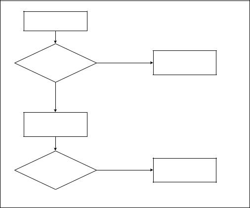
INSTRUCTION SET REFERENCE, A-M
These two methods are discussed in the following sections. For methods that are available in early processors, see Section: “Identification of Earlier IA-32 Processors” in Chapter 14 of the Intel® 64 and IA-32 Architectures Software Developer’s Manual, Volume 1.
The Processor Brand String Method
Figure 3-8 describes the algorithm used for detection of the brand string. Processor brand identification software should execute this algorithm on all Intel 64 and IA-32 processors.
This method (introduced with Pentium 4 processors) returns an ASCII brand identification string and the maximum operating frequency of the processor to the EAX, EBX, ECX, and EDX registers.
Input: EAX= |
|
|
|
0x80000000 |
|
|
|
CPUID |
|
|
|
IF (EAX & 0x80000000) |
False |
Processor Brand |
|
|
String Not |
||
|
|
|
Supported |
CPUID |
True ≥ |
|
|
Function |
|
|
|
Extended |
|
|
|
Supported |
|
|
|
|
|
|
|
EAX Return Value = |
|
|
|
Max. Extended CPUID |
|
|
|
Function Index |
|
|
|
IF (EAX Return Value |
True |
Processor Brand |
|
|
|||
≥ 0x80000004) |
|
String Supported |
|
|
|
|
OM15194 |
Figure 3-8. Determination of Support for the Processor Brand String
Vol. 2 3-181
INSTRUCTION SET REFERENCE, A-M
How Brand Strings Work
To use the brand string method, execute CPUID with EAX input of 8000002H through 80000004H. For each input value, CPUID returns 16 ASCII characters using EAX, EBX, ECX, and EDX. The returned string will be NULL-terminated.
Table 3-18 shows the brand string that is returned by the first processor in the Pentium 4 processor family.
Table 3-18. Processor Brand String Returned with Pentium 4 Processor
EAX Input Value |
Return Values |
|
ASCII Equivalent |
|
|
|
|
80000002H |
EAX = 20202020H |
“ |
” |
|
EBX = 20202020H |
“ |
” |
|
ECX = 20202020H |
“ |
” |
|
EDX = 6E492020H |
“nI ” |
|
|
|
|
|
80000003H |
EAX = 286C6574H |
“(let” |
|
|
EBX = 50202952H |
“P )R” |
|
|
ECX = 69746E65H |
“itne” |
|
|
EDX = 52286D75H |
“R(mu” |
|
|
|
|
|
80000004H |
EAX = 20342029H |
“ 4 )” |
|
|
EBX = 20555043H |
“ UPC” |
|
|
ECX = 30303531H |
“0051” |
|
|
EDX = 007A484DH |
“\0zHM” |
|
|
|
|
|
Extracting the Maximum Processor Frequency from Brand Strings
Figure 3-9 provides an algorithm which software can use to extract the maximum processor operating frequency from the processor brand string.
NOTE
When a frequency is given in a brand string, it is the maximum qualified frequency of the processor, not the frequency at which the processor is currently running.
3-182 Vol. 2

INSTRUCTION SET REFERENCE, A-M
6FDQ %UDQG 6WULQJ LQ |
|
|
|
|
|
5HYHUVH %\WH 2UGHU |
|
|
|
|
|
]+0 RU |
|
|
|
|
|
]+* RU |
0DWFK |
|
|
|
|
]+7 |
6XEVWULQJ |
|
|
|
|
|
|
)DOVH |
|
|
|
,) 6XEVWULQJ 0DWFKHG |
|
5HSRUW (UURU |
|
||
'HWHUPLQH )UHT |
7UXH |
,I ]+0 |
|
|
|
|
|
|
0XOWLSOLHU |
[ |
|
DQG 0XOWLSOLHU |
|
|
|
|
|
|
|
,I ]+* |
|
|
|
|
|
|
0XOWLSOLHU |
[ |
|
'HWHUPLQH 0XOWLSOLHU |
|
|
|
|
|
|
|
,I ]+7 |
|
|
|
|
|
|
0XOWLSOLHU |
[ |
|
|
|
6FDQ 'LJLWV |
|
|
|
|
|
8QWLO %ODQN |
|
|
|
|
|
|
5HYHUVH 'LJLWV |
|
|
'HWHUPLQH )UHT |
|
|
|
|
|
|
|
|
7R 'HFLPDO 9DOXH |
|
|
|
|
,Q 5HYHUVH 2UGHU |
|
|
|
0D[ 4XDOLILHG |
|
|
|
|
|
)UHTXHQF\ |
|
|
|
|
|
|
|
|
)UHT |
;< = LI |
|
)UHT [ 0XOWLSOLHU |
|
|
|
|
|
|
|
|
'LJLWV = <; |
|
|
|
|
|
|
|
20 |
Figure 3-9. Algorithm for Extracting Maximum Processor Frequency
The Processor Brand Index Method
The brand index method (introduced with Pentium® III Xeon® processors) provides an entry point into a brand identification table that is maintained in memory by system software and is accessible from systemand user-level code. In this table, each brand index is associate with an ASCII brand identification string that identifies the official Intel family and model number of a processor.
When CPUID executes with EAX set to 1, the processor returns a brand index to the low byte in EBX. Software can then use this index to locate the brand identification string for the processor in the brand identification table. The first entry (brand index 0) in this table is reserved, allowing for backward compatibility with processors that do not support the brand identification feature. Starting with processor signature
Vol. 2 3-183
INSTRUCTION SET REFERENCE, A-M
family ID = 0FH, model = 03H, brand index method is no longer supported. Use brand string method instead.
Table 3-19 shows brand indices that have identification strings associated with them.
|
Table 3-19. Mapping of Brand Indices; and |
|
Intel 64 and IA-32 Processor Brand Strings |
|
|
Brand Index |
Brand String |
|
|
00H |
This processor does not support the brand identification feature |
|
|
01H |
Intel(R) Celeron(R) processor1 |
02H |
Intel(R) Pentium(R) III processor1 |
03H |
Intel(R) Pentium(R) III Xeon(R) processor; If processor signature = |
|
000006B1h, then Intel(R) Celeron(R) processor |
|
|
04H |
Intel(R) Pentium(R) III processor |
|
|
06H |
Mobile Intel(R) Pentium(R) III processor-M |
|
|
07H |
Mobile Intel(R) Celeron(R) processor1 |
08H |
Intel(R) Pentium(R) 4 processor |
|
|
09H |
Intel(R) Pentium(R) 4 processor |
|
|
0AH |
Intel(R) Celeron(R) processor1 |
0BH |
Intel(R) Xeon(R) processor; If processor signature = 00000F13h, then Intel(R) |
|
Xeon(R) processor MP |
|
|
0CH |
Intel(R) Xeon(R) processor MP |
|
|
0EH |
Mobile Intel(R) Pentium(R) 4 processor-M; If processor signature = |
|
00000F13h, then Intel(R) Xeon(R) processor |
|
|
0FH |
Mobile Intel(R) Celeron(R) processor1 |
11H |
Mobile Genuine Intel(R) processor |
|
|
12H |
Intel(R) Celeron(R) M processor |
|
|
13H |
Mobile Intel(R) Celeron(R) processor1 |
14H |
Intel(R) Celeron(R) processor |
|
|
15H |
Mobile Genuine Intel(R) processor |
|
|
16H |
Intel(R) Pentium(R) M processor |
|
|
17H |
Mobile Intel(R) Celeron(R) processor1 |
18H – 0FFH |
RESERVED |
|
|
NOTES:
1. Indicates versions of these processors that were introduced after the Pentium III
3-184 Vol. 2
INSTRUCTION SET REFERENCE, A-M
IA-32 Architecture Compatibility
CPUID is not supported in early models of the Intel486 processor or in any IA-32 processor earlier than the Intel486 processor.
Operation
IA32_BIOS_SIGN_ID MSR ← Update with installed microcode revision number;
CASE (EAX) OF
EAX = 0:
EAX ← Highest basic function input value understood by CPUID; EBX ← Vendor identification string;
EDX ← Vendor identification string; ECX ← Vendor identification string;
BREAK;
EAX = 1H:
EAX[3:0] ← Stepping ID; EAX[7:4] ← Model; EAX[11:8] ← Family;
EAX[13:12] ← Processor type; EAX[15:14] ← Reserved; EAX[19:16] ← Extended Model; EAX[23:20] ← Extended Family;
EAX[31:24] ← Reserved;
EBX[7:0] ← Brand Index; (* Reserved if the value is zero. *) EBX[15:8] ← CLFLUSH Line Size;
EBX[16:23] ← Reserved; (* Number of threads enabled = 2 if MT enable fuse set. *) EBX[24:31] ← Initial APIC ID;
ECX ← Feature flags; (* See Figure 3-6. *)
EDX ← Feature flags; (* See Figure 3-7. *)
BREAK;
EAX = 2H:
EAX ← Cache and TLB information; EBX ← Cache and TLB information; ECX ← Cache and TLB information; EDX ← Cache and TLB information;
BREAK;
EAX = 3H:
EAX ← Reserved;
EBX ← Reserved;
ECX ← ProcessorSerialNumber[31:0];
(* Pentium III processors only, otherwise reserved. *)
EDX ← ProcessorSerialNumber[63:32];
(* Pentium III processors only, otherwise reserved. *
Vol. 2 3-185
INSTRUCTION SET REFERENCE, A-M
BREAK
EAX = 4H:
EAX ← Deterministic Cache Parameters Leaf; (* See Table 3-12. *)
EBX ← Deterministic Cache Parameters Leaf;
ECX ← Deterministic Cache Parameters Leaf;
EDX ← Deterministic Cache Parameters Leaf;
BREAK;
EAX = 5H:
EAX ← MONITOR/MWAIT Leaf; (* See Table 3-12. *)
EBX ← MONITOR/MWAIT Leaf;
ECX ← MONITOR/MWAIT Leaf;
EDX ← MONITOR/MWAIT Leaf;
BREAK;
EAX = 6H:
EAX ← Thermal and Power Management Leaf; (* See Table 3-12. *)
EBX ← Thermal and Power Management Leaf;
ECX ← Thermal and Power Management Leaf;
EDX ← Thermal and Power Management Leaf;
BREAK;
EAX = 7H or 8H or 9H:
EAX ← Reserved = 0;
EBX ← Reserved = 0;
ECX ← Reserved = 0;
EDX ← Reserved = 0;
BREAK;
EAX = AH:
EAX ← Architectural Performance Monitoring Leaf; (* See Table 3-12. *)
EBX ← Architectural Performance Monitoring Leaf;
ECX ← Architectural Performance Monitoring Leaf;
EDX ← Architectural Performance Monitoring Leaf;
BREAK;
EAX = 80000000H:
EAX ← Highest extended function input value understood by CPUID; EBX ← Reserved;
ECX ← Reserved;
EDX ← Reserved;
BREAK;
EAX = 80000001H:
EAX ← Reserved;
EBX ← Reserved;
ECX ← Extended Feature Bits (* See Table 3-12.*); EDX ← Extended Feature Bits (* See Table 3-12. *);
BREAK;
3-186 Vol. 2
INSTRUCTION SET REFERENCE, A-M
EAX = 80000002H:
EAX ← Processor Brand String;
EBX ← Processor Brand String, continued;
ECX ← Processor Brand String, continued;
EDX ← Processor Brand String, continued;
BREAK;
EAX = 80000003H:
EAX ← Processor Brand String, continued;
EBX ← Processor Brand String, continued;
ECX ← Processor Brand String, continued;
EDX ← Processor Brand String, continued;
BREAK;
EAX = 80000004H:
EAX ← Processor Brand String, continued;
EBX ← Processor Brand String, continued;
ECX ← Processor Brand String, continued;
EDX ← Processor Brand String, continued;
BREAK;
EAX = 80000005H:
EAX ← Reserved = 0;
EBX ← Reserved = 0;
ECX ← Reserved = 0;
EDX ← Reserved = 0;
BREAK;
EAX = 80000006H:
EAX ← Reserved = 0;
EBX ← Reserved = 0;
ECX ← Cache information;
EDX ← Reserved = 0;
BREAK;
EAX = 80000007H:
EAX ← Reserved = 0;
EBX ← Reserved = 0;
ECX ← Reserved = 0;
EDX ← Reserved = 0;
BREAK;
EAX = 80000008H:
EAX ← Reserved = 0;
EBX ← Reserved = 0;
ECX ← Reserved = 0;
EDX ← Reserved = 0;
BREAK;
DEFAULT: (* EAX = Value outside of recognized range for CPUID. *)
Vol. 2 3-187
INSTRUCTION SET REFERENCE, A-M
EAX ← Reserved; (* Information returned for highest basic information leaf. *) EBX ← Reserved; (* Information returned for highest basic information leaf. *) ECX ← Reserved; (* Information returned for highest basic information leaf. *) EDX ← Reserved; (* Information returned for highest basic information leaf. *)
BREAK;
ESAC;
Flags Affected
None.
Exceptions (All Operating Modes)
None.
NOTE
In earlier IA-32 processors that do not support the CPUID instruction, execution of the instruction results in an invalid opcode (#UD) exception being generated.
3-188 Vol. 2
INSTRUCTION SET REFERENCE, A-M
CVTDQ2PD—Convert Packed Doubleword Integers to Packed DoublePrecision Floating-Point Values
|
|
64-Bit |
Compat/ |
|
Opcode |
Instruction |
Mode |
Leg Mode |
Description |
F3 0F E6 |
CVTDQ2PD xmm1, |
Valid |
Valid |
Convert two packed signed |
|
xmm2/m64 |
|
|
doubleword integers from |
|
|
|
|
xmm2/m128 to two packed |
|
|
|
|
double-precision floating-point |
|
|
|
|
values in xmm1. |
|
|
|
|
|
Description
Converts two packed signed doubleword integers in the source operand (second operand) to two packed double-precision floating-point values in the destination operand (first operand).
The source operand can be an XMM register or a 64-bit memory location. The destination operand is an XMM register. When the source operand is an XMM register, the packed integers are located in the low quadword of the register.
In 64-bit mode, use of the REX.R prefix permits this instruction to access additional registers (XMM8-XMM15).
Operation
DEST[63:0] ← Convert_Integer_To_Double_Precision_Floating_Point(SRC[31:0]);
DEST[127:64] ← Convert_Integer_To_Double_Precision_Floating_Point(SRC[63:32]);
Intel C/C++ Compiler Intrinsic Equivalent
CVTDQ2PD __m128d _mm_cvtepi32_pd(__m128di a)
SIMD Floating-Point Exceptions
None.
Protected Mode Exceptions
#GP(0) |
For an illegal memory operand effective address in the CS, DS, |
|
ES, FS or GS segments. |
#SS(0) |
For an illegal address in the SS segment. |
#PF(fault-code) |
For a page fault. |
#NM |
If CR0.TS[bit 3] = 1. |
#UD |
If CR0.EM[bit 2] = 1. |
|
If CR4.OSFXSR[bit 9] = 0. |
|
If CPUID.01H:EDX.SSE2[bit 26] = 0. |
Vol. 2 3-189
INSTRUCTION SET REFERENCE, A-M
#AC(0) |
If alignment checking is enabled and an unaligned memory |
|
reference is made while the current privilege level is 3. |
Real-Address Mode Exceptions
GP(0) |
If any part of the operand lies outside the effective address |
|
space from 0 to FFFFH. |
#NM |
If CR0.TS[bit 3] = 1. |
#UD |
If CR0.EM[bit 2] = 1. |
|
If CR4.OSFXSR[bit 9] = 0. |
|
If CPUID.01H:EDX.SSE2[bit 26] = 0. |
Virtual-8086 Mode Exceptions
Same exceptions as in Real Address Mode
#PF(fault-code) |
For a page fault. |
#AC(0) |
If alignment checking is enabled and an unaligned memory |
|
reference is made. |
Compatibility Mode Exceptions
Same exceptions as in Protected Mode.
64-Bit Mode Exceptions
#SS(0) |
If a memory address referencing the SS segment is in a non- |
|
canonical form. |
#GP(0) |
If the memory address is in a non-canonical form. |
#PF(fault-code) |
For a page fault. |
#NM |
If CR0.TS[bit 3] = 1. |
#UD |
If CR0.EM[bit 2] = 1. |
|
If CR4.OSFXSR[bit 9] = 0. |
|
If CPUID.01H:EDX.SSE2[bit 26] = 0. |
#AC(0) |
If alignment checking is enabled and an unaligned memory |
|
reference is made while the current privilege level is 3. |
3-190 Vol. 2
INSTRUCTION SET REFERENCE, A-M
CVTDQ2PS—Convert Packed Doubleword Integers to Packed SinglePrecision Floating-Point Values
|
|
64-Bit |
Compat/ |
|
Opcode |
Instruction |
Mode |
Leg Mode |
Description |
0F 5B /r |
CVTDQ2PS xmm1, |
Valid |
Valid |
Convert four packed signed |
|
xmm2/m128 |
|
|
doubleword integers from |
|
|
|
|
xmm2/m128 to four |
|
|
|
|
packed single-precision |
|
|
|
|
floating-point values in |
|
|
|
|
xmm1. |
|
|
|
|
|
Description
Converts four packed signed doubleword integers in the source operand (second operand) to four packed single-precision floating-point values in the destination operand (first operand).
The source operand can be an XMM register or a 128-bit memory location. The destination operand is an XMM register. When a conversion is inexact, rounding is performed according to the rounding control bits in the MXCSR register.
In 64-bit mode, use of the REX.R prefix permits this instruction to access additional registers (XMM8-XMM15).
Operation
DEST[31:0] ← Convert_Integer_To_Single_Precision_Floating_Point(SRC[31:0]);
DEST[63:32] ← Convert_Integer_To_Single_Precision_Floating_Point(SRC[63:32]);
DEST[95:64] ← Convert_Integer_To_Single_Precision_Floating_Point(SRC[95:64]);
DEST[127:96] ← Convert_Integer_To_Single_Precision_Floating_Point(SRC[127:96]);
Intel C/C++ Compiler Intrinsic Equivalent
CVTDQ2PS __m128d _mm_cvtepi32_ps(__m128di a)
SIMD Floating-Point Exceptions
Precision.
Protected Mode Exceptions
#GP(0) |
For an illegal memory operand effective address in the CS, DS, |
|
ES, FS or GS segments. |
|
If a memory operand is not aligned on a 16-byte boundary, |
|
regardless of segment. |
#SS(0) |
For an illegal address in the SS segment. |
Vol. 2 3-191
INSTRUCTION SET REFERENCE, A-M
#PF(fault-code) |
For a page fault. |
#NM |
If CR0.TS[bit 3] = 1. |
#XM |
If an unmasked SIMD floating-point exception and CR4.OSXM- |
|
MEXCPT[bit 10] = 1. |
#UD |
If an unmasked SIMD floating-point exception and CR4.OSXM- |
|
MEXCPT[bit 10] = 0. |
|
If CR0.EM[bit 2] = 1. |
|
If CR4.OSFXSR[bit 9] = 0. |
|
If CPUID.01H:EDX.SSE2[bit 26] = 0. |
Real-Address Mode Exceptions
#GP(0) |
If a memory operand is not aligned on a 16-byte boundary, |
|
regardless of segment. |
|
If any part of the operand lies outside the effective address |
|
space from 0 to FFFFH. |
#NM |
If CR0.TS[bit 3] = 1. |
#XM |
If an unmasked SIMD floating-point exception and CR4.OSXM- |
|
MEXCPT[bit 10] = 1. |
#UD |
If an unmasked SIMD floating-point exception and CR4.OSXM- |
|
MEXCPT[bit 10] = 0. |
|
If CR0.EM[bit 2] = 1. |
|
If CR4.OSFXSR[bit 9] = 0. |
|
If CPUID.01H:EDX.SSE2[bit 26] = 0. |
Virtual-8086 Mode Exceptions
Same exceptions as in Real Address Mode #PF(fault-code) For a page fault.
Compatibility Mode Exceptions
Same exceptions as in Protected Mode.
3-192 Vol. 2
|
INSTRUCTION SET REFERENCE, A-M |
64-Bit Mode Exceptions |
|
#SS(0) |
If a memory address referencing the SS segment is in a non- |
|
canonical form. |
#GP(0) |
If the memory address is in a non-canonical form. |
|
If memory operand is not aligned on a 16-byte boundary, |
|
regardless of segment. |
#PF(fault-code) |
For a page fault. |
#NM |
If CR0.TS[bit 3] = 1. |
#XM |
If an unmasked SIMD floating-point exception and CR4.OSXM- |
|
MEXCPT[bit 10] = 1. |
#UD |
If an unmasked SIMD floating-point exception and CR4.OSXM- |
|
MEXCPT[bit 10] = 0. |
If CR0.EM[bit 2] = 1.
If CR4.OSFXSR[bit 9] = 0.
If CPUID.01H:EDX.SSE2[bit 26] = 0.
Vol. 2 3-193
INSTRUCTION SET REFERENCE, A-M
CVTPD2DQ—Convert Packed Double-Precision Floating-Point Values to Packed Doubleword Integers
|
|
64-Bit |
Compat/ |
|
Opcode |
Instruction |
Mode |
Leg Mode |
Description |
F2 0F E6 |
CVTPD2DQ xmm1, |
Valid |
Valid |
Convert two packed double- |
|
xmm2/m128 |
|
|
precision floating-point values |
|
|
|
|
from xmm2/m128 to two |
|
|
|
|
packed signed doubleword |
|
|
|
|
integers in xmm1. |
|
|
|
|
|
Description
Converts two packed double-precision floating-point values in the source operand (second operand) to two packed signed doubleword integers in the destination operand (first operand).
The source operand can be an XMM register or a 128-bit memory location. The destination operand is an XMM register. The result is stored in the low quadword of the destination operand and the high quadword is cleared to all 0s.
When a conversion is inexact, the value returned is rounded according to the rounding control bits in the MXCSR register. If a converted result is larger than the maximum signed doubleword integer, the floating-point invalid exception is raised, and if this exception is masked, the indefinite integer value (80000000H) is returned.
In 64-bit mode, use of the REX.R prefix permits this instruction to access additional registers (XMM8-XMM15).
Operation
DEST[31:0] ← Convert_Double_Precision_Floating_Point_To_Integer(SRC[63:0]);
DEST[63:32] ← Convert_Double_Precision_Floating_Point_To_Integer(SRC[127:64]);
DEST[127:64] ← 0000000000000000H;
Intel C/C++ Compiler Intrinsic Equivalent
CVTPD2DQ __m128d _mm_cvtpd_epi32(__m128d a)
SIMD Floating-Point Exceptions
Invalid, Precision.
Protected Mode Exceptions
#GP(0) |
For an illegal memory operand effective address in the CS, DS, |
|
ES, FS or GS segments.segments. |
|
If a memory operand is not aligned on a 16-byte boundary, |
|
regardless of segment. |
3-194 Vol. 2
|
INSTRUCTION SET REFERENCE, A-M |
#SS(0) |
For an illegal address in the SS segment. |
#PF(fault-code) |
For a page fault. |
#NM |
If CR0.TS[bit 3] = 1. |
#XM |
If an unmasked SIMD floating-point exception and CR4.OSXM- |
|
MEXCPT[bit 10] = 1. |
#UD |
If an unmasked SIMD floating-point exception and CR4.OSXM- |
|
MEXCPT[bit 10] = 0. |
|
If CR0.EM[bit 2] = 1. |
|
If CR4.OSFXSR[bit 9] = 0. |
|
If CPUID.01H:EDX.SSE2[bit 26] = 0. |
Real-Address Mode Exceptions |
|
#GP(0) |
If a memory operand is not aligned on a 16-byte boundary, |
|
regardless of segment. |
|
If any part of the operand lies outside the effective address |
|
space from 0 to FFFFH. |
#NM |
If CR0.TS[bit 3] = 1. |
#XM |
If an unmasked SIMD floating-point exception and CR4.OSXM- |
|
MEXCPT[bit 10] = 1. |
#UD |
If an unmasked SIMD floating-point exception and CR4.OSXM- |
|
MEXCPT[bit 10] = 0. |
If CR0.EM[bit 2] = 1.
If CR4.OSFXSR[bit 9] = 0.
If CPUID.01H:EDX.SSE2[bit 26] = 0.
Virtual-8086 Mode Exceptions
Same exceptions as in Real Address Mode #PF(fault-code) For a page fault.
Compatibility Mode Exceptions
Same exceptions as in Protected Mode.
64-Bit Mode Exceptions
#SS(0) |
If a memory address referencing the SS segment is in a non- |
|
canonical form. |
#GP(0) |
If the memory address is in a non-canonical form. |
|
If memory operand is not aligned on a 16-byte boundary, |
|
regardless of segment. |
#PF(fault-code) |
For a page fault. |
Vol. 2 3-195
INSTRUCTION SET REFERENCE, A-M
#NM |
If CR0.TS[bit 3] = 1. |
#XM |
If an unmasked SIMD floating-point exception and CR4.OSXM- |
|
MEXCPT[bit 10] = 1. |
#UD |
If an unmasked SIMD floating-point exception and CR4.OSXM- |
|
MEXCPT[bit 10] = 0. |
|
If CR0.EM[bit 2] = 1. |
|
If CR4.OSFXSR[bit 9] = 0. |
|
If CPUID.01H:EDX.SSE2[bit 26] = 0. |
3-196 Vol. 2
INSTRUCTION SET REFERENCE, A-M
CVTPD2PI—Convert Packed Double-Precision Floating-Point Values to Packed Doubleword Integers
|
|
|
Compat/ |
|
Opcode |
Instruction |
64-Bit Mode |
Leg Mode |
Description |
66 0F 2D |
CVTPD2PI mm, |
Valid |
Valid |
Convert two packed double- |
/r |
xmm/m128 |
|
|
precision floating-point |
|
|
|
|
values from xmm/m128 to |
|
|
|
|
two packed signed |
|
|
|
|
doubleword integers in mm. |
|
|
|
|
|
Description
Converts two packed double-precision floating-point values in the source operand (second operand) to two packed signed doubleword integers in the destination operand (first operand).
The source operand can be an XMM register or a 128-bit memory location. The destination operand is an MMX technology register.
When a conversion is inexact, the value returned is rounded according to the rounding control bits in the MXCSR register. If a converted result is larger than the maximum signed doubleword integer, the floating-point invalid exception is raised, and if this exception is masked, the indefinite integer value (80000000H) is returned.
This instruction causes a transition from x87 FPU to MMX technology operation (that is, the x87 FPU top-of-stack pointer is set to 0 and the x87 FPU tag word is set to all 0s [valid]). If this instruction is executed while an x87 FPU floating-point exception is pending, the exception is handled before the CVTPD2PI instruction is executed.
In 64-bit mode, use of the REX.R prefix permits this instruction to access additional registers (XMM8-XMM15).
Operation
DEST[31:0] ← Convert_Double_Precision_Floating_Point_To_Integer(SRC[63:0]);
DEST[63:32] ← Convert_Double_Precision_Floating_Point_To_Integer(SRC[127:64]);
Intel C/C++ Compiler Intrinsic Equivalent
CVTPD1PI |
__m64 _mm_cvtpd_pi32(__m128d a) |
SIMD Floating-Point Exceptions
Invalid, Precision.
Vol. 2 3-197
INSTRUCTION SET REFERENCE, A-M
Protected Mode Exceptions
#GP(0) |
For an illegal memory operand effective address in the CS, DS, |
|
ES, FS or GS segments. |
|
If a memory operand is not aligned on a 16-byte boundary, |
|
regardless of segment. |
#SS(0) |
For an illegal address in the SS segment. |
#PF(fault-code) |
For a page fault. |
#MF |
If there is a pending x87 FPU exception. |
#NM |
If CR0.TS[bit 3] = 1. |
#XM |
If an unmasked SIMD floating-point exception and CR4.OSXM- |
|
MEXCPT[bit 10] = 1. |
#UD |
If an unmasked SIMD floating-point exception and CR4.OSXM- |
|
MEXCPT[bit 10] = 0. |
|
If CR0.EM[bit 2] = 1. |
|
If CR4.OSFXSR[bit 9] = 0. |
|
If CPUID.01H:EDX.SSE2[bit 26] = 0. |
Real-Address Mode Exceptions
#GP(0) |
If a memory operand is not aligned on a 16-byte boundary, |
|
regardless of segment. |
|
If any part of the operand lies outside the effective address |
|
space from 0 to FFFFH. |
#NM |
If CR0.TS[bit 3] = 1. |
#MF |
If there is a pending x87 FPU exception. |
#XM |
If an unmasked SIMD floating-point exception and CR4.OSXM- |
|
MEXCPT[bit 10] = 1. |
#UD |
If an unmasked SIMD floating-point exception and CR4.OSXM- |
|
MEXCPT[bit 10] = 0. |
|
If CR0.EM[bit 2] = 1. |
|
If CR4.OSFXSR[bit 9] = 0. |
|
If CPUID.01H:EDX.SSE2[bit 26] = 0. |
Virtual-8086 Mode Exceptions
Same exceptions as in Real Address Mode #PF(fault-code) For a page fault.
Compatibility Mode Exceptions
Same exceptions as in Protected Mode.
3-198 Vol. 2
|
INSTRUCTION SET REFERENCE, A-M |
64-Bit Mode Exceptions |
|
#SS(0) |
If a memory address referencing the SS segment is in a non- |
|
canonical form. |
#GP(0) |
If the memory address is in a non-canonical form. |
|
If memory operand is not aligned on a 16-byte boundary, |
|
regardless of segment. |
#PF(fault-code) |
For a page fault. |
#MF |
If there is a pending x87 FPU exception. |
#NM |
If CR0.TS[bit 3] = 1. |
#XM |
If an unmasked SIMD floating-point exception and CR4.OSXM- |
|
MEXCPT[bit 10] = 1. |
#UD |
If an unmasked SIMD floating-point exception and CR4.OSXM- |
MEXCPT[bit 10] = 0.
If CR0.EM[bit 2] = 1.
If CR4.OSFXSR[bit 9] = 0.
If CPUID.01H:EDX.SSE2[bit 26] = 0.
Vol. 2 3-199
INSTRUCTION SET REFERENCE, A-M
CVTPD2PS—Convert Packed Double-Precision Floating-Point Values to Packed Single-Precision Floating-Point Values
|
|
64-Bit |
Compat/ |
|
Opcode |
Instruction |
Mode |
Leg Mode |
Description |
66 0F 5A |
CVTPD2PS xmm1, |
Valid |
Valid |
Convert two packed double- |
/r |
xmm2/m128 |
|
|
precision floating-point values in |
|
|
|
|
xmm2/m128 to two packed |
|
|
|
|
single-precision floating-point |
|
|
|
|
values in xmm1. |
|
|
|
|
|
Description
Converts two packed double-precision floating-point values in the source operand (second operand) to two packed single-precision floating-point values in the destination operand (first operand).
The source operand can be an XMM register or a 128-bit memory location. The destination operand is an XMM register. The result is stored in the low quadword of the destination operand, and the high quadword is cleared to all 0s. When a conversion is inexact, the value returned is rounded according to the rounding control bits in the MXCSR register.
In 64-bit mode, use of the REX.R prefix permits this instruction to access additional registers (XMM8-XMM15).
Operation
DEST[31:0] ← Convert_Double_Precision_To_Single_Precision_Floating_Point(SRC[63:0]);
DEST[63:32] ← Convert_Double_Precision_To_Single_Precision_
Floating_Point(SRC[127:64]);
DEST[127:64] ← 0000000000000000H;
Intel C/C++ Compiler Intrinsic Equivalent
CVTPD2PS __m128d _mm_cvtpd_ps(__m128d a)
SIMD Floating-Point Exceptions
Overflow, Underflow, Invalid, Precision, Denormal.
Protected Mode Exceptions
#GP(0) |
For an illegal memory operand effective address in the CS, DS, |
|
ES, FS or GS segments. |
|
If a memory operand is not aligned on a 16-byte boundary, |
|
regardless of segment. |
#SS(0) |
For an illegal address in the SS segment. |
3-200 Vol. 2
|
INSTRUCTION SET REFERENCE, A-M |
#PF(fault-code) |
For a page fault. |
#NM |
If CR0.TS[bit 3] = 1. |
#XM |
If an unmasked SIMD floating-point exception and CR4.OSXM- |
|
MEXCPT[bit 10] = 1. |
#UD |
If an unmasked SIMD floating-point exception and CR4.OSXM- |
|
MEXCPT[bit 10] = 0. |
|
If CR0.EM[bit 2] = 1. |
|
If CR4.OSFXSR[bit 9] = 0. |
|
If CPUID.01H:EDX.SSE2[bit 26] = 0. |
Real-Address Mode Exceptions |
|
#GP(0) |
If a memory operand is not aligned on a 16-byte boundary, |
|
regardless of segment. |
|
If any part of the operand lies outside the effective address |
|
space from 0 to FFFFH. |
#NM |
If CR0.TS[bit 3] = 1. |
#XM |
If an unmasked SIMD floating-point exception and CR4.OSXM- |
|
MEXCPT[bit 10] = 1. |
#UD |
If an unmasked SIMD floating-point exception and CR4.OSXM- |
MEXCPT[bit 10] = 0.
If CR0.EM[bit 2] = 1.
If CR4.OSFXSR[bit 9] = 0.
If CPUID.01H:EDX.SSE2[bit 26] = 0.
Virtual-8086 Mode Exceptions
Same exceptions as in Real Address Mode #PF(fault-code) For a page fault.
Compatibility Mode Exceptions
Same exceptions as in Protected Mode.
Vol. 2 3-201
INSTRUCTION SET REFERENCE, A-M
64-Bit Mode Exceptions
#SS(0) |
If a memory address referencing the SS segment is in a non- |
|
canonical form. |
#GP(0) |
If the memory address is in a non-canonical form. |
|
If memory operand is not aligned on a 16-byte boundary, |
|
regardless of segment. |
#PF(fault-code) |
For a page fault. |
#NM |
If CR0.TS[bit 3] = 1. |
#XM |
If an unmasked SIMD floating-point exception and CR4.OSXM- |
|
MEXCPT[bit 10] = 1. |
#UD |
If an unmasked SIMD floating-point exception and CR4.OSXM- |
|
MEXCPT[bit 10] = 0. |
|
If CR0.EM[bit 2] = 1. |
|
If CR4.OSFXSR[bit 9] = 0. |
|
If CPUID.01H:EDX.SSE2[bit 26] = 0. |
3-202 Vol. 2

INSTRUCTION SET REFERENCE, A-M
CVTPI2PD—Convert Packed Doubleword Integers to Packed DoublePrecision Floating-Point Values
|
|
64-Bit |
Compat/ |
|
Opcode |
Instruction |
Mode |
Leg Mode |
Description |
66 0F 2A /r |
CVTPI2PD |
Valid |
Valid |
Convert two packed signed |
|
xmm, |
|
|
doubleword integers from |
|
mm/m64* |
|
|
mm/mem64 to two packed double- |
|
|
|
|
precision floating-point values in |
|
|
|
|
xmm. |
NOTES:
* Operation is different for different operand sets; see the Description section.
Description
Converts two packed signed doubleword integers in the source operand (second operand) to two packed double-precision floating-point values in the destination operand (first operand).
The source operand can be an MMX technology register or a 64-bit memory location. The destination operand is an XMM register. In addition, depending on the operand configuration:
•For operands xmm, mm: the instruction causes a transition from x87 FPU to MMX technology operation (that is, the x87 FPU top-of-stack pointer is set to 0 and the x87 FPU tag word is set to all 0s [valid]). If this instruction is executed while an x87 FPU floating-point exception is pending, the exception is handled before the CVTPI2PD instruction is executed.
•For operands xmm, m64: the instruction does not cause a transition to MMX technology and does not take x87 FPU exceptions.
In 64-bit mode, use of the REX.R prefix permits this instruction to access additional registers (XMM8-XMM15).
Operation
DEST[63:0] ← Convert_Integer_To_Double_Precision_Floating_Point(SRC[31:0]);
DEST[127:64] ← Convert_Integer_To_Double_Precision_Floating_Point(SRC[63:32]);
Intel C/C++ Compiler Intrinsic Equivalent
CVTPI2PD __m128d _mm_cvtpi32_pd(__m64 a)
SIMD Floating-Point Exceptions
None.
Vol. 2 3-203
INSTRUCTION SET REFERENCE, A-M
Protected Mode Exceptions
#GP(0) |
For an illegal memory operand effective address in the CS, DS, |
|
ES, FS or GS segments. |
#SS(0) |
For an illegal address in the SS segment. |
#PF(fault-code) |
For a page fault. |
#NM |
If CR0.TS[bit 3] = 1. |
#MF |
If there is a pending x87 FPU exception. |
#UD |
If CR0.EM[bit 2] = 1. |
|
If CR4.OSFXSR[bit 9] = 0. |
|
If CPUID.01H:EDX.SSE2[bit 26] = 0. |
#AC(0) |
If alignment checking is enabled and an unaligned memory |
|
reference is made while the current privilege level is 3. |
Real-Address Mode Exceptions
GP(0) |
If any part of the operand lies outside the effective address |
|
space from 0 to FFFFH. |
#NM |
If CR0.TS[bit 3] = 1. |
#MF |
If there is a pending x87 FPU exception. |
#UD |
If CR0.EM[bit 2] = 1. |
|
If CR4.OSFXSR[bit 9] = 0. |
|
If CPUID.01H:EDX.SSE2[bit 26] = 0. |
Virtual-8086 Mode Exceptions
Same exceptions as in Real Address Mode
#PF(fault-code) |
For a page fault. |
#AC(0) |
If alignment checking is enabled and an unaligned memory |
|
reference is made. |
Compatibility Mode Exceptions
Same exceptions as in Protected Mode.
3-204 Vol. 2
|
INSTRUCTION SET REFERENCE, A-M |
64-Bit Mode Exceptions |
|
#SS(0) |
If a memory address referencing the SS segment is in a non- |
|
canonical form. |
#GP(0) |
If the memory address is in a non-canonical form. |
#PF(fault-code) |
For a page fault. |
#NM |
If CR0.TS[bit 3] = 1. |
#MF |
If there is a pending x87 FPU exception. |
#UD |
If CR0.EM[bit 2] = 1. |
|
If CR4.OSFXSR[bit 9] = 0. |
|
If CPUID.01H:EDX.SSE2[bit 26] = 0. |
#AC(0) |
If alignment checking is enabled and an unaligned memory |
|
reference is made while the current privilege level is 3. |
Vol. 2 3-205
INSTRUCTION SET REFERENCE, A-M
CVTPI2PS—Convert Packed Doubleword Integers to Packed SinglePrecision Floating-Point Values
|
|
64-Bit |
Compat/ |
|
Opcode |
Instruction |
Mode |
Leg Mode |
Description |
0F 2A /r |
CVTPI2PS xmm, |
Valid |
Valid |
Convert two signed doubleword |
|
mm/m64 |
|
|
integers from mm/m64 to two |
|
|
|
|
single-precision floating-point values |
|
|
|
|
in xmm. |
|
|
|
|
|
Description
Converts two packed signed doubleword integers in the source operand (second operand) to two packed single-precision floating-point values in the destination operand (first operand).
The source operand can be an MMX technology register or a 64-bit memory location. The destination operand is an XMM register. The results are stored in the low quadword of the destination operand, and the high quadword remains unchanged. When a conversion is inexact, the value returned is rounded according to the rounding control bits in the MXCSR register.
This instruction causes a transition from x87 FPU to MMX technology operation (that is, the x87 FPU top-of-stack pointer is set to 0 and the x87 FPU tag word is set to all 0s [valid]). If this instruction is executed while an x87 FPU floating-point exception is pending, the exception is handled before the CVTPI2PS instruction is executed.
In 64-bit mode, use of the REX.R prefix permits this instruction to access additional registers (XMM8-XMM15).
Operation
DEST[31:0] ← Convert_Integer_To_Single_Precision_Floating_Point(SRC[31:0]); DEST[63:32] ← Convert_Integer_To_Single_Precision_Floating_Point(SRC[63:32]); (* High quadword of destination unchanged *)
Intel C/C++ Compiler Intrinsic Equivalent
CVTPI2PS __m128 _mm_cvtpi32_ps(__m128 a, __m64 b)
SIMD Floating-Point Exceptions
Precision.
Protected Mode Exceptions
#GP(0) |
For an illegal memory operand effective address in the CS, DS, |
|
ES, FS or GS segments. |
3-206 Vol. 2
|
INSTRUCTION SET REFERENCE, A-M |
#SS(0) |
For an illegal address in the SS segment. |
#PF(fault-code) |
For a page fault. |
#NM |
If CR0.TS[bit 3] = 1. |
#MF |
If there is a pending x87 FPU exception. |
#XM |
If an unmasked SIMD floating-point exception and CR4.OSXM- |
|
MEXCPT[bit 10] = 1. |
#UD |
If an unmasked SIMD floating-point exception and CR4.OSXM- |
|
MEXCPT[bit 10] = 0. |
|
If CR0.EM[bit 2] = 1. |
|
If CR4.OSFXSR[bit 9] = 0. |
|
If CPUID.01H:EDX.SSE[bit 25] = 0. |
#AC(0) |
If alignment checking is enabled and an unaligned memory |
|
reference is made while the current privilege level is 3. |
Real-Address Mode Exceptions |
|
GP(0) |
If any part of the operand lies outside the effective address |
|
space from 0 to FFFFH. |
#NM |
If CR0.TS[bit 3] = 1. |
#MF |
If there is a pending x87 FPU exception. |
#XM |
If an unmasked SIMD floating-point exception and CR4.OSXM- |
|
MEXCPT[bit 10] = 1. |
#UD |
If an unmasked SIMD floating-point exception and CR4.OSXM- |
MEXCPT[bit 10] = 0.
If CR0.EM[bit 2] = 1.
If CR4.OSFXSR[bit 9] = 0.
If CPUID.01H:EDX.SSE[bit 25] = 0.
Virtual-8086 Mode Exceptions
Same exceptions as in Real Address Mode
#PF(fault-code) |
For a page fault. |
#AC(0) |
If alignment checking is enabled and an unaligned memory |
|
reference is made. |
Compatibility Mode Exceptions
Same exceptions as in Protected Mode.
64-Bit Mode Exceptions
#SS(0) |
If a memory address referencing the SS segment is in a non- |
|
canonical form. |
Vol. 2 3-207
INSTRUCTION SET REFERENCE, A-M
#GP(0) |
If the memory address is in a non-canonical form. |
#PF(fault-code) |
For a page fault. |
#NM |
If CR0.TS[bit 3] = 1. |
#MF |
If there is a pending x87 FPU exception. |
#XM |
If an unmasked SIMD floating-point exception and CR4.OSXM- |
|
MEXCPT[bit 10] = 1. |
#UD |
If an unmasked SIMD floating-point exception and CR4.OSXM- |
|
MEXCPT[bit 10] = 0. |
|
If CR0.EM[bit 2] = 1. |
|
If CR4.OSFXSR[bit 9] = 0. |
|
If CPUID.01H:EDX.SSE[bit 25] = 0. |
#AC(0) |
If alignment checking is enabled and an unaligned memory |
|
reference is made while the current privilege level is 3. |
3-208 Vol. 2
INSTRUCTION SET REFERENCE, A-M
CVTPS2DQ—Convert Packed Single-Precision Floating-Point Values to Packed Doubleword Integers
|
|
64-Bit |
Compat/ |
|
Opcode |
Instruction |
Mode |
Leg Mode |
Description |
66 0F 5B |
CVTPS2DQ xmm1, |
Valid |
Valid |
Convert four packed single- |
/r |
xmm2/m128 |
|
|
precision floating-point values |
|
|
|
|
from xmm2/m128 to four packed |
|
|
|
|
signed doubleword integers in |
|
|
|
|
xmm1. |
|
|
|
|
|
Description
Converts four packed single-precision floating-point values in the source operand (second operand) to four packed signed doubleword integers in the destination operand (first operand).
The source operand can be an XMM register or a 128-bit memory location. The destination operand is an XMM register.
When a conversion is inexact, the value returned is rounded according to the rounding control bits in the MXCSR register. If a converted result is larger than the maximum signed doubleword integer, the floating-point invalid exception is raised, and if this exception is masked, the indefinite integer value (80000000H) is returned.
In 64-bit mode, use of the REX.R prefix permits this instruction to access additional registers (XMM8-XMM15).
Operation
DEST[31:0] ← Convert_Single_Precision_Floating_Point_To_Integer(SRC[31:0]);
DEST[63:32] ← Convert_Single_Precision_Floating_Point_To_Integer(SRC[63:32]);
DEST[95:64] ← Convert_Single_Precision_Floating_Point_To_Integer(SRC[95:64]);
DEST[127:96] ← Convert_Single_Precision_Floating_Point_To_Integer(SRC[127:96]);
Intel C/C++ Compiler Intrinsic Equivalent
CVTPS2DQ __m128d _mm_cvtps_epi32(__m128d a)
SIMD Floating-Point Exceptions
Invalid, Precision.
Vol. 2 3-209
INSTRUCTION SET REFERENCE, A-M
Protected Mode Exceptions
#GP(0) |
For an illegal memory operand effective address in the CS, DS, |
|
ES, FS or GS segments. |
|
If a memory operand is not aligned on a 16-byte boundary, |
|
regardless of segment. |
#SS(0) |
For an illegal address in the SS segment. |
#PF(fault-code) |
For a page fault. |
#NM |
If CR0.TS[bit 3] = 1. |
#XM |
If an unmasked SIMD floating-point exception and CR4.OSXM- |
|
MEXCPT[bit 10] = 1. |
#UD |
If an unmasked SIMD floating-point exception and CR4.OSXM- |
|
MEXCPT[bit 10] = 0. |
|
If CR0.EM[bit 2] = 1. |
|
If CR4.OSFXSR[bit 9] = 0. |
|
If CPUID.01H:EDX.SSE2[bit 26] = 0. |
Real-Address Mode Exceptions
#GP(0) |
If a memory operand is not aligned on a 16-byte boundary, |
|
regardless of segment. |
|
If any part of the operand lies outside the effective address |
|
space from 0 to FFFFH. |
#NM |
If CR0.TS[bit 3] = 1. |
#XM |
If an unmasked SIMD floating-point exception and CR4.OSXM- |
|
MEXCPT[bit 10] = 1. |
#UD |
If an unmasked SIMD floating-point exception and CR4.OSXM- |
|
MEXCPT[bit 10] = 0. |
|
If CR0.EM[bit 2] = 1. |
|
If CR4.OSFXSR[bit 9] = 0. |
|
If CPUID.01H:EDX.SSE2[bit 26] = 0. |
Virtual-8086 Mode Exceptions
Same exceptions as in Real Address Mode #PF(fault-code) For a page fault.
Compatibility Mode Exceptions
Same exceptions as in Protected Mode.
3-210 Vol. 2
|
INSTRUCTION SET REFERENCE, A-M |
64-Bit Mode Exceptions |
|
#SS(0) |
If a memory address referencing the SS segment is in a non- |
|
canonical form. |
#GP(0) |
If the memory address is in a non-canonical form. |
|
If memory operand is not aligned on a 16-byte boundary, |
|
regardless of segment. |
#PF(fault-code) |
For a page fault. |
#NM |
If CR0.TS[bit 3] = 1. |
#XM |
If an unmasked SIMD floating-point exception and CR4.OSXM- |
|
MEXCPT[bit 10] = 1. |
#UD |
If an unmasked SIMD floating-point exception and CR4.OSXM- |
|
MEXCPT[bit 10] = 0. |
If CR0.EM[bit 2] = 1.
If CR4.OSFXSR[bit 9] = 0.
If CPUID.01H:EDX.SSE2[bit 26] = 0.
Vol. 2 3-211
INSTRUCTION SET REFERENCE, A-M
CVTPS2PD—Convert Packed Single-Precision Floating-Point Values to Packed Double-Precision Floating-Point Values
|
|
64-Bit |
Compat/ |
|
Opcode |
Instruction |
Mode |
Leg Mode |
Description |
0F 5A /r |
CVTPS2PD xmm1, |
Valid |
Valid |
Convert two packed single-precision |
|
xmm2/m64 |
|
|
floating-point values in xmm2/m64 |
|
|
|
|
to two packed double-precision |
|
|
|
|
floating-point values in xmm1. |
|
|
|
|
|
Description
Converts two packed single-precision floating-point values in the source operand (second operand) to two packed double-precision floating-point values in the destination operand (first operand).
The source operand can be an XMM register or a 64-bit memory location. The destination operand is an XMM register. When the source operand is an XMM register, the packed single-precision floating-point values are contained in the low quadword of the register.
In 64-bit mode, use of the REX.R prefix permits this instruction to access additional registers (XMM8-XMM15).
Operation
DEST[63:0] ← Convert_Single_Precision_To_Double_Precision_Floating_Point(SRC[31:0]);
DEST[127:64] ← Convert_Single_Precision_To_Double_Precision_Floating_Point(SRC[63:32]);
Intel C/C++ Compiler Intrinsic Equivalent
CVTPS2PD __m128d _mm_cvtps_pd(__m128 a)
SIMD Floating-Point Exceptions
Invalid, Denormal.
Protected Mode Exceptions
#GP(0) |
For an illegal memory operand effective address in the CS, DS, |
|
ES, FS or GS segments. |
#SS(0) |
For an illegal address in the SS segment. |
#PF(fault-code) |
For a page fault. |
#NM |
If CR0.TS[bit 3] = 1. |
#XM |
If an unmasked SIMD floating-point exception and CR4.OSXM- |
|
MEXCPT[bit 10] = 1. |
3-212 Vol. 2
|
INSTRUCTION SET REFERENCE, A-M |
#UD |
If an unmasked SIMD floating-point exception and CR4.OSXM- |
|
MEXCPT[bit 10] = 0. |
|
If CR0.EM[bit 2] = 1. |
|
If CR4.OSFXSR[bit 9] = 0. |
|
If CPUID.01H:EDX.SSE2[bit 26] = 0. |
#AC(0) |
If alignment checking is enabled and an unaligned memory |
|
reference is made while the current privilege level is 3. |
Real-Address Mode Exceptions |
|
GP(0) |
If any part of the operand lies outside the effective address |
|
space from 0 to FFFFH. |
#NM |
If CR0.TS[bit 3] = 1. |
#XM |
If an unmasked SIMD floating-point exception and CR4.OSXM- |
|
MEXCPT[bit 10] = 1. |
#UD |
If an unmasked SIMD floating-point exception and CR4.OSXM- |
MEXCPT[bit 10] = 0.
If CR0.EM[bit 2] = 1.
If CR4.OSFXSR[bit 9] = 0.
If CPUID.01H:EDX.SSE2[bit 26] = 0.
Virtual-8086 Mode Exceptions
Same exceptions as in Real Address Mode
#PF(fault-code) |
For a page fault. |
#AC(0) |
If alignment checking is enabled and an unaligned memory |
|
reference is made. |
Compatibility Mode Exceptions
Same exceptions as in Protected Mode.
64-Bit Mode Exceptions
#SS(0) |
If a memory address referencing the SS segment is in a non- |
|
canonical form. |
#GP(0) |
If the memory address is in a non-canonical form. |
#PF(fault-code) |
For a page fault. |
#NM |
If CR0.TS[bit 3] = 1. |
#XM |
If an unmasked SIMD floating-point exception and CR4.OSXM- |
|
MEXCPT[bit 10] = 1. |
Vol. 2 3-213
INSTRUCTION SET REFERENCE, A-M
#UD |
If an unmasked SIMD floating-point exception and CR4.OSXM- |
|
MEXCPT[bit 10] = 0. |
|
If CR0.EM[bit 2] = 1. |
|
If CR4.OSFXSR[bit 9] = 0. |
|
If CPUID.01H:EDX.SSE2[bit 26] = 0. |
#AC(0) |
If alignment checking is enabled and an unaligned memory |
|
reference is made while the current privilege level is 3. |
3-214 Vol. 2
INSTRUCTION SET REFERENCE, A-M
CVTPS2PI—Convert Packed Single-Precision Floating-Point Values to Packed Doubleword Integers
|
|
64-Bit |
Compat/ |
|
Opcode |
Instruction |
Mode |
Leg Mode |
Description |
0F 2D /r |
CVTPS2PI mm, |
Valid |
Valid |
Convert two packed single-precision |
|
xmm/m64 |
|
|
floating-point values from xmm/m64 to |
|
|
|
|
two packed signed doubleword integers |
|
|
|
|
in mm. |
|
|
|
|
|
Description
Converts two packed single-precision floating-point values in the source operand (second operand) to two packed signed doubleword integers in the destination operand (first operand).
The source operand can be an XMM register or a 128-bit memory location. The destination operand is an MMX technology register. When the source operand is an XMM register, the two single-precision floating-point values are contained in the low quadword of the register. When a conversion is inexact, the value returned is rounded according to the rounding control bits in the MXCSR register. If a converted result is larger than the maximum signed doubleword integer, the floating-point invalid exception is raised, and if this exception is masked, the indefinite integer value (80000000H) is returned.
CVTPS2PI causes a transition from x87 FPU to MMX technology operation (that is, the x87 FPU top-of-stack pointer is set to 0 and the x87 FPU tag word is set to all 0s [valid]). If this instruction is executed while an x87 FPU floating-point exception is pending, the exception is handled before the CVTPS2PI instruction is executed.
In 64-bit mode, use of the REX.R prefix permits this instruction to access additional registers (XMM8-XMM15).
Operation
DEST[31:0] ← Convert_Single_Precision_Floating_Point_To_Integer(SRC[31:0]);
DEST[63:32] ← Convert_Single_Precision_Floating_Point_To_Integer(SRC[63:32]);
Intel C/C++ Compiler Intrinsic Equivalent
CVTPS2PI __m64 _mm_cvtps_pi32(__m128 a)
SIMD Floating-Point Exceptions
Invalid, Precision.
Vol. 2 3-215
INSTRUCTION SET REFERENCE, A-M
Protected Mode Exceptions
#GP(0) |
For an illegal memory operand effective address in the CS, DS, |
|
ES, FS or GS segments. |
#SS(0) |
For an illegal address in the SS segment. |
#PF(fault-code) |
For a page fault. |
#MF |
If there is a pending x87 FPU exception. |
#NM |
If CR0.TS[bit 3] = 1. |
#XM |
If an unmasked SIMD floating-point exception and CR4.OSXM- |
|
MEXCPT[bit 10] = 1. |
#UD |
If an unmasked SIMD floating-point exception and CR4.OSXM- |
|
MEXCPT[bit 10] = 0. |
|
If CR0.EM[bit 2] = 1. |
|
If CR4.OSFXSR[bit 9] = 0. |
|
If CPUID.01H:EDX.SSE[bit 25] = 0. |
#AC(0) |
If alignment checking is enabled and an unaligned memory |
|
reference is made while the current privilege level is 3. |
Real-Address Mode Exceptions
GP(0) |
If any part of the operand lies outside the effective address |
|
space from 0 to FFFFH. |
#NM |
If CR0.TS[bit 3] = 1. |
#MF |
If there is a pending x87 FPU exception. |
#XM |
If an unmasked SIMD floating-point exception and CR4.OSXM- |
|
MEXCPT[bit 10] = 1. |
#UD |
If an unmasked SIMD floating-point exception and CR4.OSXM- |
|
MEXCPT[bit 10] = 0. |
|
If CR0.EM[bit 2] = 1. |
|
If CR4.OSFXSR[bit 9] = 0. |
|
If CPUID.01H:EDX.SSE[bit 25] = 0. |
Virtual-8086 Mode Exceptions
Same exceptions as in Real Address Mode
#PF(fault-code) |
For a page fault. |
#AC(0) |
If alignment checking is enabled and an unaligned memory |
|
reference is made. |
Compatibility Mode Exceptions
Same exceptions as in Protected Mode.
3-216 Vol. 2
|
INSTRUCTION SET REFERENCE, A-M |
64-Bit Mode Exceptions |
|
#SS(0) |
If a memory address referencing the SS segment is in a non- |
|
canonical form. |
#GP(0) |
If the memory address is in a non-canonical form. |
#PF(fault-code) |
For a page fault. |
#NM |
If CR0.TS[bit 3] = 1. |
#MF |
If there is a pending x87 FPU exception. |
#XM |
If an unmasked SIMD floating-point exception and CR4.OSXM- |
|
MEXCPT[bit 10] = 1. |
#UD |
If an unmasked SIMD floating-point exception and CR4.OSXM- |
|
MEXCPT[bit 10] = 0. |
|
If CR0.EM[bit 2] = 1. |
|
If CR4.OSFXSR[bit 9] = 0. |
|
If CPUID.01H:EDX.SSE[bit 25] = 0. |
#AC(0) |
If alignment checking is enabled and an unaligned memory |
|
reference is made while the current privilege level is 3. |
Vol. 2 3-217
INSTRUCTION SET REFERENCE, A-M
CVTSD2SI—Convert Scalar Double-Precision Floating-Point Value to Doubleword Integer
|
|
64-Bit |
Compat/ |
|
Opcode |
Instruction |
Mode |
Leg Mode |
Description |
F2 0F 2D /r |
CVTSD2SI |
Valid |
Valid |
Convert one double-precision |
|
r32, |
|
|
floating-point value from |
|
xmm/m64 |
|
|
xmm/m64 to one signed |
|
|
|
|
doubleword integer r32. |
REX.W + F2 0F 2D /r |
CVTSD2SI |
Valid |
N.E. |
Convert one double-precision |
|
r64, |
|
|
floating-point value from |
|
xmm/m64 |
|
|
xmm/m64 to one signed |
|
|
|
|
quadword integer sign- |
|
|
|
|
extended into r64. |
|
|
|
|
|
Description
Converts a double-precision floating-point value in the source operand (second operand) to a signed doubleword integer in the destination operand (first operand). The source operand can be an XMM register or a 64-bit memory location. The destination operand is a general-purpose register. When the source operand is an XMM register, the double-precision floating-point value is contained in the low quadword of the register.
When a conversion is inexact, the value returned is rounded according to the rounding control bits in the MXCSR register. If a converted result is larger than the maximum signed doubleword integer, the floating-point invalid exception is raised, and if this exception is masked, the indefinite integer value (80000000H) is returned.
In 64-bit mode, the instruction can access additional registers (XMM8-XMM15, R8-R15) when used with a REX.R prefix. Use of the REX.W prefix promotes the instruction to 64-bit operation. See the summary chart at the beginning of this section for encoding data and limits.
Operation
IF 64-Bit Mode and OperandSize = 64
THEN
DEST[63:0] ← Convert_Double_Precision_Floating_Point_To_Integer(SRC[63:0]);
ELSE
DEST[31:0] ← Convert_Double_Precision_Floating_Point_To_Integer(SRC[63:0]);
FI;
Intel C/C++ Compiler Intrinsic Equivalent int_mm_cvtsd_si32(__m128d a)
3-218 Vol. 2
INSTRUCTION SET REFERENCE, A-M
SIMD Floating-Point Exceptions
Invalid, Precision.
Protected Mode Exceptions
#GP(0) |
For an illegal memory operand effective address in the CS, DS, |
|
ES, FS or GS segments. |
#SS(0) |
For an illegal address in the SS segment. |
#PF(fault-code) |
For a page fault. |
#NM |
If CR0.TS[bit 3] = 1. |
#XM |
If an unmasked SIMD floating-point exception and CR4.OSXM- |
|
MEXCPT[bit 10] = 1. |
#UD |
If an unmasked SIMD floating-point exception and CR4.OSXM- |
|
MEXCPT[bit 10] = 0. |
|
If CR0.EM[bit 2] = 1. |
|
If CR4.OSFXSR[bit 9] = 0. |
|
If CPUID.01H:EDX.SSE2[bit 26] = 0. |
#AC(0) |
If alignment checking is enabled and an unaligned memory |
|
reference is made while the current privilege level is 3. |
Real-Address Mode Exceptions
GP(0) |
If any part of the operand lies outside the effective address |
|
space from 0 to FFFFH. |
#NM |
If CR0.TS[bit 3] = 1. |
#XM |
If an unmasked SIMD floating-point exception and CR4.OSXM- |
|
MEXCPT[bit 10] = 1. |
#UD |
If an unmasked SIMD floating-point exception and CR4.OSXM- |
|
MEXCPT[bit 10] = 0. |
|
If CR0.EM[bit 2] = 1. |
|
If CR4.OSFXSR[bit 9] = 0. |
|
If CPUID.01H:EDX.SSE2[bit 26] = 0. |
Virtual-8086 Mode Exceptions
Same exceptions as in Real Address Mode
#PF(fault-code) |
For a page fault. |
#AC(0) |
If alignment checking is enabled and an unaligned memory |
|
reference is made. |
Compatibility Mode Exceptions
Same exceptions as in Protected Mode.
Vol. 2 3-219
INSTRUCTION SET REFERENCE, A-M
64-Bit Mode Exceptions
#SS(0) |
If a memory address referencing the SS segment is in a non- |
|
canonical form. |
#GP(0) |
If the memory address is in a non-canonical form. |
#PF(fault-code) |
For a page fault. |
#NM |
If CR0.TS[bit 3] = 1. |
#XM |
If an unmasked SIMD floating-point exception and CR4.OSXM- |
|
MEXCPT[bit 10] = 1. |
#UD |
If an unmasked SIMD floating-point exception and CR4.OSXM- |
|
MEXCPT[bit 10] = 0. |
|
If CR0.EM[bit 2] = 1. |
|
If CR4.OSFXSR[bit 9] = 0. |
|
If CPUID.01H:EDX.SSE2[bit 26] = 0. |
#AC(0) |
If alignment checking is enabled and an unaligned memory |
|
reference is made while the current privilege level is 3. |
3-220 Vol. 2
INSTRUCTION SET REFERENCE, A-M
CVTSD2SS—Convert Scalar Double-Precision Floating-Point Value to Scalar Single-Precision Floating-Point Value
|
|
64- |
|
|
|
|
Bit |
Compat/ |
|
Opcode |
Instruction |
Mode |
Leg Mode |
Description |
F2 0F 5A |
CVTSD2SS xmm1, |
Valid |
Valid |
Convert one double-precision |
/r |
xmm2/m64 |
|
|
floating-point value in xmm2/m64 to |
|
|
|
|
one single-precision floating-point |
|
|
|
|
value in xmm1. |
|
|
|
|
|
Description
Converts a double-precision floating-point value in the source operand (second operand) to a single-precision floating-point value in the destination operand (first operand).
The source operand can be an XMM register or a 64-bit memory location. The destination operand is an XMM register. When the source operand is an XMM register, the double-precision floating-point value is contained in the low quadword of the register. The result is stored in the low doubleword of the destination operand, and the upper 3 doublewords are left unchanged. When the conversion is inexact, the value returned is rounded according to the rounding control bits in the MXCSR register.
In 64-bit mode, use of the REX.R prefix permits this instruction to access additional registers (XMM8-XMM15).
Operation
DEST[31:0] ← Convert_Double_Precision_To_Single_Precision_Floating_Point(SRC[63:0]); (* DEST[127:32] unchanged *)
Intel C/C++ Compiler Intrinsic Equivalent
CVTSD2SS __m128_mm_cvtsd_ss(__m128d a, __m128d b)
SIMD Floating-Point Exceptions
Overflow, Underflow, Invalid, Precision, Denormal.
Protected Mode Exceptions
#GP(0) |
For an illegal memory operand effective address in the CS, DS, |
|
ES, FS or GS segments. |
#SS(0) |
For an illegal address in the SS segment. |
#PF(fault-code) |
For a page fault. |
#NM |
If CR0.TS[bit 3] = 1. |
Vol. 2 3-221
INSTRUCTION SET REFERENCE, A-M
#XM |
If an unmasked SIMD floating-point exception and CR4.OSXM- |
|
MEXCPT[bit 10] = 1. |
#UD |
If an unmasked SIMD floating-point exception and CR4.OSXM- |
|
MEXCPT[bit 10] = 0. |
|
If CR0.EM[bit 2] = 1. |
|
If CR4.OSFXSR[bit 9] = 0. |
|
If CPUID.01H:EDX.SSE2[bit 26] = 0. |
#AC(0) |
If alignment checking is enabled and an unaligned memory |
|
reference is made while the current privilege level is 3. |
Real-Address Mode Exceptions
GP(0) |
If any part of the operand lies outside the effective address |
|
space from 0 to FFFFH. |
#NM |
If CR0.TS[bit 3] = 1. |
#XM |
If an unmasked SIMD floating-point exception and CR4.OSXM- |
|
MEXCPT[bit 10] = 1. |
#UD |
If an unmasked SIMD floating-point exception and CR4.OSXM- |
|
MEXCPT[bit 10] = 0. |
|
If CR0.EM[bit 2] = 1. |
|
If CR4.OSFXSR[bit 9] = 0. |
|
If CPUID.01H:EDX.SSE2[bit 26] = 0. |
Virtual-8086 Mode Exceptions
Same exceptions as in Real Address Mode
#PF(fault-code) |
For a page fault. |
#AC(0) |
If alignment checking is enabled and an unaligned memory |
|
reference is made. |
Compatibility Mode Exceptions
Same exceptions as in Protected Mode.
64-Bit Mode Exceptions
#SS(0) |
If a memory address referencing the SS segment is in a non- |
|
canonical form. |
#GP(0) |
If the memory address is in a non-canonical form. |
#PF(fault-code) |
For a page fault. |
#NM |
If CR0.TS[bit 3] = 1. |
#XM |
If an unmasked SIMD floating-point exception and CR4.OSXM- |
|
MEXCPT[bit 10] = 1. |
3-222 Vol. 2
|
INSTRUCTION SET REFERENCE, A-M |
#UD |
If an unmasked SIMD floating-point exception and CR4.OSXM- |
|
MEXCPT[bit 10] = 0. |
|
If CR0.EM[bit 2] = 1. |
|
If CR4.OSFXSR[bit 9] = 0. |
|
If CPUID.01H:EDX.SSE2[bit 26] = 0. |
#AC(0) |
If alignment checking is enabled and an unaligned memory |
|
reference is made while the current privilege level is 3. |
Vol. 2 3-223
INSTRUCTION SET REFERENCE, A-M
CVTSI2SD—Convert Doubleword Integer to Scalar Double-Precision Floating-Point Value
|
|
64- |
|
|
|
|
Bit |
Compat/ |
|
Opcode |
Instruction |
Mode |
Leg Mode |
Description |
F2 0F 2A /r |
CVTSI2SD xmm, |
Valid |
Valid |
Convert one signed doubleword |
|
r/m32 |
|
|
integer from r/m32 to one |
|
|
|
|
double-precision floating-point |
|
|
|
|
value in xmm. |
REX.W + F2 0F 2A |
CVTSI2SD xmm, |
Valid |
N.E. |
Convert one signed quadword |
/r |
r/m64 |
|
|
integer from r/m64 to one |
|
|
|
|
double-precision floating-point |
|
|
|
|
value in xmm. |
|
|
|
|
|
Description
Converts a signed doubleword integer (or signed quadword integer if operand size is 64 bits) in the source operand (second operand) to a double-precision floating-point value in the destination operand (first operand). The source operand can be a general-purpose register or a memory location. The destination operand is an XMM register. The result is stored in the low quadword of the destination operand, and the high quadword left unchanged.
In 64-bit mode, the instruction can access additional registers (XMM8-XMM15, R8-R15) when used with a REX.R prefix. Use of the REX.W prefix promotes the instruction to 64-bit operands. See the summary chart at the beginning of this section for encoding data and limits.
Operation
IF 64-Bit Mode And OperandSize = 64 THEN
DEST[63:0] ← Convert_Integer_To_Double_Precision_Floating_Point(SRC[63:0]); (* DEST[127:64] unchanged *)
ELSE
DEST[63:0] ← Convert_Integer_To_Double_Precision_Floating_Point(SRC[31:0]); (* DEST[127:64] unchanged *)
FI;
Intel C/C++ Compiler Intrinsic Equivalent int_mm_cvtsd_si32(__m128d a)
SIMD Floating-Point Exceptions
None.
3-224 Vol. 2
|
INSTRUCTION SET REFERENCE, A-M |
Protected Mode Exceptions |
|
#GP(0) |
For an illegal memory operand effective address in the CS, DS, |
|
ES, FS or GS segments. |
#SS(0) |
For an illegal address in the SS segment. |
#PF(fault-code) |
For a page fault. |
#NM |
If CR0.TS[bit 3] = 1. |
#XM |
If an unmasked SIMD floating-point exception and CR4.OSXM- |
|
MEXCPT[bit 10] = 1. |
#UD |
If an unmasked SIMD floating-point exception and CR4.OSXM- |
|
MEXCPT[bit 10] = 0. |
|
If CR0.EM[bit 2] = 1. |
|
If CR4.OSFXSR[bit 9] = 0. |
|
If CPUID.01H:EDX.SSE2[bit 26] = 0. |
#AC(0) |
If alignment checking is enabled and an unaligned memory |
|
reference is made while the current privilege level is 3. |
Real-Address Mode Exceptions |
|
GP(0) |
If any part of the operand lies outside the effective address |
|
space from 0 to FFFFH. |
#NM |
If CR0.TS[bit 3] = 1. |
#XM |
If an unmasked SIMD floating-point exception and CR4.OSXM- |
|
MEXCPT[bit 10] = 1. |
#UD |
If an unmasked SIMD floating-point exception and CR4.OSXM- |
MEXCPT[bit 10] = 0.
If CR0.EM[bit 2] = 1.
If CR4.OSFXSR[bit 9] = 0.
If CPUID.01H:EDX.SSE2[bit 26] = 0.
Virtual-8086 Mode Exceptions
Same exceptions as in Real Address Mode
#PF(fault-code) |
For a page fault. |
#AC(0) |
If alignment checking is enabled and an unaligned memory |
|
reference is made. |
Compatibility Mode Exceptions
Same exceptions as in Protected Mode.
Vol. 2 3-225
INSTRUCTION SET REFERENCE, A-M
64-Bit Mode Exceptions
#SS(0) |
If a memory address referencing the SS segment is in a non- |
|
canonical form. |
#GP(0) |
If the memory address is in a non-canonical form. |
#PF(fault-code) |
For a page fault. |
#NM |
If CR0.TS[bit 3] = 1. |
#XM |
If an unmasked SIMD floating-point exception and CR4.OSXM- |
|
MEXCPT[bit 10] = 1. |
#UD |
If an unmasked SIMD floating-point exception and CR4.OSXM- |
|
MEXCPT[bit 10] = 0. |
|
If CR0.EM[bit 2] = 1. |
|
If CR4.OSFXSR[bit 9] = 0. |
|
If CPUID.01H:EDX.SSE2[bit 26] = 0. |
#AC(0) |
If alignment checking is enabled and an unaligned memory |
|
reference is made while the current privilege level is 3. |
3-226 Vol. 2
INSTRUCTION SET REFERENCE, A-M
CVTSI2SS—Convert Doubleword Integer to Scalar Single-Precision Floating-Point Value
|
|
64-Bit |
Compat/ |
|
Opcode |
Instruction |
Mode |
Leg Mode |
Description |
F3 0F 2A /r |
CVTSI2SS |
Valid |
Valid |
Convert one signed doubleword |
|
xmm, r/m32 |
|
|
integer from r/m32 to one |
|
|
|
|
single-precision floating-point |
|
|
|
|
value in xmm. |
REX.W + F3 0F 2A |
CVTSI2SS |
Valid |
N.E. |
Convert one signed quadword |
/r |
xmm, r/m64 |
|
|
integer from r/m64 to one |
|
|
|
|
single-precision floating-point |
|
|
|
|
value in xmm. |
|
|
|
|
|
Description
Converts a signed doubleword integer (or signed quadword integer if operand size is 64 bits) in the source operand (second operand) to a single-precision floating-point value in the destination operand (first operand). The source operand can be a general-purpose register or a memory location. The destination operand is an XMM register. The result is stored in the low doubleword of the destination operand, and the upper three doublewords are left unchanged. When a conversion is inexact, the value returned is rounded according to the rounding control bits in the MXCSR register.
In 64-bit mode, the instruction can access additional registers (XMM8-XMM15, R8-R15) when used with a REX.R prefix. Use of the REX.W prefix promotes the instruction to 64-bit operands. See the summary chart at the beginning of this section for encoding data and limits.
Operation
IF 64-Bit Mode And OperandSize = 64 THEN
DEST[31:0] ← Convert_Integer_To_Single_Precision_Floating_Point(SRC[63:0]); (* DEST[127:32] unchanged *)
ELSE
DEST[31:0] ← Convert_Integer_To_Single_Precision_Floating_Point(SRC[31:0]); (* DEST[127:32] unchanged *)
FI;
Intel C/C++ Compiler Intrinsic Equivalent
__m128_mm_cvtsi32_ss(__m128d a, int b)
Vol. 2 3-227
INSTRUCTION SET REFERENCE, A-M
SIMD Floating-Point Exceptions
Precision.
Protected Mode Exceptions
#GP(0) |
For an illegal memory operand effective address in the CS, DS, |
|
ES, FS or GS segments. |
#SS(0) |
For an illegal address in the SS segment. |
#PF(fault-code) |
For a page fault. |
#NM |
If CR0.TS[bit 3] = 1. |
#XM |
If an unmasked SIMD floating-point exception and CR4.OSXM- |
|
MEXCPT[bit 10] = 1. |
#UD |
If an unmasked SIMD floating-point exception and CR4.OSXM- |
|
MEXCPT[bit 10] = 0. |
|
If CR0.EM[bit 2] = 1. |
|
If CR4.OSFXSR[bit 9] = 0. |
|
If CPUID.01H:EDX.SSE[bit 25] = 0. |
#AC(0) |
If alignment checking is enabled and an unaligned memory |
|
reference is made while the current privilege level is 3. |
Real-Address Mode Exceptions
GP(0) |
If any part of the operand lies outside the effective address |
|
space from 0 to FFFFH. |
#NM |
If CR0.TS[bit 3] = 1. |
#XM |
If an unmasked SIMD floating-point exception and CR4.OSXM- |
|
MEXCPT[bit 10] = 1. |
#UD |
If an unmasked SIMD floating-point exception and CR4.OSXM- |
|
MEXCPT[bit 10] = 0. |
|
If CR0.EM[bit 2] = 1. |
|
If CR4.OSFXSR[bit 9] = 0. |
|
If CPUID.01H:EDX.SSE[bit 25] = 0. |
Virtual-8086 Mode Exceptions
Same exceptions as in Real Address Mode
#PF(fault-code) |
For a page fault. |
#AC(0) |
If alignment checking is enabled and an unaligned memory |
|
reference is made. |
Compatibility Mode Exceptions
Same exceptions as in Protected Mode.
3-228 Vol. 2
|
INSTRUCTION SET REFERENCE, A-M |
64-Bit Mode Exceptions |
|
#SS(0) |
If a memory address referencing the SS segment is in a non- |
|
canonical form. |
#GP(0) |
If the memory address is in a non-canonical form. |
#PF(fault-code) |
For a page fault. |
#NM |
If CR0.TS[bit 3] = 1. |
#XM |
If an unmasked SIMD floating-point exception and CR4.OSXM- |
|
MEXCPT[bit 10] = 1. |
#UD |
If an unmasked SIMD floating-point exception and CR4.OSXM- |
|
MEXCPT[bit 10] = 0. |
|
If CR0.EM[bit 2] = 1. |
|
If CR4.OSFXSR[bit 9] = 0. |
|
If CPUID.01H:EDX.SSE[bit 25] = 0. |
#AC(0) |
If alignment checking is enabled and an unaligned memory |
|
reference is made while the current privilege level is 3. |
Vol. 2 3-229
INSTRUCTION SET REFERENCE, A-M
CVTSS2SD—Convert Scalar Single-Precision Floating-Point Value to Scalar Double-Precision Floating-Point Value
|
|
64-Bit |
Compat/ |
|
Opcode |
Instruction |
Mode |
Leg Mode |
Description |
F3 0F 5A /r |
CVTSS2SD xmm1, |
Valid |
Valid |
Convert one single-precision |
|
xmm2/m32 |
|
|
floating-point value in xmm2/m32 to |
|
|
|
|
one double-precision floating-point |
|
|
|
|
value in xmm1. |
|
|
|
|
|
Description
Converts a single-precision floating-point value in the source operand (second operand) to a double-precision floating-point value in the destination operand (first operand). The source operand can be an XMM register or a 32-bit memory location. The destination operand is an XMM register. When the source operand is an XMM register, the single-precision floating-point value is contained in the low doubleword of the register. The result is stored in the low quadword of the destination operand, and the high quadword is left unchanged.
In 64-bit mode, use of the REX.R prefix permits this instruction to access additional registers (XMM8-XMM15).
Operation
DEST[63:0] ← Convert_Single_Precision_To_Double_Precision_Floating_Point(SRC[31:0]); (* DEST[127:64] unchanged *)
Intel C/C++ Compiler Intrinsic Equivalent
CVTSS2SD __m128d_mm_cvtss_sd(__m128d a, __m128 b)
SIMD Floating-Point Exceptions
Invalid, Denormal.
Protected Mode Exceptions
#GP(0) |
For an illegal memory operand effective address in the CS, DS, |
|
ES, FS or GS segments. |
#SS(0) |
For an illegal address in the SS segment. |
#PF(fault-code) |
For a page fault. |
#NM |
If CR0.TS[bit 3] = 1. |
#XM |
If an unmasked SIMD floating-point exception and CR4.OSXM- |
|
MEXCPT[bit 10] = 1. |
3-230 Vol. 2
|
INSTRUCTION SET REFERENCE, A-M |
#UD |
If an unmasked SIMD floating-point exception and CR4.OSXM- |
|
MEXCPT[bit 10] = 0. |
|
If CR0.EM[bit 2] = 1. |
|
If CR4.OSFXSR[bit 9] = 0. |
|
If CPUID.01H:EDX.SSE2[bit 26] = 0. |
#AC(0) |
If alignment checking is enabled and an unaligned memory |
|
reference is made while the current privilege level is 3. |
Real-Address Mode Exceptions |
|
GP(0) |
If any part of the operand lies outside the effective address |
|
space from 0 to FFFFH. |
#NM |
If CR0.TS[bit 3] = 1. |
#XM |
If an unmasked SIMD floating-point exception and CR4.OSXM- |
|
MEXCPT[bit 10] = 1. |
#UD |
If an unmasked SIMD floating-point exception and CR4.OSXM- |
MEXCPT[bit 10] = 0.
If CR0.EM[bit 2] = 1.
If CR4.OSFXSR[bit 9] = 0.
If CPUID.01H:EDX.SSE2[bit 26] = 0.
Virtual-8086 Mode Exceptions
Same exceptions as in Real Address Mode
#PF(fault-code) |
For a page fault. |
#AC(0) |
If alignment checking is enabled and an unaligned memory |
|
reference is made. |
Compatibility Mode Exceptions
Same exceptions as in Protected Mode.
Vol. 2 3-231
INSTRUCTION SET REFERENCE, A-M
64-Bit Mode Exceptions
#SS(0) |
If a memory address referencing the SS segment is in a non- |
|
canonical form. |
#GP(0) |
If the memory address is in a non-canonical form. |
#PF(fault-code) |
For a page fault. |
#NM |
If CR0.TS[bit 3] = 1. |
#XM |
If an unmasked SIMD floating-point exception and CR4.OSXM- |
|
MEXCPT[bit 10] = 1. |
#UD |
If an unmasked SIMD floating-point exception and |
|
CR4.OSXMMEXCPT[bit 10] = 0exception and |
|
CR4.OSXMMEXCPT[bit 10] = 0. |
|
If CR0.EM[bit 2] = 1. |
|
If CR4.OSFXSR[bit 9] = 0. |
|
If CPUID.01H:EDX.SSE2[bit 26] = 0. |
#AC(0) |
If alignment checking is enabled and an unaligned memory |
|
reference is made while the current privilege level is 3. |
3-232 Vol. 2
INSTRUCTION SET REFERENCE, A-M
CVTSS2SI—Convert Scalar Single-Precision Floating-Point Value to Doubleword Integer
|
|
64-Bit |
Compat/ |
|
Opcode |
Instruction |
Mode |
Leg Mode |
Description |
F3 0F 2D /r |
CVTSS2SI r32, |
Valid |
Valid |
Convert one single-precision |
|
xmm/m32 |
|
|
floating-point value from |
|
|
|
|
xmm/m32 to one signed |
|
|
|
|
doubleword integer in r32. |
REX.W + F3 0F 2D |
CVTSS2SI r64, |
Valid |
N.E. |
Convert one single-precision |
/r |
xmm/m32 |
|
|
floating-point value from |
|
|
|
|
xmm/m32 to one signed |
|
|
|
|
quadword integer in r64. |
|
|
|
|
|
Description
Converts a single-precision floating-point value in the source operand (second operand) to a signed doubleword integer (or signed quadword integer if operand size is 64 bits) in the destination operand (first operand). The source operand can be an XMM register or a memory location. The destination operand is a general-purpose register. When the source operand is an XMM register, the single-precision floatingpoint value is contained in the low doubleword of the register.
When a conversion is inexact, the value returned is rounded according to the rounding control bits in the MXCSR register. If a converted result is larger than the maximum signed doubleword integer, the floating-point invalid exception is raised, and if this exception is masked, the indefinite integer value (80000000H) is returned.
In 64-bit mode, the instruction can access additional registers (XMM8-XMM15, R8-R15) when used with a REX.R prefix. Use of the REX.W prefix promotes the instruction to 64-bit operands. See the summary chart at the beginning of this section for encoding data and limits.
Operation
IF 64-bit Mode and OperandSize = 64
THEN
DEST[64:0] ← Convert_Single_Precision_Floating_Point_To_Integer(SRC[31:0]);
ELSE
DEST[31:0] ← Convert_Single_Precision_Floating_Point_To_Integer(SRC[31:0]);
FI;
Intel C/C++ Compiler Intrinsic Equivalent int_mm_cvtss_si32(__m128d a)
Vol. 2 3-233
INSTRUCTION SET REFERENCE, A-M
SIMD Floating-Point Exceptions
Invalid, Precision.
Protected Mode Exceptions
#GP(0) |
For an illegal memory operand effective address in the CS, DS, |
|
ES, FS or GS segments. |
#SS(0) |
For an illegal address in the SS segment. |
#PF(fault-code) |
For a page fault. |
#NM |
If CR0.TS[bit 3] = 1. |
#XM |
If an unmasked SIMD floating-point exception and CR4.OSXM- |
|
MEXCPT[bit 10] = 1. |
#UD |
If an unmasked SIMD floating-point exception and CR4.OSXM- |
|
MEXCPT[bit 10] = 0. |
|
If CR0.EM[bit 2] = 1. |
|
If CR4.OSFXSR[bit 9] = 0. |
|
If CPUID.01H:EDX.SSE[bit 25] = 0. |
#AC(0) |
If alignment checking is enabled and an unaligned memory |
|
reference is made while the current privilege level is 3. |
Real-Address Mode Exceptions
GP(0) |
If any part of the operand lies outside the effective address |
|
space from 0 to FFFFH. |
#NM |
If CR0.TS[bit 3] = 1. |
#XM |
If an unmasked SIMD floating-point exception and CR4.OSXM- |
|
MEXCPT[bit 10] = 1. |
#UD |
If an unmasked SIMD floating-point exception and CR4.OSXM- |
|
MEXCPT[bit 10] = 0. |
|
If CR0.EM[bit 2] = 1. |
|
If CR4.OSFXSR[bit 9] = 0. |
|
If CPUID.01H:EDX.SSE[bit 25] = 0. |
Virtual-8086 Mode Exceptions
Same exceptions as in Real Address Mode
#PF(fault-code) |
For a page fault. |
#AC(0) |
If alignment checking is enabled and an unaligned memory |
|
reference is made. |
Compatibility Mode Exceptions
Same exceptions as in Protected Mode.
3-234 Vol. 2
|
INSTRUCTION SET REFERENCE, A-M |
64-Bit Mode Exceptions |
|
#SS(0) |
If a memory address referencing the SS segment is in a non- |
|
canonical form. |
#GP(0) |
If the memory address is in a non-canonical form. |
#PF(fault-code) |
For a page fault. |
#NM |
If CR0.TS[bit 3] = 1. |
#XM |
If an unmasked SIMD floating-point exception and CR4.OSXM- |
|
MEXCPT[bit 10] = 1. |
#UD |
If an unmasked SIMD floating-point exception and CR4.OSXM- |
|
MEXCPT[bit 10] = 0. |
|
If CR0.EM[bit 2] = 1. |
|
If CR4.OSFXSR[bit 9] = 0. |
|
If CPUID.01H:EDX.SSE[bit 25] = 0. |
#AC(0) |
If alignment checking is enabled and an unaligned memory |
|
reference is made while the current privilege level is 3. |
Vol. 2 3-235
INSTRUCTION SET REFERENCE, A-M
CVTTPD2PI—Convert with Truncation Packed Double-Precision Floating-Point Values to Packed Doubleword Integers
|
|
64-Bit |
Compat/ |
|
Opcode |
Instruction |
Mode |
Leg Mode |
Description |
66 0F 2C |
CVTTPD2PI mm, |
Valid |
Valid |
Convert two packer double-precision |
/r |
xmm/m128 |
|
|
floating-point values from xmm/m128 |
|
|
|
|
to two packed signed doubleword |
|
|
|
|
integers in mm using truncation. |
|
|
|
|
|
Description
Converts two packed double-precision floating-point values in the source operand (second operand) to two packed signed doubleword integers in the destination operand (first operand). The source operand can be an XMM register or a 128-bit memory location. The destination operand is an MMX technology register.
When a conversion is inexact, a truncated (round toward zero) result is returned. If a converted result is larger than the maximum signed doubleword integer, the floatingpoint invalid exception is raised, and if this exception is masked, the indefinite integer value (80000000H) is returned.
This instruction causes a transition from x87 FPU to MMX technology operation (that is, the x87 FPU top-of-stack pointer is set to 0 and the x87 FPU tag word is set to all 0s [valid]). If this instruction is executed while an x87 FPU floating-point exception is pending, the exception is handled before the CVTTPD2PI instruction is executed.
In 64-bit mode, use of the REX.R prefix permits this instruction to access additional registers (XMM8-XMM15).
Operation
DEST[31:0] ← Convert_Double_Precision_Floating_Point_To_Integer_Truncate(SRC[63:0]);
DEST[63:32] ← Convert_Double_Precision_Floating_Point_To_Integer_
Truncate(SRC[127:64]);
Intel C/C++ Compiler Intrinsic Equivalent
CVTTPD1PI__m64 _mm_cvttpd_pi32(__m128d a)
SIMD Floating-Point Exceptions
Invalid, Precision.
3-236 Vol. 2
|
INSTRUCTION SET REFERENCE, A-M |
Protected Mode Exceptions |
|
#GP(0) |
For an illegal memory operand effective address in the CS, DS, |
|
ES, FS or GS segments. |
|
If a memory operand is not aligned on a 16-byte boundary, |
|
regardless of segment. |
#SS(0) |
For an illegal address in the SS segment. |
#PF(fault-code) |
For a page fault. |
#MF |
If there is a pending x87 FPU exception. |
#NM |
If CR0.TS[bit 3] = 1. |
#XM |
If an unmasked SIMD floating-point exception and CR4.OSXM- |
|
MEXCPT[bit 10] = 1. |
#UD |
If an unmasked SIMD floating-point exception and CR4.OSXM- |
|
MEXCPT[bit 10] = 0. |
|
If CR0.EM[bit 2] = 1. |
|
If CR4.OSFXSR[bit 9] = 0. |
|
If CPUID.01H:EDX.SSE2[bit 26] = 0. |
Real-Address Mode Exceptions |
|
#GP(0) |
If a memory operand is not aligned on a 16-byte boundary, |
|
regardless of segment. |
|
If any part of the operand lies outside the effective address |
|
space from 0 to FFFFH. |
#NM |
If CR0.TS[bit 3] = 1. |
#MF |
If there is a pending x87 FPU exception. |
#XM |
If an unmasked SIMD floating-point exception and CR4.OSXM- |
|
MEXCPT[bit 10] = 1. |
#UD |
If an unmasked SIMD floating-point exception and CR4.OSXM- |
|
MEXCPT[bit 10] = 0. |
If CR0.EM[bit 2] = 1.
If CR4.OSFXSR[bit 9] = 0.
If CPUID.01H:EDX.SSE2[bit 26] = 0.
Virtual-8086 Mode Exceptions
Same exceptions as in Real Address Mode
#PF(fault-code) |
For a page fault. |
Vol. 2 3-237
INSTRUCTION SET REFERENCE, A-M
Compatibility Mode Exceptions
Same exceptions as in Protected Mode.
64-Bit Mode Exceptions
#SS(0) |
If a memory address referencing the SS segment is in a non- |
|
canonical form. |
#GP(0) |
If the memory address is in a non-canonical form. |
|
If memory operand is not aligned on a 16-byte boundary, |
|
regardless of segment. |
#PF(fault-code) |
For a page fault. |
#NM |
If CR0.TS[bit 3] = 1. |
#XM |
If an unmasked SIMD floating-point exception and CR4.OSXM- |
|
MEXCPT[bit 10] = 1. |
#UD |
If an unmasked SIMD floating-point exception and CR4.OSXM- |
|
MEXCPT[bit 10] = 0. |
|
If CR0.EM[bit 2] = 1. |
|
If CR4.OSFXSR[bit 9] = 0. |
|
If CPUID.01H:EDX.SSE2[bit 26] = 0. |
3-238 Vol. 2
INSTRUCTION SET REFERENCE, A-M
CVTTPD2DQ—Convert with Truncation Packed Double-Precision Floating-Point Values to Packed Doubleword Integers
|
|
64-Bit |
Compat/ |
|
Opcode |
Instruction |
Mode |
Leg Mode |
Description |
66 0F E6 |
CVTTPD2DQ xmm1, |
Valid |
Valid |
Convert two packed double- |
|
xmm2/m128 |
|
|
precision floating-point values |
|
|
|
|
from xmm2/m128 to two packed |
|
|
|
|
signed doubleword integers in |
|
|
|
|
xmm1 using truncation. |
|
|
|
|
|
Description
Converts two packed double-precision floating-point values in the source operand (second operand) to two packed signed doubleword integers in the destination operand (first operand). The source operand can be an XMM register or a 128-bit memory location. The destination operand is an XMM register. The result is stored in the low quadword of the destination operand and the high quadword is cleared to all 0s.
When a conversion is inexact, a truncated (round toward zero) result is returned. If a converted result is larger than the maximum signed doubleword integer, the floatingpoint invalid exception is raised, and if this exception is masked, the indefinite integer value (80000000H) is returned.
In 64-bit mode, use of the REX.R prefix permits this instruction to access additional registers (XMM8-XMM15).
Operation
DEST[31:0] ← Convert_Double_Precision_Floating_Point_To_Integer_Truncate(SRC[63:0]);
DEST[63:32] ← Convert_Double_Precision_Floating_Point_To_Integer_
Truncate(SRC[127-64]);
DEST[127:64] ← 0000000000000000H;
Intel C/C++ Compiler Intrinsic Equivalent
CVTTPD2DQ |
__m128i _mm_cvttpd_epi32(__m128d a) |
SIMD Floating-Point Exceptions
Invalid, Precision.
Vol. 2 3-239
INSTRUCTION SET REFERENCE, A-M
Protected Mode Exceptions
#GP(0) |
For an illegal memory operand effective address in the CS, DS, |
|
ES, FS or GS segments. |
|
If a memory operand is not aligned on a 16-byte boundary, |
|
regardless of segment. |
#SS(0) |
For an illegal address in the SS segment. |
#PF(fault-code) |
For a page fault. |
#NM |
If CR0.TS[bit 3] = 1. |
#XM |
If an unmasked SIMD floating-point exception and CR4.OSXM- |
|
MEXCPT[bit 10] = 1. |
#UD |
If an unmasked SIMD floating-point exception and CR4.OSXM- |
|
MEXCPT[bit 10] = 0. |
|
If CR0.EM[bit 2] = 1. |
|
If CR4.OSFXSR[bit 9] = 0. |
|
If CPUID.01H:EDX.SSE2[bit 26] = 0. |
Real-Address Mode Exceptions
#GP(0) |
If a memory operand is not aligned on a 16-byte boundary, |
|
regardless of segment. |
|
If any part of the operand lies outside the effective address |
|
space from 0 to FFFFH. |
#NM |
If CR0.TS[bit 3] = 1. |
#XM |
If an unmasked SIMD floating-point exception and CR4.OSXM- |
|
MEXCPT[bit 10] = 1. |
#UD |
If an unmasked SIMD floating-point exception and CR4.OSXM- |
|
MEXCPT[bit 10] = 0. |
|
If CR0.EM[bit 2] = 1. |
|
If CR4.OSFXSR[bit 9] = 0. |
|
If CPUID.01H:EDX.SSE2[bit 26] = 0. |
Virtual-8086 Mode Exceptions
Same exceptions as in Real Address Mode #PF(fault-code) For a page fault.
Compatibility Mode Exceptions
Same exceptions as in Protected Mode.
3-240 Vol. 2
|
INSTRUCTION SET REFERENCE, A-M |
64-Bit Mode Exceptions |
|
#SS(0) |
If a memory address referencing the SS segment is in a non- |
|
canonical form. |
#GP(0) |
If the memory address is in a non-canonical form. |
|
If memory operand is not aligned on a 16-byte boundary, |
|
regardless of segment. |
#PF(fault-code) |
For a page fault. |
#NM |
If CR0.TS[bit 3] = 1. |
#XM |
If an unmasked SIMD floating-point exception and CR4.OSXM- |
|
MEXCPT[bit 10] = 1. |
#UD |
If an unmasked SIMD floating-point exception and CR4.OSXM- |
|
MEXCPT[bit 10] = 0. |
If CR0.EM[bit 2] = 1.
If CR4.OSFXSR[bit 9] = 0.
If CPUID.01H:EDX.SSE2[bit 26] = 0.
Vol. 2 3-241
INSTRUCTION SET REFERENCE, A-M
CVTTPS2DQ—Convert with Truncation Packed Single-Precision Floating-Point Values to Packed Doubleword Integers
|
|
64-Bit |
Compat/ |
|
Opcode |
Instruction |
Mode |
Leg Mode |
Description |
F3 0F 5B |
CVTTPS2DQ xmm1, |
Valid |
Valid |
Convert four single-precision |
/r |
xmm2/m128 |
|
|
floating-point values from |
|
|
|
|
xmm2/m128 to four signed |
|
|
|
|
doubleword integers in xmm1 |
|
|
|
|
using truncation. |
|
|
|
|
|
Description
Converts four packed single-precision floating-point values in the source operand (second operand) to four packed signed doubleword integers in the destination operand (first operand). The source operand can be an XMM register or a 128-bit memory location. The destination operand is an XMM register. When a conversion is inexact, a truncated (round toward zero) result is returned. If a converted result is larger than the maximum signed doubleword integer, the floating-point invalid exception is raised, and if this exception is masked, the indefinite integer value (80000000H) is returned.
In 64-bit mode, use of the REX.R prefix permits this instruction to access additional registers (XMM8-XMM15).
Operation
DEST[31:0] ← Convert_Single_Precision_Floating_Point_To_Integer_Truncate(SRC[31:0]);
DEST[63:32] ← Convert_Single_Precision_Floating_Point_To_Integer_Truncate(SRC[63:32]);
DEST[95:64] ← Convert_Single_Precision_Floating_Point_To_Integer_Truncate(SRC[95:64]);
DEST[127:96] ← Convert_Single_Precision_Floating_Point_To_Integer_Truncate(SRC[127:96]);
Intel C/C++ Compiler Intrinsic Equivalent
CVTTPS2DQ __m128d _mm_cvttps_epi32(__m128d a)
SIMD Floating-Point Exceptions
Invalid, Precision.
Protected Mode Exceptions
#GP(0) |
For an illegal memory operand effective address in the CS, DS, |
|
ES, FS or GS segments. |
|
If a memory operand is not aligned on a 16-byte boundary, |
|
regardless of segment. |
#SS(0) |
For an illegal address in the SS segment. |
3-242 Vol. 2
|
INSTRUCTION SET REFERENCE, A-M |
#PF(fault-code) |
For a page fault. |
#NM |
If CR0.TS[bit 3] = 1. |
#XM |
If an unmasked SIMD floating-point exception and CR4.OSXM- |
|
MEXCPT[bit 10] = 1. |
#UD |
If an unmasked SIMD floating-point exception and CR4.OSXM- |
|
MEXCPT[bit 10] = 0. |
|
If CR0.EM[bit 2] = 1. |
|
If CR4.OSFXSR[bit 9] = 0. |
|
If CPUID.01H:EDX.SSE2[bit 26] = 0. |
Real-Address Mode Exceptions |
|
#GP(0) |
If a memory operand is not aligned on a 16-byte boundary, |
|
regardless of segment. |
|
If any part of the operand lies outside the effective address |
|
space from 0 to FFFFH. |
#NM |
If CR0.TS[bit 3] = 1. |
#XM |
If an unmasked SIMD floating-point exception and CR4.OSXM- |
|
MEXCPT[bit 10] = 1. |
#UD |
If an unmasked SIMD floating-point exception and CR4.OSXM- |
MEXCPT[bit 10] = 0.
If CR0.EM[bit 2] = 1.
If CR4.OSFXSR[bit 9] = 0.
If CPUID.01H:EDX.SSE2[bit 26] = 0.
Virtual-8086 Mode Exceptions
Same exceptions as in Real Address Mode #PF(fault-code) For a page fault.
Compatibility Mode Exceptions
Same exceptions as in Protected Mode.
64-Bit Mode Exceptions
#SS(0) |
If a memory address referencing the SS segment is in a non- |
|
canonical form. |
#GP(0) |
If the memory address is in a non-canonical form. |
|
If memory operand is not aligned on a 16-byte boundary, |
|
regardless of segment. |
#PF(fault-code) |
For a page fault. |
#NM |
If CR0.TS[bit 3] = 1. |
Vol. 2 3-243
INSTRUCTION SET REFERENCE, A-M
#XM |
If an unmasked SIMD floating-point exception and CR4.OSXM- |
|
MEXCPT[bit 10] = 1. |
#UD |
If an unmasked SIMD floating-point exception and CR4.OSXM- |
|
MEXCPT[bit 10] = 0. |
|
If CR0.EM[bit 2] = 1. |
|
If CR4.OSFXSR[bit 9] = 0. |
|
If CPUID.01H:EDX.SSE2[bit 26] = 0. |
3-244 Vol. 2
INSTRUCTION SET REFERENCE, A-M
CVTTPS2PI—Convert with Truncation Packed Single-Precision Floating-Point Values to Packed Doubleword Integers
|
|
|
Compat/ |
|
|
|
64-Bit |
Leg |
|
Opcode |
Instruction |
Mode |
Mode |
Description |
0F 2C /r |
CVTTPS2PI mm, |
Valid |
Valid |
Convert two single-precision floating- |
|
xmm/m64 |
|
|
point values from xmm/m64 to two |
|
|
|
|
signed doubleword signed integers in |
|
|
|
|
mm using truncation. |
|
|
|
|
|
Description
Converts two packed single-precision floating-point values in the source operand (second operand) to two packed signed doubleword integers in the destination operand (first operand). The source operand can be an XMM register or a 64-bit memory location. The destination operand is an MMX technology register. When the source operand is an XMM register, the two single-precision floating-point values are contained in the low quadword of the register.
When a conversion is inexact, a truncated (round toward zero) result is returned. If a converted result is larger than the maximum signed doubleword integer, the floatingpoint invalid exception is raised, and if this exception is masked, the indefinite integer value (80000000H) is returned.
This instruction causes a transition from x87 FPU to MMX technology operation (that is, the x87 FPU top-of-stack pointer is set to 0 and the x87 FPU tag word is set to all 0s [valid]). If this instruction is executed while an x87 FPU floating-point exception is pending, the exception is handled before the CVTTPS2PI instruction is executed.
In 64-bit mode, use of the REX.R prefix permits this instruction to access additional registers (XMM8-XMM15).
Operation
DEST[31:0] ← Convert_Single_Precision_Floating_Point_To_Integer_Truncate(SRC[31:0]);
DEST[63:32] ← Convert_Single_Precision_Floating_Point_To_Integer_Truncate(SRC[63:32]);
Intel C/C++ Compiler Intrinsic Equivalent
CVTTPS2PI |
__m64 _mm_cvttps_pi32(__m128 a) |
SIMD Floating-Point Exceptions
Invalid, Precision.
Vol. 2 3-245
INSTRUCTION SET REFERENCE, A-M
Protected Mode Exceptions
#GP(0) |
For an illegal memory operand effective address in the CS, DS, |
|
ES, FS or GS segments. |
#SS(0) |
For an illegal address in the SS segment. |
#PF(fault-code) |
For a page fault. |
#MF |
If there is a pending x87 FPU exception. |
#NM |
If CR0.TS[bit 3] = 1. |
#XM |
If an unmasked SIMD floating-point exception and CR4.OSXM- |
|
MEXCPT[bit 10] = 1. |
#UD |
If an unmasked SIMD floating-point exception and CR4.OSXM- |
|
MEXCPT[bit 10] = 0. |
|
If CR0.EM[bit 2] = 1. |
|
If CR4.OSFXSR[bit 9] = 0. |
|
If CPUID.01H:EDX.SSE[bit 25] = 0. |
#AC(0) |
If alignment checking is enabled and an unaligned memory |
|
reference is made while the current privilege level is 3. |
Real-Address Mode Exceptions
GP(0) |
If any part of the operand lies outside the effective address |
|
space from 0 to FFFFH. |
#NM |
If CR0.TS[bit 3] = 1. |
#MF |
If there is a pending x87 FPU exception. |
#XM |
If an unmasked SIMD floating-point exception and CR4.OSXM- |
|
MEXCPT[bit 10] = 1. |
#UD |
If an unmasked SIMD floating-point exception and CR4.OSXM- |
|
MEXCPT[bit 10] = 0. |
|
If CR0.EM[bit 2] = 1. |
|
If CR4.OSFXSR[bit 9] = 0. |
|
If CPUID.01H:EDX.SSE[bit 25] = 0. |
Virtual-8086 Mode Exceptions
Same exceptions as in Real Address Mode
#PF(fault-code) |
For a page fault. |
#AC(0) |
If alignment checking is enabled and an unaligned memory |
|
reference is made. |
3-246 Vol. 2
INSTRUCTION SET REFERENCE, A-M
Compatibility Mode Exceptions
Same exceptions as in Protected Mode.
64-Bit Mode Exceptions
#SS(0) |
If a memory address referencing the SS segment is in a non- |
|
canonical form. |
#GP(0) |
If the memory address is in a non-canonical form. |
#PF(fault-code) |
For a page fault. |
#NM |
If CR0.TS[bit 3] = 1. |
#MF |
If there is a pending x87 FPU exception. |
#XM |
If an unmasked SIMD floating-point exception and CR4.OSXM- |
|
MEXCPT[bit 10] = 1. |
#UD |
If an unmasked SIMD floating-point exception and CR4.OSXM- |
|
MEXCPT[bit 10] = 0. |
|
If CR0.EM[bit 2] = 1. |
|
If CR4.OSFXSR[bit 9] = 0. |
|
If CPUID.01H:EDX.SSE[bit 25] = 0. |
#AC(0) |
If alignment checking is enabled and an unaligned memory |
|
reference is made while the current privilege level is 3. |
Vol. 2 3-247
INSTRUCTION SET REFERENCE, A-M
CVTTSD2SI—Convert with Truncation Scalar Double-Precision FloatingPoint Value to Signed Doubleword Integer
|
|
64-Bit |
Compat/ |
|
Opcode |
Instruction |
Mode |
Leg Mode |
Description |
F2 0F 2C /r |
CVTTSD2SI |
Valid |
Valid |
Convert one double-precision |
|
r32, |
|
|
floating-point value from |
|
xmm/m64 |
|
|
xmm/m64 to one signed |
|
|
|
|
doubleword integer in r32 using |
|
|
|
|
truncation. |
REX.W + F2 0F 2C /r |
CVTTSD2SI |
Valid |
N.E. |
Convert one double precision |
|
r64, |
|
|
floating-point value from |
|
xmm/m64 |
|
|
xmm/m64 to one signed |
|
|
|
|
quadword integer in r64 using |
|
|
|
|
truncation. |
|
|
|
|
|
Description
Converts a double-precision floating-point value in the source operand (second operand) to a signed doubleword integer (or signed quadword integer if operand size is 64 bits) in the destination operand (first operand). The source operand can be an XMM register or a 64-bit memory location. The destination operand is a generalpurpose register. When the source operand is an XMM register, the double-precision floating-point value is contained in the low quadword of the register.
When a conversion is inexact, a truncated (round toward zero) result is returned. If a converted result is larger than the maximum signed doubleword integer, the floatingpoint invalid exception is raised. If this exception is masked, the indefinite integer value (80000000H) is returned.
In 64-bit mode, the instruction can access additional registers (XMM8-XMM15, R8-R15) when used with a REX.R prefix. Use of the REX.W prefix promotes the instruction to 64-bit operation. See the summary chart at the beginning of this section for encoding data and limits.
Operation
IF 64-Bit Mode and OperandSize = 64
THEN
DEST[63:0] ← Convert_Double_Precision_Floating_Point_To_
Integer_Truncate(SRC[63:0]);
ELSE
DEST[31:0] ← Convert_Double_Precision_Floating_Point_To_
Integer_Truncate(SRC[63:0]);
FI;
3-248 Vol. 2
INSTRUCTION SET REFERENCE, A-M
Intel C/C++ Compiler Intrinsic Equivalent int_mm_cvttsd_si32(__m128d a)
SIMD Floating-Point Exceptions
Invalid, Precision.
Protected Mode Exceptions
#GP(0) |
For an illegal memory operand effective address in the CS, DS, |
|
ES, FS or GS segments. |
#SS(0) |
For an illegal address in the SS segment. |
#PF(fault-code) |
For a page fault. |
#NM |
If CR0.TS[bit 3] = 1. |
#XM |
If an unmasked SIMD floating-point exception and CR4.OSXM- |
|
MEXCPT[bit 10] = 1. |
#UD |
If an unmasked SIMD floating-point exception and CR4.OSXM- |
|
MEXCPT[bit 10] = 0. |
|
If CR0.EM[bit 2] = 1. |
|
If CR4.OSFXSR[bit 9] = 0. |
|
If CPUID.01H:EDX.SSE2[bit 26] = 0. |
#AC(0) |
If alignment checking is enabled and an unaligned memory |
|
reference is made while the current privilege level is 3. |
Real-Address Mode Exceptions
GP(0) |
If any part of the operand lies outside the effective address |
|
space from 0 to FFFFH. |
#NM |
If CR0.TS[bit 3] = 1. |
#XM |
If an unmasked SIMD floating-point exception and CR4.OSXM- |
|
MEXCPT[bit 10] = 1. |
#UD |
If an unmasked SIMD floating-point exception and CR4.OSXM- |
|
MEXCPT[bit 10] = 0. |
|
If CR0.EM[bit 2] = 1. |
|
If CR4.OSFXSR[bit 9] = 0. |
|
If CPUID.01H:EDX.SSE2[bit 26] = 0. |
Virtual-8086 Mode Exceptions
Same exceptions as in Real Address Mode
#PF(fault-code) |
For a page fault. |
#AC(0) |
If alignment checking is enabled and an unaligned memory |
|
reference is made. |
Vol. 2 3-249
INSTRUCTION SET REFERENCE, A-M
Compatibility Mode Exceptions
Same exceptions as in Protected Mode.
64-Bit Mode Exceptions
#SS(0) |
If a memory address referencing the SS segment is in a non- |
|
canonical form. |
#GP(0) |
If the memory address is in a non-canonical form. |
#PF(fault-code) |
For a page fault. |
#NM |
If CR0.TS[bit 3] = 1. |
#XM |
If an unmasked SIMD floating-point exception and CR4.OSXM- |
|
MEXCPT[bit 10] = 1. |
#UD |
If an unmasked SIMD floating-point exception and CR4.OSXM- |
|
MEXCPT[bit 10] = 0. |
|
If CR0.EM[bit 2] = 1. |
|
If CR4.OSFXSR[bit 9] = 0. |
|
If CPUID.01H:EDX.SSE2[bit 26] = 0. |
#AC(0) |
If alignment checking is enabled and an unaligned memory |
|
reference is made while the current privilege level is 3. |
3-250 Vol. 2
INSTRUCTION SET REFERENCE, A-M
CVTTSS2SI—Convert with Truncation Scalar Single-Precision FloatingPoint Value to Doubleword Integer
|
|
64-Bit |
Compat/ |
|
Opcode |
Instruction |
Mode |
Leg Mode |
Description |
F3 0F 2C /r |
CVTTSS2SI r32, |
Valid |
Valid |
Convert one single-precision |
|
xmm/m32 |
|
|
floating-point value from |
|
|
|
|
xmm/m32 to one signed |
|
|
|
|
doubleword integer in r32 using |
|
|
|
|
truncation. |
REX.W + F3 0F |
CVTTSS2SI r64, |
Valid |
N.E. |
Convert one single-precision |
2C /r |
xmm/m32 |
|
|
floating-point value from |
|
|
|
|
xmm/m32 to one signed |
|
|
|
|
quadword integer in r64 using |
|
|
|
|
truncation. |
|
|
|
|
|
Description
Converts a single-precision floating-point value in the source operand (second operand) to a signed doubleword integer (or signed quadword integer if operand size is 64 bits) in the destination operand (first operand). The source operand can be an XMM register or a 32-bit memory location. The destination operand is a generalpurpose register. When the source operand is an XMM register, the single-precision floating-point value is contained in the low doubleword of the register.
When a conversion is inexact, a truncated (round toward zero) result is returned. If a converted result is larger than the maximum signed doubleword integer, the floatingpoint invalid exception is raised. If this exception is masked, the indefinite integer value (80000000H) is returned.
In 64-bit mode, the instruction can access additional registers (XMM8-XMM15, R8-R15) when used with a REX.R prefix. Use of the REX.W prefix promotes the instruction to 64-bit operation. See the summary chart at the beginning of this section for encoding data and limits.
Operation
IF 64-Bit Mode and OperandSize = 64
THEN
DEST[63:0] ← Convert_Single_Precision_Floating_Point_To_
Integer_Truncate(SRC[31:0]);
ELSE
DEST[31:0] ← Convert_Single_Precision_Floating_Point_To_
Integer_Truncate(SRC[31:0]);
FI;
Vol. 2 3-251
INSTRUCTION SET REFERENCE, A-M
Intel C/C++ Compiler Intrinsic Equivalent int_mm_cvttss_si32(__m128d a)
SIMD Floating-Point Exceptions
Invalid, Precision.
Protected Mode Exceptions
#GP(0) |
For an illegal memory operand effective address in the CS, DS, |
|
ES, FS or GS segments. |
#SS(0) |
For an illegal address in the SS segment. |
#PF(fault-code) |
For a page fault. |
#NM |
If CR0.TS[bit 3] = 1. |
#XM |
If an unmasked SIMD floating-point exception and CR4.OSXM- |
|
MEXCPT[bit 10] = 1. |
#UD |
If an unmasked SIMD floating-point exception and CR4.OSXM- |
|
MEXCPT[bit 10] = 0. |
|
If CR0.EM[bit 2] = 1. |
|
If CR4.OSFXSR[bit 9] = 0. |
|
If CPUID.01H:EDX.SSE[bit 25] = 0. |
#AC(0) |
If alignment checking is enabled and an unaligned memory |
|
reference is made while the current privilege level is 3. |
Real-Address Mode Exceptions
GP(0) |
If any part of the operand lies outside the effective address |
|
space from 0 to FFFFH. |
#NM |
If CR0.TS[bit 3] = 1. |
#XM |
If an unmasked SIMD floating-point exception and CR4.OSXM- |
|
MEXCPT[bit 10] = 1. |
#UD |
If an unmasked SIMD floating-point exception and CR4.OSXM- |
|
MEXCPT[bit 10] = 0. |
|
If CR0.EM[bit 2] = 1. |
|
If CR4.OSFXSR[bit 9] = 0. |
|
If CPUID.01H:EDX.SSE[bit 25] = 0. |
Virtual-8086 Mode Exceptions
Same exceptions as in Real Address Mode
#PF(fault-code) |
For a page fault. |
#AC(0) |
If alignment checking is enabled and an unaligned memory |
|
reference is made. |
3-252 Vol. 2
INSTRUCTION SET REFERENCE, A-M
Compatibility Mode Exceptions
Same exceptions as in Protected Mode.
64-Bit Mode Exceptions
#SS(0) |
If a memory address referencing the SS segment is in a non- |
|
canonical form. |
#GP(0) |
If the memory address is in a non-canonical form. |
#PF(fault-code) |
For a page fault. |
#NM |
If CR0.TS[bit 3] = 1. |
#XM |
If an unmasked SIMD floating-point exception and CR4.OSXM- |
|
MEXCPT[bit 10] = 1. |
#UD |
If an unmasked SIMD floating-point exception and CR4.OSXM- |
|
MEXCPT[bit 10] = 0. |
|
If CR0.EM[bit 2] = 1. |
|
If CR4.OSFXSR[bit 9] = 0. |
|
If CPUID.01H:EDX.SSE[bit 25] = 0. |
#AC(0) |
If alignment checking is enabled and an unaligned memory |
|
reference is made while the current privilege level is 3. |
Vol. 2 3-253
INSTRUCTION SET REFERENCE, A-M
CWD/CDQ/CQO—Convert Word to Doubleword/Convert Doubleword to Quadword
|
|
64-Bit |
Compat/ |
|
Opcode |
Instruction |
Mode |
Leg Mode |
Description |
99 |
CWD |
Valid |
Valid |
DX:AX ← sign-extend of AX. |
99 |
CDQ |
Valid |
Valid |
EDX:EAX ← sign-extend of |
|
|
|
|
EAX. |
REX.W + 99 |
CQO |
Valid |
N.E. |
RDX:RAX← sign-extend of |
|
|
|
|
RAX. |
|
|
|
|
|
Description
Doubles the size of the operand in register AX, EAX, or RAX (depending on the operand size) by means of sign extension and stores the result in registers DX:AX, EDX:EAX, or RDX:RAX, respectively. The CWD instruction copies the sign (bit 15) of the value in the AX register into every bit position in the DX register. The CDQ instruction copies the sign (bit 31) of the value in the EAX register into every bit position in the EDX register. The CQO instruction (available in 64-bit mode only) copies the sign (bit 63) of the value in the RAX register into every bit position in the RDX register.
The CWD instruction can be used to produce a doubleword dividend from a word before word division. The CDQ instruction can be used to produce a quadword dividend from a doubleword before doubleword division. The CQO instruction can be used to produce a double quadword dividend from a quadword before a quadword division.
The CWD and CDQ mnemonics reference the same opcode. The CWD instruction is intended for use when the operand-size attribute is 16 and the CDQ instruction for when the operand-size attribute is 32. Some assemblers may force the operand size to 16 when CWD is used and to 32 when CDQ is used. Others may treat these mnemonics as synonyms (CWD/CDQ) and use the current setting of the operandsize attribute to determine the size of values to be converted, regardless of the mnemonic used.
In 64-bit mode, use of the REX.W prefix promotes operation to 64 bits. The CQO mnemonics reference the same opcode as CWD/CDQ. See the summary chart at the beginning of this section for encoding data and limits.
3-254 Vol. 2
INSTRUCTION SET REFERENCE, A-M
Operation
IF OperandSize = 16 (* CWD instruction *)
THEN
DX ← SignExtend(AX);
ELSE IF OperandSize = 32 (* CDQ instruction *)
EDX ← SignExtend(EAX); FI;
ELSE IF 64-Bit Mode and OperandSize = 64 (* CQO instruction*)
RDX ← SignExtend(RAX); FI;
FI;
Flags Affected
None.
Exceptions (All Operating Modes)
None.
Vol. 2 3-255
INSTRUCTION SET REFERENCE, A-M
DAA—Decimal Adjust AL after Addition
|
|
64-Bit |
Compat/ |
|
Opcode |
Instruction |
Mode |
Leg Mode |
Description |
27 |
DAA |
Invalid |
Valid |
Decimal adjust AL after addition. |
|
|
|
|
|
Description
Adjusts the sum of two packed BCD values to create a packed BCD result. The AL register is the implied source and destination operand. The DAA instruction is only useful when it follows an ADD instruction that adds (binary addition) two 2-digit, packed BCD values and stores a byte result in the AL register. The DAA instruction then adjusts the contents of the AL register to contain the correct 2-digit, packed BCD result. If a decimal carry is detected, the CF and AF flags are set accordingly.
This instruction executes as described above in compatibility mode and legacy mode. It is not valid in 64-bit mode.
Operation
IF 64-Bit Mode
THEN #UD;
ELSE
old_AL ← AL; old_CF ← CF; CF ← 0;
IF (((AL AND 0FH) > 9) or AF = 1) THEN
AL ← AL + 6;
CF ← old_CF or (Carry from AL ← AL + 6); AF ← 1;
ELSE
AF ← 0;
FI;
IF ((old_AL > 99H) or (old_CF = 1)) THEN
AL ← AL + 60H; CF ← 1;
ELSE
CF ← 0;
FI;
FI;
3-256 Vol. 2
|
INSTRUCTION SET REFERENCE, A-M |
Example |
|
ADD AL, BL |
Before: AL=79H BL=35H EFLAGS(OSZAPC)=XXXXXX |
|
After: AL=AEH BL=35H EFLAGS(0SZAPC)=110000 |
DAA |
Before: AL=AEH BL=35H EFLAGS(OSZAPC)=110000 |
|
After: AL=14H BL=35H EFLAGS(0SZAPC)=X00111 |
DAA |
Before: AL=2EH BL=35H EFLAGS(OSZAPC)=110000 |
|
After: AL=34H BL=35H EFLAGS(0SZAPC)=X00101 |
Flags Affected
The CF and AF flags are set if the adjustment of the value results in a decimal carry in either digit of the result (see the “Operation” section above). The SF, ZF, and PF flags are set according to the result. The OF flag is undefined.
Protected Mode Exceptions
None.
Real-Address Mode Exceptions
None.
Virtual-8086 Mode Exceptions
None.
Compatibility Mode Exceptions
None.
64-Bit Mode Exceptions
#UD |
If in 64-bit mode. |
Vol. 2 3-257
INSTRUCTION SET REFERENCE, A-M
DAS—Decimal Adjust AL after Subtraction
|
|
64-Bit |
Compat/ |
|
Opcode |
Instruction |
Mode |
Leg Mode |
Description |
2F |
DAS |
Invalid |
Valid |
Decimal adjust AL after |
|
|
|
|
subtraction. |
|
|
|
|
|
Description
Adjusts the result of the subtraction of two packed BCD values to create a packed BCD result. The AL register is the implied source and destination operand. The DAS instruction is only useful when it follows a SUB instruction that subtracts (binary subtraction) one 2-digit, packed BCD value from another and stores a byte result in the AL register. The DAS instruction then adjusts the contents of the AL register to contain the correct 2-digit, packed BCD result. If a decimal borrow is detected, the CF and AF flags are set accordingly.
This instruction executes as described above in compatibility mode and legacy mode. It is not valid in 64-bit mode.
Operation
IF 64-Bit Mode
THEN #UD;
ELSE
old_AL ← AL; old_CF ← CF; CF ← 0;
IF (((AL AND 0FH) > 9) or AF = 1) THEN
AL ← AL − 6;
CF ← old_CF or (Borrow from AL ← AL − 6); AF ← 1;
ELSE
AF ← 0;
FI;
IF ((old_AL > 99H) or (old_CF = 1)) THEN
AL ← AL − 60H; CF ← 1;
FI;
FI;
3-258 Vol. 2
|
INSTRUCTION SET REFERENCE, A-M |
Example |
|
SUB AL, BL |
Before: AL=35H BL=47H EFLAGS(OSZAPC)= XXXXXX |
|
After: AL=EEH BL=47H EFLAGS(0SZAPC)= 010111 |
DAA |
Before: AL=EEH BL=47H EFLAGS(OSZAPC)= 010111 |
|
After: AL=88H BL=47H EFLAGS(0SZAPC)= X10111 |
Flags Affected
The CF and AF flags are set if the adjustment of the value results in a decimal borrow in either digit of the result (see the “Operation” section above). The SF, ZF, and PF flags are set according to the result. The OF flag is undefined.
Protected Mode Exceptions
None.
Real-Address Mode Exceptions
None.
Virtual-8086 Mode Exceptions
None.
Compatibility Mode Exceptions
None.
64-Bit Mode Exceptions
#UD |
If in 64-bit mode. |
Vol. 2 3-259

INSTRUCTION SET REFERENCE, A-M
DEC—Decrement by 1
|
|
64-Bit |
Compat/ |
|
Opcode |
Instruction |
Mode |
Leg Mode |
Description |
FE /1 |
DEC r/m8 |
Valid |
Valid |
Decrement r/m8 by 1. |
REX + FE /1 |
DEC r/m8* |
Valid |
N.E. |
Decrement r/m8 by 1. |
FF /1 |
DEC r/m16 |
Valid |
Valid |
Decrement r/m16 by 1. |
FF /1 |
DEC r/m32 |
Valid |
Valid |
Decrement r/m32 by 1. |
REX.W + FF /1 |
DEC r/m64 |
Valid |
N.E. |
Decrement r/m64 by 1. |
48+rw |
DEC r16 |
N.E. |
Valid |
Decrement r16 by 1. |
48+rd |
DEC r32 |
N.E. |
Valid |
Decrement r32 by 1. |
NOTES:
*In 64-bit mode, r/m8 can not be encoded to access the following byte registers if a REX prefix is used: AH, BH, CH, DH.
Description
Subtracts 1 from the destination operand, while preserving the state of the CF flag. The destination operand can be a register or a memory location. This instruction allows a loop counter to be updated without disturbing the CF flag. (To perform a decrement operation that updates the CF flag, use a SUB instruction with an immediate operand of 1.)
This instruction can be used with a LOCK prefix to allow the instruction to be executed atomically.
In 64-bit mode, DEC r16 and DEC r32 are not encodable (because opcodes 48H through 4FH are REX prefixes). Otherwise, the instruction’s 64-bit mode default operation size is 32 bits. Use of the REX.R prefix permits access to additional registers (R8-R15). Use of the REX.W prefix promotes operation to 64 bits.
See the summary chart at the beginning of this section for encoding data and limits.
Operation
DEST ← DEST – 1;
Flags Affected
The CF flag is not affected. The OF, SF, ZF, AF, and PF flags are set according to the result.
3-260 Vol. 2
|
INSTRUCTION SET REFERENCE, A-M |
Protected Mode Exceptions |
|
#GP(0) |
If the destination operand is located in a non-writable segment. |
|
If a memory operand effective address is outside the CS, DS, |
|
ES, FS, or GS segment limit. |
|
If the DS, ES, FS, or GS register contains a NULL segment |
|
selector. |
#SS(0) |
If a memory operand effective address is outside the SS |
|
segment limit. |
#PF(fault-code) |
If a page fault occurs. |
#AC(0) |
If alignment checking is enabled and an unaligned memory |
|
reference is made while the current privilege level is 3. |
Real-Address Mode Exceptions |
|
#GP |
If a memory operand effective address is outside the CS, DS, |
|
ES, FS, or GS segment limit. |
#SS |
If a memory operand effective address is outside the SS |
|
segment limit. |
Virtual-8086 Mode Exceptions |
|
#GP(0) |
If a memory operand effective address is outside the CS, DS, |
|
ES, FS, or GS segment limit. |
#SS(0) |
If a memory operand effective address is outside the SS |
|
segment limit. |
#PF(fault-code) |
If a page fault occurs. |
#AC(0) |
If alignment checking is enabled and an unaligned memory |
|
reference is made. |
Compatibility Mode Exceptions
Same exceptions as in Protected Mode.
64-Bit Mode Exceptions
#SS(0) |
If a memory address referencing the SS segment is in a non- |
|
canonical form. |
#GP(0) |
If the memory address is in a non-canonical form. |
#PF(fault-code) |
If a page fault occurs. |
#AC(0) |
If alignment checking is enabled and an unaligned memory |
|
reference is made while the current privilege level is 3. |
Vol. 2 3-261

INSTRUCTION SET REFERENCE, A-M
DIV—Unsigned Divide
|
|
64-Bit |
Compat/ |
|
Opcode |
Instruction |
Mode |
Leg Mode |
Description |
F6 /6 |
DIV r/m8 |
Valid |
Valid |
Unsigned divide AX by r/m8, with |
|
|
|
|
result stored in AL ← Quotient, AH ← |
|
DIV r/m8* |
|
|
Remainder. |
REX + F6 /6 |
Valid |
N.E. |
Unsigned divide AX by r/m8, with |
|
|
|
|
|
result stored in AL ← Quotient, AH ← |
|
|
|
|
Remainder. |
F7 /6 |
DIV r/m16 |
Valid |
Valid |
Unsigned divide DX:AX by r/m16, |
|
|
|
|
with result stored in AX ← Quotient, |
|
|
|
|
DX ← Remainder. |
F7 /6 |
DIV r/m32 |
Valid |
Valid |
Unsigned divide EDX:EAX by r/m32, |
|
|
|
|
with result stored in EAX ← |
|
|
|
|
Quotient, EDX ← Remainder. |
REX.W + F7 /6 |
DIV r/m64 |
Valid |
N.E. |
Unsigned divide RDX:RAX by r/m64, |
|
|
|
|
with result stored in RAX ← |
|
|
|
|
Quotient, RDX ← Remainder. |
NOTES:
*In 64-bit mode, r/m8 can not be encoded to access the following byte registers if a REX prefix is used: AH, BH, CH, DH.
Description
Divides unsigned the value in the AX, DX:AX, EDX:EAX, or RDX:RAX registers (dividend) by the source operand (divisor) and stores the result in the AX (AH:AL), DX:AX, EDX:EAX, or RDX:RAX registers. The source operand can be a generalpurpose register or a memory location. The action of this instruction depends on the operand size (dividend/divisor). Division using 64-bit operand is available only in 64-bit mode.
Non-integral results are truncated (chopped) towards 0. The remainder is always less than the divisor in magnitude. Overflow is indicated with the #DE (divide error) exception rather than with the CF flag.
In 64-bit mode, the instruction’s default operation size is 32 bits. Use of the REX.R prefix permits access to additional registers (R8-R15). Use of the REX.W prefix promotes operation to 64 bits. In 64-bit mode when REX.W is applied, the instruction divides the unsigned value in RDX:RAX by the source operand and stores the quotient in RAX, the remainder in RDX.
See the summary chart at the beginning of this section for encoding data and limits. See Table 3-20.
3-262 Vol. 2
INSTRUCTION SET REFERENCE, A-M
Table 3-20. DIV Action
|
|
|
|
|
Maximum |
Operand Size |
Dividend |
Divisor |
Quotient |
Remainder |
Quotient |
Word/byte |
AX |
r/m8 |
AL |
AH |
255 |
Doubleword/word |
DX:AX |
r/m16 |
AX |
DX |
65,535 |
Quadword/doubleword |
EDX:EAX |
r/m32 |
EAX |
EDX |
232 − 1 |
Doublequadword/ |
RDX:RAX |
r/m64 |
RAX |
RDX |
264 − 1 |
quadword |
|
|
|
|
|
|
|
|
|
|
|
Operation
IF SRC = 0
THEN #DE; FI; (* Divide Error *)
IF OperandSize = 8 (* Word/Byte Operation *) THEN
temp ← AX / SRC; IF temp > FFH
THEN #DE; (* Divide error *) ELSE
AL ← temp;
AH ← AX MOD SRC;
FI;
ELSE IF OperandSize = 16 (* Doubleword/word operation *) THEN
temp ← DX:AX / SRC; IF temp > FFFFH
THEN #DE; (* Divide error *) ELSE
AX ← temp;
DX ← DX:AX MOD SRC;
FI;
FI;
ELSE IF Operandsize = 32 (* Quadword/doubleword operation *) THEN
temp ← EDX:EAX / SRC; IF temp > FFFFFFFFH
THEN #DE; (* Divide error *) ELSE
EAX ← temp;
EDX ← EDX:EAX MOD SRC;
FI;
FI;
Vol. 2 3-263
INSTRUCTION SET REFERENCE, A-M
ELSE IF 64-Bit Mode and Operandsize = 64 (* Doublequadword/quadword operation *) THEN
temp ← RDX:RAX / SRC;
IF temp > FFFFFFFFFFFFFFFFH THEN #DE; (* Divide error *)
ELSE
RAX ← temp;
RDX ← RDX:RAX MOD SRC;
FI;
FI;
FI;
Flags Affected
The CF, OF, SF, ZF, AF, and PF flags are undefined.
Protected Mode Exceptions
#DE |
If the source operand (divisor) is 0 |
|
If the quotient is too large for the designated register. |
#GP(0) |
If a memory operand effective address is outside the CS, DS, |
|
ES, FS, or GS segment limit. |
|
If the DS, ES, FS, or GS register contains a NULL segment |
|
selector. |
#SS(0) |
If a memory operand effective address is outside the SS |
|
segment limit. |
#PF(fault-code) |
If a page fault occurs. |
#AC(0) |
If alignment checking is enabled and an unaligned memory |
|
reference is made while the current privilege level is 3. |
Real-Address Mode Exceptions
#DE |
If the source operand (divisor) is 0. |
|
If the quotient is too large for the designated register. |
#GP |
If a memory operand effective address is outside the CS, DS, |
|
ES, FS, or GS segment limit. |
|
If the DS, ES, FS, or GS register contains a NULL segment |
|
selector. |
#SS(0) |
If a memory operand effective address is outside the SS |
|
segment limit. |
Virtual-8086 Mode Exceptions
#DE |
If the source operand (divisor) is 0. |
|
If the quotient is too large for the designated register. |
3-264 Vol. 2
|
INSTRUCTION SET REFERENCE, A-M |
#GP(0) |
If a memory operand effective address is outside the CS, DS, |
|
ES, FS, or GS segment limit. |
#SS |
If a memory operand effective address is outside the SS |
|
segment limit. |
#PF(fault-code) |
If a page fault occurs. |
#AC(0) |
If alignment checking is enabled and an unaligned memory |
|
reference is made. |
Compatibility Mode Exceptions
Same exceptions as in Protected Mode.
64-Bit Mode Exceptions
#SS(0) |
If a memory address referencing the SS segment is in a non- |
|
canonical form. |
#GP(0) |
If the memory address is in a non-canonical form. |
#DE |
If the source operand (divisor) is 0 |
|
If the quotient is too large for the designated register. |
#PF(fault-code) |
If a page fault occurs. |
#AC(0) |
If alignment checking is enabled and an unaligned memory |
|
reference is made while the current privilege level is 3. |
Vol. 2 3-265
INSTRUCTION SET REFERENCE, A-M
DIVPD—Divide Packed Double-Precision Floating-Point Values
|
|
64-Bit |
Compat/ |
|
Opcode |
Instruction |
Mode |
Leg Mode |
Description |
66 0F 5E |
DIVPD xmm1, |
Valid |
Valid |
Divide packed double-precision floating- |
/r |
xmm2/m128 |
|
|
point values in xmm1 by packed double- |
|
|
|
|
precision floating-point values |
|
|
|
|
xmm2/m128. |
|
|
|
|
|
Description
Performs a SIMD divide of the two packed double-precision floating-point values in the destination operand (first operand) by the two packed double-precision floatingpoint values in the source operand (second operand), and stores the packed doubleprecision floating-point results in the destination operand. The source operand can be an XMM register or a 128-bit memory location. The destination operand is an XMM register. See Chapter 11 in the Intel® 64 and IA-32 Architectures Software Developer’s Manual, Volume 1, for an overview of a SIMD double-precision floating-point operation.
In 64-bit mode, use of the REX.R prefix permits this instruction to access additional registers (XMM8-XMM15).
Operation
DEST[63:0] ← DEST[63:0] / (SRC[63:0]);
DEST[127:64] ← DEST[127:64] / (SRC[127:64]);
Intel C/C++ Compiler Intrinsic Equivalent
DIVPD __m128 _mm_div_pd(__m128 a, __m128 b)
SIMD Floating-Point Exceptions
Overflow, Underflow, Invalid, Divide-by-Zero, Precision, Denormal.
Protected Mode Exceptions
#GP(0) |
For an illegal memory operand effective address in the CS, DS, |
|
ES, FS or GS segments. |
|
If a memory operand is not aligned on a 16-byte boundary, |
|
regardless of segment. |
#SS(0) |
For an illegal address in the SS segment. |
#PF(fault-code) |
For a page fault. |
#NM |
If CR0.TS[bit 3] = 1. |
#XM |
If an unmasked SIMD floating-point exception and CR4.OSXM- |
|
MEXCPT[bit 10] = 1. |
3-266 Vol. 2
|
INSTRUCTION SET REFERENCE, A-M |
#UD |
If an unmasked SIMD floating-point exception and CR4.OSXM- |
|
MEXCPT[bit 10] = 0. |
|
If CR0.EM[bit 2] = 1. |
|
If CR4.OSFXSR[bit 9] = 0. |
|
If CPUID.01H:EDX.SSE2[bit 26] = 0. |
Real-Address Mode Exceptions |
|
#GP(0) |
If a memory operand is not aligned on a 16-byte boundary, |
|
regardless of segment. |
|
If any part of the operand lies outside the effective address |
|
space from 0 to FFFFH. |
#NM |
If CR0.TS[bit 3] = 1. |
#XM |
If an unmasked SIMD floating-point exception and CR4.OSXM- |
|
MEXCPT[bit 10] = 1. |
#UD |
If an unmasked SIMD floating-point exception and CR4.OSXM- |
MEXCPT[bit 10] = 0.
If CR0.EM[bit 2] = 1.
If CR4.OSFXSR[bit 9] = 0.
If CPUID.01H:EDX.SSE2[bit 26] = 0.
Virtual-8086 Mode Exceptions
Same exceptions as in Real Address Mode #PF(fault-code) For a page fault.
Compatibility Mode Exceptions
Same exceptions as in Protected Mode.
64-Bit Mode Exceptions
#SS(0) |
If a memory address referencing the SS segment is in a non- |
|
canonical form. |
#GP(0) |
If the memory address is in a non-canonical form. |
|
If memory operand is not aligned on a 16-byte boundary, |
|
regardless of segment. |
#PF(fault-code) |
For a page fault. |
#NM |
If CR0.TS[bit 3] = 1. |
#XM |
If an unmasked SIMD floating-point exception and CR4.OSXM- |
|
MEXCPT[bit 10] = 1. |
Vol. 2 3-267
INSTRUCTION SET REFERENCE, A-M
#UD |
If an unmasked SIMD floating-point exception and CR4.OSXM- |
|
MEXCPT[bit 10] = 0. |
|
If CR0.EM[bit 2] = 1. |
|
If CR4.OSFXSR[bit 9] = 0. |
|
If CPUID.01H:EDX.SSE2[bit 26] = 0. |
3-268 Vol. 2
INSTRUCTION SET REFERENCE, A-M
DIVPS—Divide Packed Single-Precision Floating-Point Values
|
|
64-Bit |
Compat/ |
|
Opcode |
Instruction |
Mode |
Leg Mode |
Description |
0F 5E /r |
DIVPS xmm1, |
Valid |
Valid |
Divide packed single-precision floating- |
|
xmm2/m128 |
|
|
point values in xmm1 by packed single- |
|
|
|
|
precision floating-point values |
|
|
|
|
xmm2/m128. |
|
|
|
|
|
Description
Performs a SIMD divide of the four packed single-precision floating-point values in the destination operand (first operand) by the four packed single-precision floatingpoint values in the source operand (second operand), and stores the packed singleprecision floating-point results in the destination operand. The source operand can be an XMM register or a 128-bit memory location. The destination operand is an XMM register. See Chapter 10 in the Intel® 64 and IA-32 Architectures Software Developer’s Manual, Volume 1, for an overview of a SIMD single-precision floating-point operation.
In 64-bit mode, use of the REX.R prefix permits this instruction to access additional registers (XMM8-XMM15).
Operation
DEST[31:0] ← DEST[31:0] / (SRC[31:0]);
DEST[63:32] ← DEST[63:32] / (SRC[63:32]);
DEST[95:64] ← DEST[95:64] / (SRC[95:64]);
DEST[127:96] ← DEST[127:96] / (SRC[127:96]);
Intel C/C++ Compiler Intrinsic Equivalent
DIVPS __m128 _mm_div_ps(__m128 a, __m128 b)
SIMD Floating-Point Exceptions
Overflow, Underflow, Invalid, Divide-by-Zero, Precision, Denormal.
Protected Mode Exceptions
#GP(0) |
For an illegal memory operand effective address in the CS, DS, |
|
ES, FS or GS segments. |
|
If a memory operand is not aligned on a 16-byte boundary, |
|
regardless of segment. |
#SS(0) |
For an illegal address in the SS segment. |
#PF(fault-code) |
For a page fault. |
#NM |
If CR0.TS[bit 3] = 1. |
Vol. 2 3-269
INSTRUCTION SET REFERENCE, A-M
#XM |
If an unmasked SIMD floating-point exception and CR4.OSXM- |
|
MEXCPT[bit 10] = 1. |
#UD |
If an unmasked SIMD floating-point exception and CR4.OSXM- |
|
MEXCPT[bit 10] = 0. |
|
If CR0.EM[bit 2] = 1. |
|
If CR4.OSFXSR[bit 9] = 0. |
|
If CPUID.01H:EDX.SSE[bit 25] = 0. |
Real-Address Mode Exceptions
#GP(0) |
If a memory operand is not aligned on a 16-byte boundary, |
|
regardless of segment. |
|
If any part of the operand lies outside the effective address |
|
space from 0 to FFFFH. |
#NM |
If CR0.TS[bit 3] = 1. |
#XM |
If an unmasked SIMD floating-point exception and CR4.OSXM- |
|
MEXCPT[bit 10] = 1. |
#UD |
If an unmasked SIMD floating-point exception and CR4.OSXM- |
|
MEXCPT[bit 10] = 0. |
|
If CR0.EM[bit 2] = 1. |
|
If CR4.OSFXSR[bit 9] = 0. |
|
If CPUID.01H:EDX.SSE[bit 25] = 0. |
Virtual-8086 Mode Exceptions
Same exceptions as in Real Address Mode #PF(fault-code) For a page fault.
Compatibility Mode Exceptions
Same exceptions as in Protected Mode.
3-270 Vol. 2
|
INSTRUCTION SET REFERENCE, A-M |
64-Bit Mode Exceptions |
|
#SS(0) |
If a memory address referencing the SS segment is in a non- |
|
canonical form. |
#GP(0) |
If the memory address is in a non-canonical form. |
|
If memory operand is not aligned on a 16-byte boundary, |
|
regardless of segment. |
#PF(fault-code) |
For a page fault. |
#NM |
If CR0.TS[bit 3] = 1. |
#XM |
If an unmasked SIMD floating-point exception and CR4.OSXM- |
|
MEXCPT[bit 10] = 1. |
#UD |
If an unmasked SIMD floating-point exception and CR4.OSXM- |
|
MEXCPT[bit 10] = 0. |
If CR0.EM[bit 2] = 1.
If CR4.OSFXSR[bit 9] = 0.
If CPUID.01H:EDX.SSE[bit 25] = 0.
Vol. 2 3-271
INSTRUCTION SET REFERENCE, A-M
DIVSD—Divide Scalar Double-Precision Floating-Point Values
|
|
64-Bit |
Compat/ |
|
Opcode |
Instruction |
Mode |
Leg Mode |
Description |
F2 0F 5E /r |
DIVSD xmm1, |
Valid |
Valid |
Divide low double-precision floating- |
|
xmm2/m64 |
|
|
point value n xmm1 by low double- |
|
|
|
|
precision floating-point value in |
|
|
|
|
xmm2/mem64. |
|
|
|
|
|
Description
Divides the low double-precision floating-point value in the destination operand (first operand) by the low double-precision floating-point value in the source operand (second operand), and stores the double-precision floating-point result in the destination operand. The source operand can be an XMM register or a 64-bit memory location. The destination operand is an XMM register. The high quadword of the destination operand remains unchanged. See Chapter 11 in the Intel® 64 and IA-32 Architectures Software Developer’s Manual, Volume 1, for an overview of a scalar double-precision floating-point operation.
In 64-bit mode, use of the REX.R prefix permits this instruction to access additional registers (XMM8-XMM15).
Operation
DEST[63:0] ← DEST[63:0] / SRC[63:0]; (* DEST[127:64] unchanged *)
Intel C/C++ Compiler Intrinsic Equivalent
DIVSD __m128d _mm_div_sd (m128d a, m128d b)
SIMD Floating-Point Exceptions
Overflow, Underflow, Invalid, Divide-by-Zero, Precision, Denormal.
Protected Mode Exceptions
#GP(0) |
For an illegal memory operand effective address in the CS, DS, |
|
ES, FS or GS segments. |
#SS(0) |
For an illegal address in the SS segment. |
#PF(fault-code) |
For a page fault. |
#NM |
If CR0.TS[bit 3] = 1. |
#XM |
If an unmasked SIMD floating-point exception and CR4.OSXM- |
|
MEXCPT[bit 10] = 1. |
3-272 Vol. 2
|
INSTRUCTION SET REFERENCE, A-M |
#UD |
If an unmasked SIMD floating-point exception and CR4.OSXM- |
|
MEXCPT[bit 10] = 0. |
|
If CR0.EM[bit 2] = 1. |
|
If CR4.OSFXSR[bit 9] = 0. |
|
If CPUID.01H:EDX.SSE2[bit 26] = 0. |
#AC(0) |
If alignment checking is enabled and an unaligned memory |
|
reference is made while the current privilege level is 3. |
Real-Address Mode Exceptions |
|
GP(0) |
If any part of the operand lies outside the effective address |
|
space from 0 to FFFFH. |
#NM |
If CR0.TS[bit 3] = 1. |
#XM |
If an unmasked SIMD floating-point exception and CR4.OSXM- |
|
MEXCPT[bit 10] = 1. |
#UD |
If an unmasked SIMD floating-point exception and CR4.OSXM- |
MEXCPT[bit 10] = 0.
If CR0.EM[bit 2] = 1.
If CR4.OSFXSR[bit 9] = 0.
If CPUID.01H:EDX.SSE2[bit 26] = 0.
Virtual-8086 Mode Exceptions
Same exceptions as in Real Address Mode
#PF(fault-code) |
For a page fault. |
#AC(0) |
If alignment checking is enabled and an unaligned memory |
|
reference is made. |
Compatibility Mode Exceptions
Same exceptions as in Protected Mode.
Vol. 2 3-273
INSTRUCTION SET REFERENCE, A-M
64-Bit Mode Exceptions
#SS(0) |
If a memory address referencing the SS segment is in a non- |
|
canonical form. |
#GP(0) |
If the memory address is in a non-canonical form. |
#PF(fault-code) |
For a page fault. |
#NM |
If CR0.TS[bit 3] = 1. |
#XM |
If an unmasked SIMD floating-point exception and CR4.OSXM- |
|
MEXCPT[bit 10] = 1. |
#UD |
If an unmasked SIMD floating-point exception and CR4.OSXM- |
|
MEXCPT[bit 10] = 0. |
|
If CR0.EM[bit 2] = 1. |
|
If CR4.OSFXSR[bit 9] = 0. |
|
If CPUID.01H:EDX.SSE2[bit 26] = 0. |
#AC(0) |
If alignment checking is enabled and an unaligned memory |
|
reference is made while the current privilege level is 3. |
3-274 Vol. 2
INSTRUCTION SET REFERENCE, A-M
DIVSS—Divide Scalar Single-Precision Floating-Point Values
|
|
|
Compat/ |
|
|
|
64-Bit |
Leg |
|
Opcode |
Instruction |
Mode |
Mode |
Description |
F3 0F 5E /r |
DIVSS xmm1, |
Valid |
Valid |
Divide low single-precision floating- |
|
xmm2/m32 |
|
|
point value in xmm1 by low single- |
|
|
|
|
precision floating-point value in |
|
|
|
|
xmm2/m32. |
|
|
|
|
|
Description
Divides the low single-precision floating-point value in the destination operand (first operand) by the low single-precision floating-point value in the source operand (second operand), and stores the single-precision floating-point result in the destination operand. The source operand can be an XMM register or a 32-bit memory location. The destination operand is an XMM register. The three high-order doublewords of the destination operand remain unchanged. See Chapter 10 in the Intel® 64 and IA-32 Architectures Software Developer’s Manual, Volume 1, for an overview of a scalar single-precision floating-point operation.
In 64-bit mode, use of the REX.R prefix permits this instruction to access additional registers (XMM8-XMM15).
Operation
DEST[31:0] ← DEST[31:0] / SRC[31:0]; (* DEST[127:32] unchanged *)
Intel C/C++ Compiler Intrinsic Equivalent
DIVSS __m128 _mm_div_ss(__m128 a, __m128 b)
SIMD Floating-Point Exceptions
Overflow, Underflow, Invalid, Divide-by-Zero, Precision, Denormal.
Protected Mode Exceptions
#GP(0) |
For an illegal memory operand effective address in the CS, DS, |
|
ES, FS or GS segments. |
#SS(0) |
For an illegal address in the SS segment. |
#PF(fault-code) |
For a page fault. |
#NM |
If CR0.TS[bit 3] = 1. |
#XM |
If an unmasked SIMD floating-point exception and CR4.OSXM- |
|
MEXCPT[bit 10] = 1. |
Vol. 2 3-275
INSTRUCTION SET REFERENCE, A-M
#UD |
If an unmasked SIMD floating-point exception and CR4.OSXM- |
|
MEXCPT[bit 10] = 0. |
|
If CR0.EM[bit 2] = 1. |
|
If CR4.OSFXSR[bit 9] = 0. |
|
If CPUID.01H:EDX.SSE[bit 25] = 0. |
#AC(0) |
If alignment checking is enabled and an unaligned memory |
|
reference is made while the current privilege level is 3. |
Real-Address Mode Exceptions
GP(0) |
If any part of the operand lies outside the effective address |
|
space from 0 to FFFFH. |
#NM |
If CR0.TS[bit 3] = 1. |
#XM |
If an unmasked SIMD floating-point exception and CR4.OSXM- |
|
MEXCPT[bit 10] = 1. |
#UD |
If an unmasked SIMD floating-point exception and CR4.OSXM- |
|
MEXCPT[bit 10] = 0. |
|
If CR0.EM[bit 2] = 1. |
|
If CR4.OSFXSR[bit 9] = 0. |
|
If CPUID.01H:EDX.SSE[bit 25] = 0. |
Virtual-8086 Mode Exceptions
Same exceptions as in Real Address Mode
#PF(fault-code) |
For a page fault. |
#AC(0) |
If alignment checking is enabled and an unaligned memory |
|
reference is made. |
Compatibility Mode Exceptions
Same exceptions as in Protected Mode.
64-Bit Mode Exceptions
#SS(0) |
If a memory address referencing the SS segment is in a non- |
|
canonical form. |
#GP(0) |
If the memory address is in a non-canonical form. |
#PF(fault-code) |
For a page fault. |
#NM |
If CR0.TS[bit 3] = 1. |
#XM |
If an unmasked SIMD floating-point exception and CR4.OSXM- |
|
MEXCPT[bit 10] = 1. |
3-276 Vol. 2
|
INSTRUCTION SET REFERENCE, A-M |
#UD |
If an unmasked SIMD floating-point exception and CR4.OSXM- |
|
MEXCPT[bit 10] = 0. |
|
If CR0.EM[bit 2] = 1. |
|
If CR4.OSFXSR[bit 9] = 0. |
|
If CPUID.01H:EDX.SSE[bit 25] = 0. |
#AC(0) |
If alignment checking is enabled and an unaligned memory |
|
reference is made while the current privilege level is 3. |
Vol. 2 3-277
INSTRUCTION SET REFERENCE, A-M
EMMS—Empty MMX Technology State
|
|
64-Bit |
Compat/ |
|
Opcode |
Instruction |
Mode |
Leg Mode |
Description |
0F 77 |
EMMS |
Valid |
Valid |
Set the x87 FPU tag word to |
|
|
|
|
empty. |
|
|
|
|
|
Description
Sets the values of all the tags in the x87 FPU tag word to empty (all 1s). This operation marks the x87 FPU data registers (which are aliased to the MMX technology registers) as available for use by x87 FPU floating-point instructions. (See Figure 8-7 in the Intel® 64 and IA-32 Architectures Software Developer’s Manual, Volume 1, for the format of the x87 FPU tag word.) All other MMX instructions (other than the EMMS instruction) set all the tags in x87 FPU tag word to valid (all 0s).
The EMMS instruction must be used to clear the MMX technology state at the end of all MMX technology procedures or subroutines and before calling other procedures or subroutines that may execute x87 floating-point instructions. If a floating-point instruction loads one of the registers in the x87 FPU data register stack before the x87 FPU tag word has been reset by the EMMS instruction, an x87 floating-point register stack overflow can occur that will result in an x87 floating-point exception or incorrect result.
EMMS operation is the same in non-64-bit modes and 64-bit mode.
Operation
x87FPUTagWord ← FFFFH;
Intel C/C++ Compiler Intrinsic Equivalent
void_mm_empty()
Flags Affected
None.
Protected Mode Exceptions
#UD |
If CR0.EM[bit 2] = 1. |
#NM |
If CR0.TS[bit 3] = 1. |
#MF |
If there is a pending FPU exception. |
Real-Address Mode Exceptions
Same exceptions as in Protected Mode.
3-278 Vol. 2
INSTRUCTION SET REFERENCE, A-M
Virtual-8086 Mode Exceptions
Same exceptions as in Protected Mode.
Compatibility Mode Exceptions
Same exceptions as in Protected Mode.
64-Bit Mode Exceptions
Same exceptions as in Protected Mode.
Vol. 2 3-279
INSTRUCTION SET REFERENCE, A-M
ENTER—Make Stack Frame for Procedure Parameters
|
|
64- |
|
|
|
|
Bit |
Compat/ |
|
Opcode |
Instruction |
Mode |
Leg Mode |
Description |
C8 iw 00 |
ENTER imm16, 0 |
Valid |
Valid |
Create a stack frame for a |
|
|
|
|
procedure. |
C8 iw 01 |
ENTER imm16,1 |
Valid |
Valid |
Create a nested stack frame for a |
|
|
|
|
procedure. |
C8 iw ib |
ENTER imm16, |
Valid |
Valid |
Create a nested stack frame for a |
|
imm8 |
|
|
procedure. |
|
|
|
|
|
Description
Creates a stack frame for a procedure. The first operand (size operand) specifies the size of the stack frame (that is, the number of bytes of dynamic storage allocated on the stack for the procedure). The second operand (nesting level operand) gives the lexical nesting level (0 to 31) of the procedure. The nesting level determines the number of stack frame pointers that are copied into the “display area” of the new stack frame from the preceding frame. Both of these operands are immediate values.
The stack-size attribute determines whether the BP (16 bits), EBP (32 bits), or RBP (64 bits) register specifies the current frame pointer and whether SP (16 bits), ESP (32 bits), or RSP (64 bits) specifies the stack pointer. In 64-bit mode, stack-size attribute is always 64-bits.
The ENTER and companion LEAVE instructions are provided to support block structured languages. The ENTER instruction (when used) is typically the first instruction in a procedure and is used to set up a new stack frame for a procedure. The LEAVE instruction is then used at the end of the procedure (just before the RET instruction) to release the stack frame.
If the nesting level is 0, the processor pushes the frame pointer from the BP/EBP/RBP register onto the stack, copies the current stack pointer from the SP/ESP/RSP register into the BP/EBP/RBP register, and loads the SP/ESP/RSP register with the current stack-pointer value minus the value in the size operand. For nesting levels of 1 or greater, the processor pushes additional frame pointers on the stack before adjusting the stack pointer. These additional frame pointers provide the called procedure with access points to other nested frames on the stack. See “Procedure Calls for Block-Structured Languages” in Chapter 6 of the Intel® 64 and IA-32 Architectures Software Developer’s Manual, Volume 1, for more information about the actions of the ENTER instruction.
The ENTER instruction causes a page fault whenever a write using the final value of the stack pointer (within the current stack segment) would do so.
In 64-bit mode, default operation size is 64 bits; 32-bit operation size cannot be encoded.
3-280 Vol. 2
INSTRUCTION SET REFERENCE, A-M
Operation
NestingLevel ← NestingLevel MOD 32
IF 64-Bit Mode (StackSize = 64)
THEN
Push(RBP);
FrameTemp ← RSP;
ELSE IF StackSize = 32
THEN
Push(EBP);
FrameTemp ← ESP; FI;
ELSE (* StackSize = 16 *)
Push(BP);
FrameTemp ← SP;
FI;
IF NestingLevel = 0
THEN GOTO CONTINUE;
FI;
IF (NestingLevel > 1)
THEN FOR i ← 1 to (NestingLevel - 1)
DO
IF 64-Bit Mode (StackSize = 64)
THEN
RBP ← RBP - 8;
Push([RBP]); (* Quadword push *)
ELSE IF OperandSize = 32
THEN
IF StackSize = 32
EBP ← EBP - 4;
Push([EBP]); (* Doubleword push *)
ELSE (* StackSize = 16 *)
BP ← BP - 4;
Push([BP]); (* Doubleword push *)
FI;
FI;
ELSE (* OperandSize = 16 *)
IF StackSize = 32
THEN
EBP ← EBP - 2;
Push([EBP]); (* Word push *)
ELSE (* StackSize = 16 *)
BP ← BP - 2;
Push([BP]); (* Word push *)
Vol. 2 3-281
INSTRUCTION SET REFERENCE, A-M
FI;
FI;
OD;
FI;
IF 64-Bit Mode (StackSize = 64)
THEN
Push(FrameTemp); (* Quadword push *)
ELSE IF OperandSize = 32
THEN
Push(FrameTemp); FI; (* Doubleword push *)
ELSE (* OperandSize = 16 *)
Push(FrameTemp); (* Word push *)
FI;
CONTINUE:
IF 64-Bit Mode (StackSize = 64)
THEN
RBP ← FrameTemp;
RSP ← RSP − Size;
ELSE IF StackSize = 32
THEN
EBP ← FrameTemp;
ESP ← ESP − Size; FI;
ELSE (* StackSize = 16 *)
BP ← FrameTemp;
SP ← SP − Size;
FI;
END;
Flags Affected
None.
Protected Mode Exceptions
#SS(0) |
If the new value of the SP or ESP register is outside the stack |
|
segment limit. |
#PF(fault-code) |
If a page fault occurs or if a write using the final value of the |
|
stack pointer (within the current stack segment) would cause a |
|
page fault. |
3-282 Vol. 2
|
INSTRUCTION SET REFERENCE, A-M |
Real-Address Mode Exceptions |
|
#SS(0) |
If the new value of the SP or ESP register is outside the stack |
|
segment limit. |
Virtual-8086 Mode Exceptions |
|
#SS(0) |
If the new value of the SP or ESP register is outside the stack |
|
segment limit. |
#PF(fault-code) |
If a page fault occurs or if a write using the final value of the |
|
stack pointer (within the current stack segment) would cause a |
|
page fault. |
Compatibility Mode Exceptions
Same exceptions as in Protected Mode.
64-Bit Mode Exceptions
#SS(0) |
If the memory address is in a non-canonical form. |
#PF(fault-code) |
If a page fault occurs or if a write using the final value of the |
|
stack pointer (within the current stack segment) would cause a |
|
page fault. |
Vol. 2 3-283
INSTRUCTION SET REFERENCE, A-M
F2XM1—Compute 2x–1
|
|
64-Bit |
Compat/ |
|
Opcode |
Instruction |
Mode |
Leg Mode |
Description |
D9 F0 |
F2XM1 |
Valid |
Valid |
Replace ST(0) with (2ST(0) – 1). |
Description
Computes the exponential value of 2 to the power of the source operand minus 1. The source operand is located in register ST(0) and the result is also stored in ST(0). The value of the source operand must lie in the range –1.0 to +1.0. If the source value is outside this range, the result is undefined.
The following table shows the results obtained when computing the exponential value of various classes of numbers, assuming that neither overflow nor underflow occurs.
Table 3-21. Results Obtained from F2XM1
ST(0) SRC |
ST(0) DEST |
|
|
−1.0 to −0 |
−0.5 to −0 |
|
|
−0 |
−0 |
|
|
+0 |
+0 |
|
|
+0 to +1.0 |
+0 to 1.0 |
|
|
Values other than 2 can be exponentiated using the following formula:
xy ← 2(y log2x)
This instruction’s operation is the same in non-64-bit modes and 64-bit mode.
Operation
ST(0) ← (2ST(0) − 1);
FPU Flags Affected
C1 |
Set to 0 if stack underflow occurred. |
|
Set if result was rounded up; cleared otherwise. |
C0, C2, C3 |
Undefined. |
Floating-Point Exceptions
#IS |
Stack underflow occurred. |
#IA |
Source operand is an SNaN value or unsupported format. |
3-284 Vol. 2
|
INSTRUCTION SET REFERENCE, A-M |
#D |
Source is a denormal value. |
#U |
Result is too small for destination format. |
#P |
Value cannot be represented exactly in destination format. |
Protected Mode Exceptions |
|
#NM |
CR0.EM[bit 2] or CR0.TS[bit 3] = 1. |
Real-Address Mode Exceptions |
|
#NM |
CR0.EM[bit 2] or CR0.TS[bit 3] = 1. |
Virtual-8086 Mode Exceptions |
|
#NM |
CR0.EM[bit 2] or CR0.TS[bit 3] = 1. |
Compatibility Mode Exceptions
Same exceptions as in Protected Mode.
64-Bit Mode Exceptions
Same exceptions as in Protected Mode.
Vol. 2 3-285
INSTRUCTION SET REFERENCE, A-M
FABS—Absolute Value
|
|
64- |
|
|
|
|
Bit |
Compat/ |
|
Opcode |
Instruction |
Mode |
Leg Mode |
Description |
D9 E1 |
FABS |
Valid |
Valid |
Replace ST with its absolute value. |
|
|
|
|
|
Description
Clears the sign bit of ST(0) to create the absolute value of the operand. The following table shows the results obtained when creating the absolute value of various classes of numbers.
Table 3-22. Results Obtained from FABS
ST(0) SRC |
ST(0) DEST |
|
|
−∞ |
+∞ |
|
|
−F |
+F |
|
|
−0 |
+0 |
|
|
+0 |
+0 |
|
|
+F |
+F |
|
|
+∞ |
+∞ |
|
|
NaN |
NaN |
|
|
NOTES:
F Means finite floating-point value.
This instruction’s operation is the same in non-64-bit modes and 64-bit mode.
Operation
ST(0) ← |ST(0)|;
FPU Flags Affected
C1 |
Set to 0 if stack underflow occurred; otherwise, set to 0. |
C0, C2, C3 |
Undefined. |
Floating-Point Exceptions
#IS Stack underflow occurred.
Protected Mode Exceptions
#NM CR0.EM[bit 2] or CR0.TS[bit 3] = 1.
3-286 Vol. 2
INSTRUCTION SET REFERENCE, A-M
Real-Address Mode Exceptions
#NM CR0.EM[bit 2] or CR0.TS[bit 3] = 1.
Virtual-8086 Mode Exceptions
#NM CR0.EM[bit 2] or CR0.TS[bit 3] = 1.
Compatibility Mode Exceptions
Same exceptions as in Protected Mode.
64-Bit Mode Exceptions
Same exceptions as in Protected Mode.
Vol. 2 3-287
INSTRUCTION SET REFERENCE, A-M
FADD/FADDP/FIADD—Add
|
|
64-Bit |
Compat/ |
|
Opcode |
Instruction |
Mode |
Leg Mode |
Description |
D8 /0 |
FADD m32fp |
Valid |
Valid |
Add m32fp to ST(0) and store |
|
|
|
|
result in ST(0). |
DC /0 |
FADD m64fp |
Valid |
Valid |
Add m64fp to ST(0) and store |
|
|
|
|
result in ST(0). |
D8 C0+i |
FADD ST(0), ST(i) |
Valid |
Valid |
Add ST(0) to ST(i) and store result |
|
|
|
|
in ST(0). |
DC C0+i |
FADD ST(i), ST(0) |
Valid |
Valid |
Add ST(i) to ST(0) and store result |
|
|
|
|
in ST(i). |
DE C0+i |
FADDP ST(i), ST(0) |
Valid |
Valid |
Add ST(0) to ST(i), store result in |
|
|
|
|
ST(i), and pop the register stack. |
DE C1 |
FADDP |
Valid |
Valid |
Add ST(0) to ST(1), store result in |
|
|
|
|
ST(1), and pop the register stack. |
DA /0 |
FIADD m32int |
Valid |
Valid |
Add m32int to ST(0) and store |
|
|
|
|
result in ST(0). |
DE /0 |
FIADD m16int |
Valid |
Valid |
Add m16int to ST(0) and store |
|
|
|
|
result in ST(0). |
|
|
|
|
|
Description
Adds the destination and source operands and stores the sum in the destination location. The destination operand is always an FPU register; the source operand can be a register or a memory location. Source operands in memory can be in single-precision or double-precision floating-point format or in word or doubleword integer format.
The no-operand version of the instruction adds the contents of the ST(0) register to the ST(1) register. The one-operand version adds the contents of a memory location (either a floating-point or an integer value) to the contents of the ST(0) register. The two-operand version, adds the contents of the ST(0) register to the ST(i) register or vice versa. The value in ST(0) can be doubled by coding:
FADD ST(0), ST(0);
The FADDP instructions perform the additional operation of popping the FPU register stack after storing the result. To pop the register stack, the processor marks the ST(0) register as empty and increments the stack pointer (TOP) by 1. (The nooperand version of the floating-point add instructions always results in the register stack being popped. In some assemblers, the mnemonic for this instruction is FADD rather than FADDP.)
The FIADD instructions convert an integer source operand to double extended-preci- sion floating-point format before performing the addition.
The table on the following page shows the results obtained when adding various classes of numbers, assuming that neither overflow nor underflow occurs.
3-288 Vol. 2
INSTRUCTION SET REFERENCE, A-M
When the sum of two operands with opposite signs is 0, the result is +0, except for the round toward −∞ mode, in which case the result is −0. When the source operand is an integer 0, it is treated as a +0.
When both operand are infinities of the same sign, the result is ∞ of the expected sign. If both operands are infinities of opposite signs, an invalid-operation exception is generated. See Table 3-23.
Table 3-23. FADD/FADDP/FIADD Results
|
|
|
|
|
DEST |
|
|
|
|
|
|
|
|
|
|
|
|
|
|
|
|
−∞ |
−F |
−0 |
|
+0 |
+F |
+∞ |
NaN |
|
|
|
|
|
|
|
|
|
|
|
-∞ |
-∞ |
-∞ |
-∞ |
|
-∞ |
-∞ |
* |
NaN |
|
|
|
|
|
|
|
|
|
|
|
−F or −I |
-∞ |
−F |
SRC |
|
SRC |
±F or ±0 |
+∞ |
NaN |
|
|
|
|
|
|
|
|
|
|
SRC |
−0 |
-∞ |
DEST |
−0 |
|
±0 |
DEST |
+∞ |
NaN |
|
|
|
|
|
|
|
|
|
|
|
+0 |
-∞ |
DEST |
±0 |
|
+0 |
DEST |
+∞ |
NaN |
|
|
|
|
|
|
|
|
|
|
|
+F or +I |
-∞ |
±F or ±0 |
SRC |
|
SRC |
+F |
+∞ |
NaN |
|
|
|
|
|
|
|
|
|
|
|
+∞ |
* |
+∞ |
+∞ |
|
+∞ |
+∞ |
+∞ |
NaN |
|
|
|
|
|
|
|
|
|
|
|
NaN |
NaN |
NaN |
NaN |
|
NaN |
NaN |
NaN |
NaN |
|
|
|
|
|
|
|
|
|
|
NOTES:
F Means finite floating-point value. I Means integer.
* Indicates floating-point invalid-arithmetic-operand (#IA) exception.
This instruction’s operation is the same in non-64-bit modes and 64-bit mode.
Operation
IF Instruction = FIADD
THEN
DEST ← DEST + ConvertToDoubleExtendedPrecisionFP(SRC);
ELSE (* Source operand is floating-point value *)
DEST ← DEST + SRC;
FI;
IF Instruction = FADDP
THEN
PopRegisterStack;
FI;
Vol. 2 3-289
INSTRUCTION SET REFERENCE, A-M
FPU Flags Affected
C1 |
Set to 0 if stack underflow occurred. |
|
Set if result was rounded up; cleared otherwise. |
C0, C2, C3 |
Undefined. |
Floating-Point Exceptions
#IS |
Stack underflow occurred. |
#IA |
Operand is an SNaN value or unsupported format. |
|
Operands are infinities of unlike sign. |
#D |
Source operand is a denormal value. |
#U |
Result is too small for destination format. |
#O |
Result is too large for destination format. |
#P |
Value cannot be represented exactly in destination format. |
Protected Mode Exceptions
#GP(0) |
If a memory operand effective address is outside the CS, DS, |
|
ES, FS, or GS segment limit. |
|
If the DS, ES, FS, or GS register contains a NULL segment |
|
selector. |
#SS(0) |
If a memory operand effective address is outside the SS |
|
segment limit. |
#NM |
CR0.EM[bit 2] or CR0.TS[bit 3] = 1. |
#PF(fault-code) |
If a page fault occurs. |
#AC(0) |
If alignment checking is enabled and an unaligned memory |
|
reference is made while the current privilege level is 3. |
Real-Address Mode Exceptions
#GP |
If a memory operand effective address is outside the CS, DS, |
|
ES, FS, or GS segment limit. |
#SS |
If a memory operand effective address is outside the SS |
|
segment limit. |
#NM |
CR0.EM[bit 2] or CR0.TS[bit 3] = 1. |
Virtual-8086 Mode Exceptions
#GP(0) |
If a memory operand effective address is outside the CS, DS, |
|
ES, FS, or GS segment limit. |
#SS(0) |
If a memory operand effective address is outside the SS |
|
segment limit. |
#NM |
CR0.EM[bit 2] or CR0.TS[bit 3] = 1. |
#PF(fault-code) |
If a page fault occurs. |
3-290 Vol. 2
|
INSTRUCTION SET REFERENCE, A-M |
#AC(0) |
If alignment checking is enabled and an unaligned memory |
|
reference is made. |
Compatibility Mode Exceptions
Same exceptions as in Protected Mode.
64-Bit Mode Exceptions
#SS(0) |
If a memory address referencing the SS segment is in a non- |
|
canonical form. |
#GP(0) |
If the memory address is in a non-canonical form. |
#NM |
CR0.EM[bit 2] or CR0.TS[bit 3] = 1. |
#MF |
If there is a pending x87 FPU exception. |
#PF(fault-code) |
If a page fault occurs. |
#AC(0) |
If alignment checking is enabled and an unaligned memory |
|
reference is made while the current privilege level is 3. |
Vol. 2 3-291
INSTRUCTION SET REFERENCE, A-M
FBLD—Load Binary Coded Decimal
|
|
64-Bit |
Compat/ |
|
Opcode |
Instruction |
Mode |
Leg Mode |
Description |
DF /4 |
FBLD m80 dec |
Valid |
Valid |
Convert BCD value to floating-point |
|
|
|
|
and push onto the FPU stack. |
|
|
|
|
|
Description
Converts the BCD source operand into double extended-precision floating-point format and pushes the value onto the FPU stack. The source operand is loaded without rounding errors. The sign of the source operand is preserved, including that of −0.
The packed BCD digits are assumed to be in the range 0 through 9; the instruction does not check for invalid digits (AH through FH). Attempting to load an invalid encoding produces an undefined result.
This instruction’s operation is the same in non-64-bit modes and 64-bit mode.
Operation
TOP ← TOP − 1;
ST(0) ← ConvertToDoubleExtendedPrecisionFP(SRC);
FPU Flags Affected
C1 |
Set to 1 if stack overflow occurred; otherwise, set to 0. |
C0, C2, C3 |
Undefined. |
Floating-Point Exceptions
#IS Stack overflow occurred.
Protected Mode Exceptions
#GP(0) |
If a memory operand effective address is outside the CS, DS, |
|
ES, FS, or GS segment limit. |
|
If the DS, ES, FS, or GS register contains a NULL segment |
|
selector. |
#SS(0) |
If a memory operand effective address is outside the SS |
|
segment limit. |
#NM |
CR0.EM[bit 2] or CR0.TS[bit 3] = 1. |
#PF(fault-code) |
If a page fault occurs. |
#AC(0) |
If alignment checking is enabled and an unaligned memory |
|
reference is made while the current privilege level is 3. |
3-292 Vol. 2
|
INSTRUCTION SET REFERENCE, A-M |
Real-Address Mode Exceptions |
|
#GP |
If a memory operand effective address is outside the CS, DS, |
|
ES, FS, or GS segment limit. |
#SS |
If a memory operand effective address is outside the SS |
|
segment limit. |
#NM |
CR0.EM[bit 2] or CR0.TS[bit 3] = 1. |
Virtual-8086 Mode Exceptions |
|
#GP(0) |
If a memory operand effective address is outside the CS, DS, |
|
ES, FS, or GS segment limit. |
#SS(0) |
If a memory operand effective address is outside the SS |
|
segment limit. |
#NM |
CR0.EM[bit 2] or CR0.TS[bit 3] = 1. |
#PF(fault-code) |
If a page fault occurs. |
#AC(0) |
If alignment checking is enabled and an unaligned memory |
|
reference is made. |
Compatibility Mode Exceptions
Same exceptions as in Protected Mode.
64-Bit Mode Exceptions
#SS(0) |
If a memory address referencing the SS segment is in a non- |
|
canonical form. |
#GP(0) |
If the memory address is in a non-canonical form. |
#NM |
CR0.EM[bit 2] or CR0.TS[bit 3] = 1. |
#MF |
If there is a pending x87 FPU exception. |
#PF(fault-code) |
If a page fault occurs. |
#AC(0) |
If alignment checking is enabled and an unaligned memory |
|
reference is made while the current privilege level is 3. |
Vol. 2 3-293
INSTRUCTION SET REFERENCE, A-M
FBSTP—Store BCD Integer and Pop
|
|
64-Bit |
Compat/ |
|
Opcode |
Instruction |
Mode |
Leg Mode |
Description |
DF /6 |
FBSTP m80bcd |
Valid |
Valid |
Store ST(0) in m80bcd and pop ST(0). |
|
|
|
|
|
Description
Converts the value in the ST(0) register to an 18-digit packed BCD integer, stores the result in the destination operand, and pops the register stack. If the source value is a non-integral value, it is rounded to an integer value, according to rounding mode specified by the RC field of the FPU control word. To pop the register stack, the processor marks the ST(0) register as empty and increments the stack pointer (TOP) by 1.
The destination operand specifies the address where the first byte destination value is to be stored. The BCD value (including its sign bit) requires 10 bytes of space in memory.
The following table shows the results obtained when storing various classes of numbers in packed BCD format.
Table 3-24. FBSTP Results
ST(0) |
|
DEST |
|
|
|
-∞ or Value Too Large for DEST Format |
|
* |
|
|
|
F ≤ −1 |
|
−D |
|
|
|
−1 < F < −0 |
|
** |
|
|
|
−0 |
|
−0 |
|
|
|
+0 |
|
+0 |
|
|
|
+0 < F < +1 |
|
** |
|
|
|
F ≥ +1 |
|
+D |
|
|
|
+∞ or Value Too Large for DEST Format |
|
* |
|
|
|
NaN |
|
* |
|
|
|
NOTES: |
|
|
F Means finite floating-point value. |
|
|
D Means packed-BCD number. |
|
|
* Indicates floating-point invalid-operation (#IA) exception. |
|
|
** ±0 or ±1, depending on the rounding mode. |
|
|
If the converted value is too large for the destination format, or if the source operand is an ∞, SNaN, QNAN, or is in an unsupported format, an invalid-arithmetic-operand condition is signaled. If the invalid-operation exception is not masked, an invalid-
3-294 Vol. 2
INSTRUCTION SET REFERENCE, A-M
arithmetic-operand exception (#IA) is generated and no value is stored in the destination operand. If the invalid-operation exception is masked, the packed BCD indefinite value is stored in memory.
This instruction’s operation is the same in non-64-bit modes and 64-bit mode.
Operation
DEST ← BCD(ST(0));
PopRegisterStack;
FPU Flags Affected
C1 |
Set to 0 if stack underflow occurred. |
|
Set if result was rounded up; cleared otherwise. |
C0, C2, C3 |
Undefined. |
Floating-Point Exceptions
#IS |
Stack underflow occurred. |
#IA |
Converted value that exceeds 18 BCD digits in length. |
|
Source operand is an SNaN, QNaN, ±∞, or in an unsupported |
|
format. |
#P |
Value cannot be represented exactly in destination format. |
Protected Mode Exceptions
#GP(0) |
If a segment register is being loaded with a segment selector |
|
that points to a non-writable segment. |
|
If a memory operand effective address is outside the CS, DS, |
|
ES, FS, or GS segment limit. |
|
If the DS, ES, FS, or GS register contains a NULL segment |
|
selector. |
#SS(0) |
If a memory operand effective address is outside the SS |
|
segment limit. |
#NM |
CR0.EM[bit 2] or CR0.TS[bit 3] = 1. |
#PF(fault-code) |
If a page fault occurs. |
#AC(0) |
If alignment checking is enabled and an unaligned memory |
|
reference is made while the current privilege level is 3. |
Real-Address Mode Exceptions
#GP |
If a memory operand effective address is outside the CS, DS, |
|
ES, FS, or GS segment limit. |
Vol. 2 3-295
INSTRUCTION SET REFERENCE, A-M
#SS |
If a memory operand effective address is outside the SS |
|
segment limit. |
#NM |
CR0.EM[bit 2] or CR0.TS[bit 3] = 1. |
Virtual-8086 Mode Exceptions
#GP(0) |
If a memory operand effective address is outside the CS, DS, |
|
ES, FS, or GS segment limit. |
#SS(0) |
If a memory operand effective address is outside the SS |
|
segment limit. |
#NM |
CR0.EM[bit 2] or CR0.TS[bit 3] = 1. |
#PF(fault-code) |
If a page fault occurs. |
#AC(0) |
If alignment checking is enabled and an unaligned memory |
|
reference is made. |
Compatibility Mode Exceptions
Same exceptions as in Protected Mode.
64-Bit Mode Exceptions
#SS(0) |
If a memory address referencing the SS segment is in a non- |
|
canonical form. |
#GP(0) |
If the memory address is in a non-canonical form. |
#NM |
CR0.EM[bit 2] or CR0.TS[bit 3] = 1. |
#MF |
If there is a pending x87 FPU exception. |
#PF(fault-code) |
If a page fault occurs. |
#AC(0) |
If alignment checking is enabled and an unaligned memory |
|
reference is made while the current privilege level is 3. |
3-296 Vol. 2
|
|
|
|
INSTRUCTION SET REFERENCE, A-M |
FCHS—Change Sign |
|
|
|
|
|
|
|
|
|
|
|
64-Bit |
Compat/ |
|
Opcode |
Instruction |
Mode |
Leg Mode |
Description |
D9 E0 |
FCHS |
Valid |
Valid |
Complements sign of ST(0). |
|
|
|
|
|
Description
Complements the sign bit of ST(0). This operation changes a positive value into a negative value of equal magnitude or vice versa. The following table shows the results obtained when changing the sign of various classes of numbers.
Table 3-25. FCHS Results |
|
|
|
|
|
ST(0) SRC |
|
ST(0) DEST |
|
|
|
−∞ |
|
+∞ |
|
|
|
−F |
|
+F |
|
|
|
−0 |
|
+0 |
|
|
|
+0 |
|
−0 |
|
|
|
+F |
|
−F |
|
|
|
+∞ |
|
−∞ |
|
|
|
NaN |
|
NaN |
|
|
|
NOTES: |
|
|
* F means finite floating-point value. |
|
|
This instruction’s operation is the same in non-64-bit modes and 64-bit mode.
Operation
SignBit(ST(0)) ← NOT (SignBit(ST(0)));
FPU Flags Affected
C1 |
Set to 0 if stack underflow occurred; otherwise, set to 0. |
C0, C2, C3 |
Undefined. |
Floating-Point Exceptions
#IS Stack underflow occurred.
Protected Mode Exceptions
#NM CR0.EM[bit 2] or CR0.TS[bit 3] = 1.
Vol. 2 3-297
INSTRUCTION SET REFERENCE, A-M
Real-Address Mode Exceptions
#NM CR0.EM[bit 2] or CR0.TS[bit 3] = 1.
Virtual-8086 Mode Exceptions
#NM CR0.EM[bit 2] or CR0.TS[bit 3] = 1.
Compatibility Mode Exceptions
Same exceptions as in Protected Mode.
64-Bit Mode Exceptions
Same exceptions as in Protected Mode.
3-298 Vol. 2
|
|
|
|
INSTRUCTION SET REFERENCE, A-M |
FCLEX/FNCLEX—Clear Exceptions |
|
|||
|
|
|
|
|
|
|
64-Bit |
Compat/ |
|
Opcode* |
Instruction |
Mode |
Leg Mode |
Description |
9B DB E2 |
FCLEX |
Valid |
Valid |
Clear floating-point exception flags |
|
|
|
|
after checking for pending unmasked |
|
FNCLEX* |
|
|
floating-point exceptions. |
DB E2 |
Valid |
Valid |
Clear floating-point exception flags |
|
|
|
|
|
without checking for pending unmasked |
|
|
|
|
floating-point exceptions. |
|
|
|
|
|
NOTES: |
|
|
|
|
* See IA-32 Architecture Compatibility section below. |
|
|||
Description
Clears the floating-point exception flags (PE, UE, OE, ZE, DE, and IE), the exception summary status flag (ES), the stack fault flag (SF), and the busy flag (B) in the FPU status word. The FCLEX instruction checks for and handles any pending unmasked floating-point exceptions before clearing the exception flags; the FNCLEX instruction does not.
The assembler issues two instructions for the FCLEX instruction (an FWAIT instruction followed by an FNCLEX instruction), and the processor executes each of these instructions separately. If an exception is generated for either of these instructions, the save EIP points to the instruction that caused the exception.
IA-32 Architecture Compatibility
When operating a Pentium or Intel486 processor in MS-DOS* compatibility mode, it is possible (under unusual circumstances) for an FNCLEX instruction to be interrupted prior to being executed to handle a pending FPU exception. See the section titled “No-Wait FPU Instructions Can Get FPU Interrupt in Window” in Appendix D of the Intel® 64 and IA-32 Architectures Software Developer’s Manual, Volume 1, for a description of these circumstances. An FNCLEX instruction cannot be interrupted in this way on a Pentium 4, Intel Xeon, or P6 family processor.
This instruction affects only the x87 FPU floating-point exception flags. It does not affect the SIMD floating-point exception flags in the MXCRS register.
This instruction’s operation is the same in non-64-bit modes and 64-bit mode.
Operation
FPUStatusWord[0:7] ← 0;
FPUStatusWord[15] ← 0;
Vol. 2 3-299
INSTRUCTION SET REFERENCE, A-M
FPU Flags Affected
The PE, UE, OE, ZE, DE, IE, ES, SF, and B flags in the FPU status word are cleared. The C0, C1, C2, and C3 flags are undefined.
Floating-Point Exceptions
None.
Protected Mode Exceptions
#NM CR0.EM[bit 2] or CR0.TS[bit 3] = 1.
Real-Address Mode Exceptions
#NM CR0.EM[bit 2] or CR0.TS[bit 3] = 1.
Virtual-8086 Mode Exceptions
#NM CR0.EM[bit 2] or CR0.TS[bit 3] = 1.
Compatibility Mode Exceptions
Same exceptions as in Protected Mode.
64-Bit Mode Exceptions
Same exceptions as in Protected Mode.
3-300 Vol. 2

|
|
|
|
INSTRUCTION SET REFERENCE, A-M |
FCMOVcc—Floating-Point Conditional Move |
|
|||
|
|
|
|
|
|
|
64- |
|
|
|
|
Bit |
Compat/ |
|
Opcode* |
Instruction |
Mode |
Leg Mode* |
Description |
DA C0+i |
FCMOVB ST(0), ST(i) |
Valid |
Valid |
Move if below (CF=1). |
DA C8+i |
FCMOVE ST(0), ST(i) |
Valid |
Valid |
Move if equal (ZF=1). |
DA D0+i |
FCMOVBE ST(0), ST(i) |
Valid |
Valid |
Move if below or equal (CF=1 or |
|
|
|
|
ZF=1). |
DA D8+i |
FCMOVU ST(0), ST(i) |
Valid |
Valid |
Move if unordered (PF=1). |
DB C0+i |
FCMOVNB ST(0), ST(i) |
Valid |
Valid |
Move if not below (CF=0). |
DB C8+i |
FCMOVNE ST(0), ST(i) |
Valid |
Valid |
Move if not equal (ZF=0). |
DB D0+i |
FCMOVNBE ST(0), ST(i) |
Valid |
Valid |
Move if not below or equal |
|
|
|
|
(CF=0 and ZF=0). |
DB D8+i |
FCMOVNU ST(0), ST(i) |
Valid |
Valid |
Move if not unordered (PF=0). |
NOTES:
* See IA-32 Architecture Compatibility section below.
Description
Tests the status flags in the EFLAGS register and moves the source operand (second operand) to the destination operand (first operand) if the given test condition is true. The condition for each mnemonic os given in the Description column above and in Chapter 7 in the Intel® 64 and IA-32 Architectures Software Developer’s Manual, Volume 1. The source operand is always in the ST(i) register and the destination operand is always ST(0).
The FCMOVcc instructions are useful for optimizing small IF constructions. They also help eliminate branching overhead for IF operations and the possibility of branch mispredictions by the processor.
A processor may not support the FCMOVcc instructions. Software can check if the FCMOVcc instructions are supported by checking the processor’s feature information with the CPUID instruction (see “COMISS—Compare Scalar Ordered Single-Precision Floating-Point Values and Set EFLAGS” in this chapter). If both the CMOV and FPU feature bits are set, the FCMOVcc instructions are supported.
This instruction’s operation is the same in non-64-bit modes and 64-bit mode.
IA-32 Architecture Compatibility
The FCMOVcc instructions were introduced to the IA-32 Architecture in the P6 family processors and are not available in earlier IA-32 processors.
Vol. 2 3-301
INSTRUCTION SET REFERENCE, A-M
Operation
IF condition TRUE
THEN ST(0) ← ST(i);
FI;
FPU Flags Affected
C1 |
Set to 0 if stack underflow occurred. |
C0, C2, C3 |
Undefined. |
Floating-Point Exceptions
#IS Stack underflow occurred.
Integer Flags Affected
None.
Protected Mode Exceptions
#NM |
CR0.EM[bit 2] or CR0.TS[bit 3] = 1. |
Real-Address Mode Exceptions
Same exceptions as in Protected Mode.
Virtual-8086 Mode Exceptions
Same exceptions as in Protected Mode.
Compatibility Mode Exceptions
Same exceptions as in Protected Mode.
64-Bit Mode Exceptions
Same exceptions as in Protected Mode.
3-302 Vol. 2
INSTRUCTION SET REFERENCE, A-M
FCOM/FCOMP/FCOMPP—Compare Floating Point Values
|
|
|
64-Bit |
Compat/ |
|
Opcode |
Instruction |
Mode |
Leg Mode |
Description |
|
D8 |
/2 |
FCOM m32fp |
Valid |
Valid |
Compare ST(0) with m32fp. |
DC /2 |
FCOM m64fp |
Valid |
Valid |
Compare ST(0) with m64fp. |
|
D8 |
D0+i |
FCOM ST(i) |
Valid |
Valid |
Compare ST(0) with ST(i). |
D8 |
D1 |
FCOM |
Valid |
Valid |
Compare ST(0) with ST(1). |
D8 |
/3 |
FCOMP m32fp |
Valid |
Valid |
Compare ST(0) with m32fp and |
|
|
|
|
|
pop register stack. |
DC /3 |
FCOMP m64fp |
Valid |
Valid |
Compare ST(0) with m64fp and |
|
|
|
|
|
|
pop register stack. |
D8 |
D8+i |
FCOMP ST(i) |
Valid |
Valid |
Compare ST(0) with ST(i) and pop |
|
|
|
|
|
register stack. |
D8 |
D9 |
FCOMP |
Valid |
Valid |
Compare ST(0) with ST(1) and |
|
|
|
|
|
pop register stack. |
DE D9 |
FCOMPP |
Valid |
Valid |
Compare ST(0) with ST(1) and |
|
|
|
|
|
|
pop register stack twice. |
|
|
|
|
|
|
Description
Compares the contents of register ST(0) and source value and sets condition code flags C0, C2, and C3 in the FPU status word according to the results (see the table below). The source operand can be a data register or a memory location. If no source operand is given, the value in ST(0) is compared with the value in ST(1). The sign of zero is ignored, so that –0.0 is equal to +0.0.
Table 3-26. FCOM/FCOMP/FCOMPP Results
Condition |
C3 |
C2 |
C0 |
|
|
|
|
ST(0) > SRC |
0 |
0 |
0 |
|
|
|
|
ST(0) < SRC |
0 |
0 |
1 |
|
|
|
|
ST(0) = SRC |
1 |
0 |
0 |
|
|
|
|
Unordered* |
1 |
1 |
1 |
|
|
|
|
NOTES:
* Flags not set if unmasked invalid-arithmetic-operand (#IA) exception is generated.
This instruction checks the class of the numbers being compared (see “FXAM—Exam- ineModR/M” in this chapter). If either operand is a NaN or is in an unsupported format, an invalid-arithmetic-operand exception (#IA) is raised and, if the exception is masked, the condition flags are set to “unordered.” If the invalid-arithmetic- operand exception is unmasked, the condition code flags are not set.
Vol. 2 3-303
INSTRUCTION SET REFERENCE, A-M
The FCOMP instruction pops the register stack following the comparison operation and the FCOMPP instruction pops the register stack twice following the comparison operation. To pop the register stack, the processor marks the ST(0) register as empty and increments the stack pointer (TOP) by 1.
The FCOM instructions perform the same operation as the FUCOM instructions. The only difference is how they handle QNaN operands. The FCOM instructions raise an invalid-arithmetic-operand exception (#IA) when either or both of the operands is a NaN value or is in an unsupported format. The FUCOM instructions perform the same operation as the FCOM instructions, except that they do not generate an invalid- arithmetic-operand exception for QNaNs.
This instruction’s operation is the same in non-64-bit modes and 64-bit mode.
Operation
CASE (relation of operands) OF
ST > SRC: |
C3, C2, C0 ← 000; |
ST < SRC: |
C3, C2, C0 ← 001; |
ST = SRC: |
C3, C2, C0 ← 100; |
ESAC; |
|
IF ST(0) or SRC = NaN or unsupported format THEN
#IA
IF FPUControlWord.IM = 1 THEN
C3, C2, C0 ← 111;
FI;
FI;
IF Instruction = FCOMP THEN
PopRegisterStack;
FI;
IF Instruction = FCOMPP THEN
PopRegisterStack;
PopRegisterStack;
FI;
FPU Flags Affected
C1 |
Set to 0 if stack underflow occurred; otherwise, set to 0. |
C0, C2, C3 |
See table on previous page. |
3-304 Vol. 2
|
INSTRUCTION SET REFERENCE, A-M |
Floating-Point Exceptions |
|
#IS |
Stack underflow occurred. |
#IA |
One or both operands are NaN values or have unsupported |
|
formats. |
|
Register is marked empty. |
#D |
One or both operands are denormal values. |
Protected Mode Exceptions |
|
#GP(0) |
If a memory operand effective address is outside the CS, DS, |
|
ES, FS, or GS segment limit. |
|
If the DS, ES, FS, or GS register contains a NULL segment |
|
selector. |
#SS(0) |
If a memory operand effective address is outside the SS |
|
segment limit. |
#NM |
CR0.EM[bit 2] or CR0.TS[bit 3] = 1. |
#PF(fault-code) |
If a page fault occurs. |
#AC(0) |
If alignment checking is enabled and an unaligned memory |
|
reference is made while the current privilege level is 3. |
Real-Address Mode Exceptions |
|
#GP |
If a memory operand effective address is outside the CS, DS, |
|
ES, FS, or GS segment limit. |
#SS |
If a memory operand effective address is outside the SS |
|
segment limit. |
#NM |
CR0.EM[bit 2] or CR0.TS[bit 3] = 1. |
Virtual-8086 Mode Exceptions |
|
#GP(0) |
If a memory operand effective address is outside the CS, DS, |
|
ES, FS, or GS segment limit. |
#SS(0) |
If a memory operand effective address is outside the SS |
|
segment limit. |
#NM |
CR0.EM[bit 2] or CR0.TS[bit 3] = 1. |
#PF(fault-code) |
If a page fault occurs. |
#AC(0) |
If alignment checking is enabled and an unaligned memory |
|
reference is made. |
Compatibility Mode Exceptions
Same exceptions as in Protected Mode.
Vol. 2 3-305
INSTRUCTION SET REFERENCE, A-M
64-Bit Mode Exceptions
#SS(0) |
If a memory address referencing the SS segment is in a non- |
|
canonical form. |
#GP(0) |
If the memory address is in a non-canonical form. |
#NM |
CR0.EM[bit 2] or CR0.TS[bit 3] = 1. |
#MF |
If there is a pending x87 FPU exception. |
#PF(fault-code) |
If a page fault occurs. |
#AC(0) |
If alignment checking is enabled and an unaligned memory |
|
reference is made while the current privilege level is 3. |
3-306 Vol. 2
INSTRUCTION SET REFERENCE, A-M
FCOMI/FCOMIP/FUCOMI/FUCOMIP—Compare Floating Point Values and
Set EFLAGS
|
|
64-Bit |
Compat/ |
|
Opcode |
Instruction |
Mode |
Leg Mode |
Description |
DB F0+i |
FCOMI ST, ST(i) |
Valid |
Valid |
Compare ST(0) with ST(i) and set status |
|
|
|
|
flags accordingly. |
DF F0+i |
FCOMIP ST, ST(i) |
Valid |
Valid |
Compare ST(0) with ST(i), set status |
|
|
|
|
flags accordingly, and pop register stack. |
DB E8+i |
FUCOMI ST, ST(i) |
Valid |
Valid |
Compare ST(0) with ST(i), check for |
|
|
|
|
ordered values, and set status flags |
|
|
|
|
accordingly. |
DF E8+i |
FUCOMIP ST, |
Valid |
Valid |
Compare ST(0) with ST(i), check for |
|
ST(i) |
|
|
ordered values, set status flags |
|
|
|
|
accordingly, and pop register stack. |
|
|
|
|
|
Description
Performs an unordered comparison of the contents of registers ST(0) and ST(i) and sets the status flags ZF, PF, and CF in the EFLAGS register according to the results (see the table below). The sign of zero is ignored for comparisons, so that –0.0 is equal to +0.0.
Table 3-27. FCOMI/FCOMIP/ FUCOMI/FUCOMIP Results
Comparison Results* |
ZF |
PF |
CF |
|
|
|
|
ST0 > ST(i) |
0 |
0 |
0 |
|
|
|
|
ST0 < ST(i) |
0 |
0 |
1 |
|
|
|
|
ST0 = ST(i) |
1 |
0 |
0 |
|
|
|
|
Unordered** |
1 |
1 |
1 |
|
|
|
|
NOTES:
*See the IA-32 Architecture Compatibility section below.
**Flags not set if unmasked invalid-arithmetic-operand (#IA) exception is generated.
An unordered comparison checks the class of the numbers being compared (see “FXAM—ExamineModR/M” in this chapter). The FUCOMI/FUCOMIP instructions perform the same operations as the FCOMI/FCOMIP instructions. The only difference is that the FUCOMI/FUCOMIP instructions raise the invalid-arithmetic-operand exception (#IA) only when either or both operands are an SNaN or are in an unsupported format; QNaNs cause the condition code flags to be set to unordered, but do not cause an exception to be generated. The FCOMI/FCOMIP instructions raise an invalid-operation exception when either or both of the operands are a NaN value of any kind or are in an unsupported format.
Vol. 2 3-307
INSTRUCTION SET REFERENCE, A-M
If the operation results in an invalid-arithmetic-operand exception being raised, the status flags in the EFLAGS register are set only if the exception is masked.
The FCOMI/FCOMIP and FUCOMI/FUCOMIP instructions clear the OF flag in the EFLAGS register (regardless of whether an invalid-operation exception is detected).
The FCOMIP and FUCOMIP instructions also pop the register stack following the comparison operation. To pop the register stack, the processor marks the ST(0) register as empty and increments the stack pointer (TOP) by 1.
This instruction’s operation is the same in non-64-bit modes and 64-bit mode.
IA-32 Architecture Compatibility
The FCOMI/FCOMIP/FUCOMI/FUCOMIP instructions were introduced to the IA-32 Architecture in the P6 family processors and are not available in earlier IA-32 processors.
Operation
CASE (relation of operands) OF
ST(0) > ST(i): |
ZF, PF, CF ← 000; |
ST(0) < ST(i): |
ZF, PF, CF ← 001; |
ST(0) = ST(i): |
ZF, PF, CF ← 100; |
ESAC; |
|
IF Instruction is FCOMI or FCOMIP THEN
IF ST(0) or ST(i) = NaN or unsupported format THEN
#IA
IF FPUControlWord.IM = 1 THEN
ZF, PF, CF ← 111;
FI;
FI;
FI;
IF Instruction is FUCOMI or FUCOMIP THEN
IF ST(0) or ST(i) = QNaN, but not SNaN or unsupported format THEN
ZF, PF, CF ← 111;
ELSE (* ST(0) or ST(i) is SNaN or unsupported format *) #IA;
IF FPUControlWord.IM = 1 THEN
ZF, PF, CF ← 111;
3-308 Vol. 2
INSTRUCTION SET REFERENCE, A-M
FI;
FI;
FI;
IF Instruction is FCOMIP or FUCOMIP
THEN
PopRegisterStack;
FI;
FPU Flags Affected
C1 |
Set to 0 if stack underflow occurred; otherwise, set to 0. |
C0, C2, C3 |
Not affected. |
Floating-Point Exceptions
#IS |
Stack underflow occurred. |
#IA |
(FCOMI or FCOMIP instruction) One or both operands are NaN |
|
values or have unsupported formats. |
|
(FUCOMI or FUCOMIP instruction) One or both operands are |
|
SNaN values (but not QNaNs) or have undefined formats. |
|
Detection of a QNaN value does not raise an invalid-operand |
|
exception. |
Protected Mode Exceptions
#NM |
CR0.EM[bit 2] or CR0.TS[bit 3] = 1. |
#MF |
If there is a pending x87 FPU exception. |
Real-Address Mode Exceptions
Same exceptions as in Protected Mode.
Virtual-8086 Mode Exceptions
Same exceptions as in Protected Mode.
Compatibility Mode Exceptions
Same exceptions as in Protected Mode.
64-Bit Mode Exceptions
Same exceptions as in Protected Mode.
Vol. 2 3-309
INSTRUCTION SET REFERENCE, A-M
FCOS—Cosine
|
|
64-Bit |
Compat/ |
|
Opcode |
Instruction |
Mode |
Leg Mode |
Description |
D9 FF |
FCOS |
Valid |
Valid |
Replace ST(0) with its cosine. |
|
|
|
|
|
Description
Computes the cosine of the source operand in register ST(0) and stores the result in ST(0). The source operand must be given in radians and must be within the range − 263 to +263. The following table shows the results obtained when taking the cosine of various classes of numbers.
|
Table 3-28. FCOS Results |
|
|
|
|
ST(0) SRC |
|
ST(0) DEST |
|
|
|
−∞ |
|
* |
|
|
|
−F |
|
−1 to +1 |
|
|
|
−0 |
|
+1 |
|
|
|
+0 |
|
+1 |
|
|
|
+F |
|
−1 to +1 |
|
|
|
+∞ |
|
* |
|
|
|
NaN |
|
NaN |
|
|
|
NOTES:
F Means finite floating-point value.
* Indicates floating-point invalid-arithmetic-operand (#IA) exception.
If the source operand is outside the acceptable range, the C2 flag in the FPU status word is set, and the value in register ST(0) remains unchanged. The instruction does not raise an exception when the source operand is out of range. It is up to the program to check the C2 flag for out-of-range conditions. Source values outside the range −263 to +263 can be reduced to the range of the instruction by subtracting an appropriate integer multiple of 2π or by using the FPREM instruction with a divisor of 2π. See the section titled “Pi” in Chapter 8 of the Intel® 64 and IA-32 Architectures Software Developer’s Manual, Volume 1, for a discussion of the proper value to use for π in performing such reductions.
This instruction’s operation is the same in non-64-bit modes and 64-bit mode.
3-310 Vol. 2
INSTRUCTION SET REFERENCE, A-M
Operation
IF |ST(0)| < 263
THEN
C2 ← 0;
ST(0) ← cosine(ST(0));
ELSE (* Source operand is out-of-range *)
C2 ← 1;
FI;
FPU Flags Affected
C1 |
Set to 0 if stack underflow occurred. |
|
Set if result was rounded up; cleared otherwise. |
|
Undefined if C2 is 1. |
C2 |
Set to 1 if outside range (−263 < source operand < +263); other- |
|
wise, set to 0. |
C0, C3 |
Undefined. |
Floating-Point Exceptions
#IS |
Stack underflow occurred. |
#IA |
Source operand is an SNaN value, ∞, or unsupported format. |
#D |
Source is a denormal value. |
#P |
Value cannot be represented exactly in destination format. |
Protected Mode Exceptions
#NM |
CR0.EM[bit 2] or CR0.TS[bit 3] = 1. |
#MF |
If there is a pending x87 FPU exception. |
Real-Address Mode Exceptions
Same exceptions as in Protected Mode.
Virtual-8086 Mode Exceptions
Same exceptions as in Protected Mode.
Compatibility Mode Exceptions
Same exceptions as in Protected Mode.
64-Bit Mode Exceptions
Same exceptions as in Protected Mode.
Vol. 2 3-311
INSTRUCTION SET REFERENCE, A-M
FDECSTP—Decrement Stack-Top Pointer
|
|
64-Bit |
Compat/ |
|
Opcode |
Instruction |
Mode |
Leg Mode |
Description |
D9 F6 |
FDECSTP |
Valid |
Valid |
Decrement TOP field in FPU status |
|
|
|
|
word. |
|
|
|
|
|
Description
Subtracts one from the TOP field of the FPU status word (decrements the top-of- stack pointer). If the TOP field contains a 0, it is set to 7. The effect of this instruction is to rotate the stack by one position. The contents of the FPU data registers and tag register are not affected.
This instruction’s operation is the same in non-64-bit modes and 64-bit mode.
Operation
IF TOP = 0
THEN TOP ← 7;
ELSE TOP ← TOP – 1;
FI;
FPU Flags Affected
The C1 flag is set to 0. The C0, C2, and C3 flags are undefined.
Floating-Point Exceptions
None.
Protected Mode Exceptions
#NM |
CR0.EM[bit 2] or CR0.TS[bit 3] = 1. |
#MF |
If there is a pending x87 FPU exception. |
Real-Address Mode Exceptions
Same exceptions as in Protected Mode.
Virtual-8086 Mode Exceptions
Same exceptions as in Protected Mode.
3-312 Vol. 2
INSTRUCTION SET REFERENCE, A-M
Compatibility Mode Exceptions
Same exceptions as in Protected Mode.
64-Bit Mode Exceptions
Same exceptions as in Protected Mode.
Vol. 2 3-313
INSTRUCTION SET REFERENCE, A-M
FDIV/FDIVP/FIDIV—Divide
|
|
64-Bit |
Compat/ |
|
Opcode |
Instruction |
Mode |
Leg Mode |
Description |
D8 /6 |
FDIV m32fp |
Valid |
Valid |
Divide ST(0) by m32fp and store |
|
|
|
|
result in ST(0). |
DC /6 |
FDIV m64fp |
Valid |
Valid |
Divide ST(0) by m64fp and store |
|
|
|
|
result in ST(0). |
D8 F0+i |
FDIV ST(0), ST(i) |
Valid |
Valid |
Divide ST(0) by ST(i) and store |
|
|
|
|
result in ST(0). |
DC F8+i |
FDIV ST(i), ST(0) |
Valid |
Valid |
Divide ST(i) by ST(0) and store |
|
|
|
|
result in ST(i). |
DE F8+i |
FDIVP ST(i), ST(0) |
Valid |
Valid |
Divide ST(i) by ST(0), store result in |
|
|
|
|
ST(i), and pop the register stack. |
DE F9 |
FDIVP |
Valid |
Valid |
Divide ST(1) by ST(0), store result |
|
|
|
|
in ST(1), and pop the register stack. |
DA /6 |
FIDIV m32int |
Valid |
Valid |
Divide ST(0) by m32int and store |
|
|
|
|
result in ST(0). |
DE /6 |
FIDIV m16int |
Valid |
Valid |
Divide ST(0) by m64int and store |
|
|
|
|
result in ST(0). |
|
|
|
|
|
Description
Divides the destination operand by the source operand and stores the result in the destination location. The destination operand (dividend) is always in an FPU register; the source operand (divisor) can be a register or a memory location. Source operands in memory can be in single-precision or double-precision floating-point format, word or doubleword integer format.
The no-operand version of the instruction divides the contents of the ST(1) register by the contents of the ST(0) register. The one-operand version divides the contents of the ST(0) register by the contents of a memory location (either a floating-point or an integer value). The two-operand version, divides the contents of the ST(0) register by the contents of the ST(i) register or vice versa.
The FDIVP instructions perform the additional operation of popping the FPU register stack after storing the result. To pop the register stack, the processor marks the ST(0) register as empty and increments the stack pointer (TOP) by 1. The nooperand version of the floating-point divide instructions always results in the register stack being popped. In some assemblers, the mnemonic for this instruction is FDIV rather than FDIVP.
The FIDIV instructions convert an integer source operand to double extended-preci- sion floating-point format before performing the division. When the source operand is an integer 0, it is treated as a +0.
3-314 Vol. 2
INSTRUCTION SET REFERENCE, A-M
If an unmasked divide-by-zero exception (#Z) is generated, no result is stored; if the exception is masked, an ∞ of the appropriate sign is stored in the destination operand.
The following table shows the results obtained when dividing various classes of numbers, assuming that neither overflow nor underflow occurs.
Table 3-29. FDIV/FDIVP/FIDIV Results
|
|
|
|
|
DEST |
|
|
|
|
|
|
|
|
|
|
|
|
|
|
|
|
−∞ |
−F |
−0 |
|
+0 |
+F |
+∞ |
NaN |
|
|
|
|
|
|
|
|
|
|
|
-∞ |
* |
+0 |
+0 |
|
−0 |
−0 |
* |
NaN |
|
|
|
|
|
|
|
|
|
|
|
−F |
+∞ |
+F |
+0 |
|
−0 |
−F |
−∞ |
NaN |
|
|
|
|
|
|
|
|
|
|
|
−I |
+∞ |
+F |
+0 |
|
−0 |
−F |
−∞ |
NaN |
|
|
|
|
|
|
|
|
|
|
SRC |
−0 |
+∞ |
** |
* |
|
* |
** |
−∞ |
NaN |
|
|
|
|
|
|
|
|
|
|
|
+0 |
−∞ |
** |
* |
|
* |
** |
+∞ |
NaN |
|
|
|
|
|
|
|
|
|
|
|
+I |
−∞ |
−F |
−0 |
|
+0 |
+F |
+∞ |
NaN |
|
|
|
|
|
|
|
|
|
|
|
+F |
−∞ |
−F |
−0 |
|
+0 |
+F |
+∞ |
NaN |
|
|
|
|
|
|
|
|
|
|
|
+∞ |
* |
−0 |
−0 |
|
+0 |
+0 |
* |
NaN |
|
|
|
|
|
|
|
|
|
|
|
NaN |
NaN |
NaN |
NaN |
|
NaN |
NaN |
NaN |
NaN |
|
|
|
|
|
|
|
|
|
|
NOTES:
F Means finite floating-point value.
I Means integer.
*Indicates floating-point invalid-arithmetic-operand (#IA) exception.
**Indicates floating-point zero-divide (#Z) exception.
This instruction’s operation is the same in non-64-bit modes and 64-bit mode.
Operation
IF SRC = 0 THEN
#Z; ELSE
IF Instruction is FIDIV THEN
DEST ← DEST / ConvertToDoubleExtendedPrecisionFP(SRC); ELSE (* Source operand is floating-point value *)
DEST ← DEST / SRC;
FI;
FI;
Vol. 2 3-315
INSTRUCTION SET REFERENCE, A-M
IF Instruction = FDIVP
THEN
PopRegisterStack;
FI;
FPU Flags Affected
C1 |
Set to 0 if stack underflow occurred. |
|
Set if result was rounded up; cleared otherwise. |
C0, C2, C3 |
Undefined. |
Floating-Point Exceptions
#IS |
Stack underflow occurred. |
#IA |
Operand is an SNaN value or unsupported format. |
|
±∞ / ±∞; ±0 / ±0 |
#D |
Source is a denormal value. |
#Z |
DEST / ±0, where DEST is not equal to ±0. |
#U |
Result is too small for destination format. |
#O |
Result is too large for destination format. |
#P |
Value cannot be represented exactly in destination format. |
Protected Mode Exceptions
#GP(0) |
If a memory operand effective address is outside the CS, DS, |
|
ES, FS, or GS segment limit. |
|
If the DS, ES, FS, or GS register contains a NULL segment |
|
selector. |
#SS(0) |
If a memory operand effective address is outside the SS |
|
segment limit. |
#NM |
CR0.EM[bit 2] or CR0.TS[bit 3] = 1. |
#PF(fault-code) |
If a page fault occurs. |
#AC(0) |
If alignment checking is enabled and an unaligned memory |
|
reference is made while the current privilege level is 3. |
Real-Address Mode Exceptions
#GP |
If a memory operand effective address is outside the CS, DS, |
|
ES, FS, or GS segment limit. |
#SS |
If a memory operand effective address is outside the SS |
|
segment limit. |
#NM |
CR0.EM[bit 2] or CR0.TS[bit 3] = 1. |
3-316 Vol. 2
|
INSTRUCTION SET REFERENCE, A-M |
Virtual-8086 Mode Exceptions |
|
#GP(0) |
If a memory operand effective address is outside the CS, DS, |
|
ES, FS, or GS segment limit. |
#SS(0) |
If a memory operand effective address is outside the SS |
|
segment limit. |
#NM |
CR0.EM[bit 2] or CR0.TS[bit 3] = 1. |
#PF(fault-code) |
If a page fault occurs. |
#AC(0) |
If alignment checking is enabled and an unaligned memory |
|
reference is made. |
Compatibility Mode Exceptions
Same exceptions as in Protected Mode.
64-Bit Mode Exceptions
#SS(0) |
If a memory address referencing the SS segment is in a non- |
|
canonical form. |
#GP(0) |
If the memory address is in a non-canonical form. |
#NM |
CR0.EM[bit 2] or CR0.TS[bit 3] = 1. |
#MF |
If there is a pending x87 FPU exception. |
#PF(fault-code) |
If a page fault occurs. |
#AC(0) |
If alignment checking is enabled and an unaligned memory |
|
reference is made while the current privilege level is 3. |
Vol. 2 3-317
INSTRUCTION SET REFERENCE, A-M
FDIVR/FDIVRP/FIDIVR—Reverse Divide
|
|
64- |
|
|
|
|
Bit |
Compat/ |
|
Opcode |
Instruction |
Mode |
Leg Mode |
Description |
D8 /7 |
FDIVR m32fp |
Valid |
Valid |
Divide m32fp by ST(0) and store |
|
|
|
|
result in ST(0). |
DC /7 |
FDIVR m64fp |
Valid |
Valid |
Divide m64fp by ST(0) and store |
|
|
|
|
result in ST(0). |
D8 F8+i |
FDIVR ST(0), |
Valid |
Valid |
Divide ST(i) by ST(0) and store result |
|
ST(i) |
|
|
in ST(0). |
DC F0+i |
FDIVR ST(i), |
Valid |
Valid |
Divide ST(0) by ST(i) and store result |
|
ST(0) |
|
|
in ST(i). |
DE F0+i |
FDIVRP ST(i), |
Valid |
Valid |
Divide ST(0) by ST(i), store result in |
|
ST(0) |
|
|
ST(i), and pop the register stack. |
DE F1 |
FDIVRP |
Valid |
Valid |
Divide ST(0) by ST(1), store result in |
|
|
|
|
ST(1), and pop the register stack. |
DA /7 |
FIDIVR m32int |
Valid |
Valid |
Divide m32int by ST(0) and store |
|
|
|
|
result in ST(0). |
DE /7 |
FIDIVR m16int |
Valid |
Valid |
Divide m16int by ST(0) and store |
|
|
|
|
result in ST(0). |
|
|
|
|
|
Description
Divides the source operand by the destination operand and stores the result in the destination location. The destination operand (divisor) is always in an FPU register; the source operand (dividend) can be a register or a memory location. Source operands in memory can be in single-precision or double-precision floating-point format, word or doubleword integer format.
These instructions perform the reverse operations of the FDIV, FDIVP, and FIDIV instructions. They are provided to support more efficient coding.
The no-operand version of the instruction divides the contents of the ST(0) register by the contents of the ST(1) register. The one-operand version divides the contents of a memory location (either a floating-point or an integer value) by the contents of the ST(0) register. The two-operand version, divides the contents of the ST(i) register by the contents of the ST(0) register or vice versa.
The FDIVRP instructions perform the additional operation of popping the FPU register stack after storing the result. To pop the register stack, the processor marks the ST(0) register as empty and increments the stack pointer (TOP) by 1. The nooperand version of the floating-point divide instructions always results in the register stack being popped. In some assemblers, the mnemonic for this instruction is FDIVR rather than FDIVRP.
The FIDIVR instructions convert an integer source operand to double extended-preci- sion floating-point format before performing the division.
3-318 Vol. 2
INSTRUCTION SET REFERENCE, A-M
If an unmasked divide-by-zero exception (#Z) is generated, no result is stored; if the exception is masked, an ∞ of the appropriate sign is stored in the destination operand.
The following table shows the results obtained when dividing various classes of numbers, assuming that neither overflow nor underflow occurs.
Table 3-30. FDIVR/FDIVRP/FIDIVR Results
|
|
|
|
|
DEST |
|
|
|
|
|
|
|
|
|
|
|
|
|
|
|
|
−∞ |
−F |
−0 |
|
+0 |
+F |
+∞ |
NaN |
|
|
|
|
|
|
|
|
|
|
|
−∞ |
* |
+∞ |
+∞ |
|
−∞ |
−∞ |
* |
NaN |
|
|
|
|
|
|
|
|
|
|
SRC |
−F |
+0 |
+F |
** |
|
** |
-F |
−0 |
NaN |
|
|
|
|
|
|
|
|
|
|
|
−I |
+0 |
+F |
** |
|
** |
-F |
−0 |
NaN |
|
|
|
|
|
|
|
|
|
|
|
−0 |
+0 |
+0 |
* |
|
* |
−0 |
−0 |
NaN |
|
|
|
|
|
|
|
|
|
|
|
+0 |
−0 |
−0 |
* |
|
* |
+0 |
+0 |
NaN |
|
|
|
|
|
|
|
|
|
|
|
+I |
−0 |
-F |
** |
|
** |
+F |
+0 |
NaN |
|
|
|
|
|
|
|
|
|
|
|
+F |
−0 |
-F |
** |
|
** |
+F |
+0 |
NaN |
|
|
|
|
|
|
|
|
|
|
|
+∞ |
* |
−∞ |
−∞ |
|
+∞ |
+∞ |
* |
NaN |
|
|
|
|
|
|
|
|
|
|
|
NaN |
NaN |
NaN |
NaN |
|
NaN |
NaN |
NaN |
NaN |
|
|
|
|
|
|
|
|
|
|
NOTES:
F Means finite floating-point value.
I Means integer.
*Indicates floating-point invalid-arithmetic-operand (#IA) exception.
**Indicates floating-point zero-divide (#Z) exception.
When the source operand is an integer 0, it is treated as a +0. This instruction’s operation is the same in non-64-bit modes and 64-bit mode.
Operation
IF DEST = 0
THEN #Z;
ELSE
IF Instruction = FIDIVR THEN
DEST ← ConvertToDoubleExtendedPrecisionFP(SRC) / DEST; ELSE (* Source operand is floating-point value *)
DEST ← SRC / DEST;
FI;
Vol. 2 3-319
INSTRUCTION SET REFERENCE, A-M
FI;
IF Instruction = FDIVRP
THEN
PopRegisterStack;
FI;
FPU Flags Affected
C1 |
Set to 0 if stack underflow occurred. |
|
Set if result was rounded up; cleared otherwise. |
C0, C2, C3 |
Undefined. |
Floating-Point Exceptions
#IS |
Stack underflow occurred. |
#IA |
Operand is an SNaN value or unsupported format. |
|
±∞ / ±∞; ±0 / ±0 |
#D |
Source is a denormal value. |
#Z |
SRC / ±0, where SRC is not equal to ±0. |
#U |
Result is too small for destination format. |
#O |
Result is too large for destination format. |
#P |
Value cannot be represented exactly in destination format. |
Protected Mode Exceptions
#GP(0) |
If a memory operand effective address is outside the CS, DS, |
|
ES, FS, or GS segment limit. |
|
If the DS, ES, FS, or GS register contains a NULL segment |
|
selector. |
#SS(0) |
If a memory operand effective address is outside the SS |
|
segment limit. |
#NM |
CR0.EM[bit 2] or CR0.TS[bit 3] = 1. |
#PF(fault-code) |
If a page fault occurs. |
#AC(0) |
If alignment checking is enabled and an unaligned memory |
|
reference is made while the current privilege level is 3. |
Real-Address Mode Exceptions
#GP |
If a memory operand effective address is outside the CS, DS, |
|
ES, FS, or GS segment limit. |
#SS |
If a memory operand effective address is outside the SS |
|
segment limit. |
#NM |
CR0.EM[bit 2] or CR0.TS[bit 3] = 1. |
3-320 Vol. 2
|
INSTRUCTION SET REFERENCE, A-M |
Virtual-8086 Mode Exceptions |
|
#GP(0) |
If a memory operand effective address is outside the CS, DS, |
|
ES, FS, or GS segment limit. |
#SS(0) |
If a memory operand effective address is outside the SS |
|
segment limit. |
#NM |
CR0.EM[bit 2] or CR0.TS[bit 3] = 1. |
#PF(fault-code) |
If a page fault occurs. |
#AC(0) |
If alignment checking is enabled and an unaligned memory |
|
reference is made. |
Compatibility Mode Exceptions
Same exceptions as in Protected Mode.
64-Bit Mode Exceptions
#SS(0) |
If a memory address referencing the SS segment is in a non- |
|
canonical form. |
#GP(0) |
If the memory address is in a non-canonical form. |
#NM |
CR0.EM[bit 2] or CR0.TS[bit 3] = 1. |
#MF |
If there is a pending x87 FPU exception. |
#PF(fault-code) |
If a page fault occurs. |
#AC(0) |
If alignment checking is enabled and an unaligned memory |
|
reference is made while the current privilege level is 3. |
Vol. 2 3-321
INSTRUCTION SET REFERENCE, A-M
FFREE—Free Floating-Point Register
|
|
64-Bit |
Compat/ |
|
Opcode |
Instruction |
Mode |
Leg Mode |
Description |
DD C0+i |
FFREE ST(i) |
Valid |
Valid |
Sets tag for ST(i) to empty. |
|
|
|
|
|
Description
Sets the tag in the FPU tag register associated with register ST(i) to empty (11B). The contents of ST(i) and the FPU stack-top pointer (TOP) are not affected.
This instruction’s operation is the same in non-64-bit modes and 64-bit mode.
Operation
TAG(i) ← 11B;
FPU Flags Affected
C0, C1, C2, C3 undefined.
Floating-Point Exceptions
None.
Protected Mode Exceptions
#NM |
CR0.EM[bit 2] or CR0.TS[bit 3] = 1. |
#MF |
If there is a pending x87 FPU exception. |
Real-Address Mode Exceptions
Same exceptions as in Protected Mode.
Virtual-8086 Mode Exceptions
Same exceptions as in Protected Mode.
Compatibility Mode Exceptions
Same exceptions as in Protected Mode.
64-Bit Mode Exceptions
Same exceptions as in Protected Mode.
3-322 Vol. 2
|
|
|
|
INSTRUCTION SET REFERENCE, A-M |
FICOM/FICOMP—Compare Integer |
|
|
||
|
|
|
|
|
|
|
64-Bit |
Compat/ |
|
Opcode |
Instruction |
Mode |
Leg Mode |
Description |
DE /2 |
FICOM m16int |
Valid |
Valid |
Compare ST(0) with m16int. |
DA /2 |
FICOM m32int |
Valid |
Valid |
Compare ST(0) with m32int. |
DE /3 |
FICOMP m16int |
Valid |
Valid |
Compare ST(0) with m16int and |
|
|
|
|
pop stack register. |
DA /3 |
FICOMP m32int |
Valid |
Valid |
Compare ST(0) with m32int and |
|
|
|
|
pop stack register. |
|
|
|
|
|
Description
Compares the value in ST(0) with an integer source operand and sets the condition code flags C0, C2, and C3 in the FPU status word according to the results (see table below). The integer value is converted to double extended-precision floating-point format before the comparison is made.
Table 3-31. FICOM/FICOMP Results
Condition |
C3 |
C2 |
C0 |
|
|
|
|
ST(0) > SRC |
0 |
0 |
0 |
|
|
|
|
ST(0) < SRC |
0 |
0 |
1 |
|
|
|
|
ST(0) = SRC |
1 |
0 |
0 |
|
|
|
|
Unordered |
1 |
1 |
1 |
|
|
|
|
These instructions perform an “unordered comparison.” An unordered comparison also checks the class of the numbers being compared (see “FXAM—ExamineModR/M” in this chapter). If either operand is a NaN or is in an undefined format, the condition flags are set to “unordered.”
The sign of zero is ignored, so that –0.0 ← +0.0.
The FICOMP instructions pop the register stack following the comparison. To pop the register stack, the processor marks the ST(0) register empty and increments the stack pointer (TOP) by 1.
This instruction’s operation is the same in non-64-bit modes and 64-bit mode.
Operation
CASE (relation of operands) OF
ST(0) > SRC: |
C3, C2, C0 ← 000; |
ST(0) < SRC: |
C3, C2, C0 ← 001; |
ST(0) = SRC: |
C3, C2, C0 ← 100; |
Unordered: |
C3, C2, C0 ← 111; |
Vol. 2 3-323
INSTRUCTION SET REFERENCE, A-M
ESAC;
IF Instruction = FICOMP
THEN
PopRegisterStack;
FI;
FPU Flags Affected
C1 |
Set to 0 if stack underflow occurred; otherwise, set to 0. |
C0, C2, C3 |
See table on previous page. |
Floating-Point Exceptions
#IS |
Stack underflow occurred. |
#IA |
One or both operands are NaN values or have unsupported |
|
formats. |
#D |
One or both operands are denormal values. |
Protected Mode Exceptions
#GP(0) |
If a memory operand effective address is outside the CS, DS, |
|
ES, FS, or GS segment limit. |
|
If the DS, ES, FS, or GS register contains a NULL segment |
|
selector. |
#SS(0) |
If a memory operand effective address is outside the SS |
|
segment limit. |
#NM |
CR0.EM[bit 2] or CR0.TS[bit 3] = 1. |
#PF(fault-code) |
If a page fault occurs. |
#AC(0) |
If alignment checking is enabled and an unaligned memory |
|
reference is made while the current privilege level is 3. |
Real-Address Mode Exceptions
#GP |
If a memory operand effective address is outside the CS, DS, |
|
ES, FS, or GS segment limit. |
#SS |
If a memory operand effective address is outside the SS |
|
segment limit. |
#NM |
CR0.EM[bit 2] or CR0.TS[bit 3] = 1. |
Virtual-8086 Mode Exceptions
#GP(0) |
If a memory operand effective address is outside the CS, DS, |
|
ES, FS, or GS segment limit. |
#SS(0) |
If a memory operand effective address is outside the SS |
|
segment limit. |
3-324 Vol. 2
|
INSTRUCTION SET REFERENCE, A-M |
#NM |
CR0.EM[bit 2] or CR0.TS[bit 3] = 1. |
#PF(fault-code) |
If a page fault occurs. |
#AC(0) |
If alignment checking is enabled and an unaligned memory |
|
reference is made. |
Compatibility Mode Exceptions
Same exceptions as in Protected Mode.
64-Bit Mode Exceptions
#SS(0) |
If a memory address referencing the SS segment is in a non- |
|
canonical form. |
#GP(0) |
If the memory address is in a non-canonical form. |
#NM |
CR0.EM[bit 2] or CR0.TS[bit 3] = 1. |
#MF |
If there is a pending x87 FPU exception. |
#PF(fault-code) |
If a page fault occurs. |
#AC(0) |
If alignment checking is enabled and an unaligned memory |
|
reference is made while the current privilege level is 3. |
Vol. 2 3-325
INSTRUCTION SET REFERENCE, A-M
FILD—Load Integer
|
|
64-Bit |
Compat/ |
|
Opcode |
Instruction |
Mode |
Leg Mode |
Description |
DF /0 |
FILD |
Valid |
Valid |
Push m16int onto the FPU register |
|
m16int |
|
|
stack. |
DB /0 |
FILD |
Valid |
Valid |
Push m32int onto the FPU register |
|
m32int |
|
|
stack. |
DF /5 |
FILD |
Valid |
Valid |
Push m64int onto the FPU register |
|
m64int |
|
|
stack. |
|
|
|
|
|
Description
Converts the signed-integer source operand into double extended-precision floatingpoint format and pushes the value onto the FPU register stack. The source operand can be a word, doubleword, or quadword integer. It is loaded without rounding errors. The sign of the source operand is preserved.
This instruction’s operation is the same in non-64-bit modes and 64-bit mode.
Operation
TOP ← TOP − 1;
ST(0) ← ConvertToDoubleExtendedPrecisionFP(SRC);
FPU Flags Affected
C1 |
Set to 1 if stack overflow occurred; set to 0 otherwise. |
C0, C2, C3 |
Undefined. |
Floating-Point Exceptions
#IS Stack overflow occurred.
Protected Mode Exceptions
#GP(0) |
If a memory operand effective address is outside the CS, DS, |
|
ES, FS, or GS segment limit. |
|
If the DS, ES, FS, or GS register contains a NULL segment |
|
selector. |
#SS(0) |
If a memory operand effective address is outside the SS |
|
segment limit. |
#NM |
CR0.EM[bit 2] or CR0.TS[bit 3] = 1. |
#PF(fault-code) |
If a page fault occurs. |
#AC(0) |
If alignment checking is enabled and an unaligned memory |
|
reference is made while the current privilege level is 3. |
3-326 Vol. 2


 2
2 
 2
2