

PS-2020a / part17
.pdf
|
DICOM PS3.17 2020a - Explanatory Information |
|
Page 121 |
|
Node |
Code Meaning of Concept NameCode Meaning of Example Value |
TID |
||
1.3.1.2 |
Rendering Intent |
Presentation Required: … |
TID 4102 |
|
1.3.1.3 |
Tracking Identifier |
"Watchlist #1" |
TID 4108 |
|
1.3.1.4 |
Algorithm Name |
"Chest/CT Correlator" |
TID 4019 |
|
1.3.1.5 |
Algorithm Version |
"V2.1" |
TID 4019 |
|
1.3.1.6 |
Composite type |
Target content items are related |
TID 4103 |
|
|
|
spatially |
|
|
1.3.1.7 |
Scope of Feature |
Feature detected on images from |
TID 4103 |
|
|
|
multiple modalities |
|
|
1.3.1.8 |
Diameter |
4 cm |
TID 1400 |
|
1.3.1.8.1 |
Path |
|
TID 1400 |
|
1.3.1.8.1.1 |
|
IMAGE 3 [CT slice 104] |
TID 1400 |
|
1.3.1.9 |
Volume estimated from single 2D |
3.2 cm3 |
TID 1402 |
|
|
region |
|
|
|
1.3.1.9.1 |
Perimeter Outline |
|
TID 1402 |
|
1.3.1.9.1.1 |
|
IMAGE 3 [CT slice 104] |
TID 1402 |
|
1.3.1.10 |
Size Descriptor |
Small |
TID 4105 |
|
1.3.1.11 |
Border Shape |
Lobulated |
TID 4105 |
|
1.3.1.12 |
Location in Chest |
Mid lobe |
TID 4105 |
|
1.3.1.13 |
Laterality |
Right |
TID 4105 |
|
1.3.1.14 |
Composite Feature |
Abnormal opacity |
TID 4102 |
|
1.3.1.15 |
Single Image Finding |
Abnormal opacity |
TID 4104 |
|
Node |
Code Meaning of Concept Name Code Meaning of Example Value |
TID |
||
1.3.1.14 |
Composite Feature |
Abnormal opacity |
TID 4102 |
|
1.3.1.14.1 |
Composite Feature Modifier |
Nodule |
TID 4102 |
|
1.3.1.14.2 |
Rendering Intent |
Presentation Required: … |
TID 4102 |
|
1.3.1.14.3 |
Tracking Identifier |
"Nodule #1" |
TID 4108 |
|
1.3.1.14.4 |
Algorithm Name |
"Nodule Builder" |
TID 4019 |
|
1.3.1.14.5 |
Algorithm Version |
"V1.4" |
TID 4019 |
|
1.3.1.14.6 |
Composite type |
Target content items are related |
TID 4103 |
|
|
|
spatially |
|
|
1.3.1.14.7 |
Scope of Feature |
FeaturedetectedonmultipleimagesTID 4103 |
||
1.3.1.14.8 |
Diameter |
4 cm |
TID 1400 |
|
1.3.1.14.9 |
Volume estimated from single 2D |
3.2 cm3 |
TID 1402 |
|
|
region |
|
|
|
1.3.1.14.10 |
Single Image Finding |
Abnormal opacity |
TID 4104 |
|
1.3.1.14.11 |
Single Image Finding |
Abnormal opacity |
TID 4104 |
|
1.3.1.14.12 |
Single Image Finding |
Abnormal opacity |
TID 4104 |
|
Node |
CodeMeaningofConceptNameCode Meaning of Example Value |
TID |
||
1.3.1.14.10 |
Single Image Finding |
Abnormal opacity |
TID 4104 |
|
1.3.1.14.10.1 |
Single Image Finding Modifier |
Nodule |
TID 4104 |
|
1.3.1.14.10.2 |
Rendering Intent |
Presentation Required: … |
TID 4104 |
|
1.3.1.14.10.3 |
Tracking Identifier |
"Detection #1" |
TID 4108 |
|
- Standard -

Page 122 |
DICOM PS3.17 2020a - Explanatory Information |
|
|
|
Node |
CodeMeaningofConceptNameCode Meaning of Example Value |
TID |
||
1.3.1.14.10.4 |
Algorithm Name |
"CT Nodule Detector" |
TID 4019 |
|
1.3.1.14.10.5 |
Algorithm Version |
"V2.5" |
TID 4019 |
|
1.3.1.14.10.6 |
Center |
POINT |
TID 4107 |
|
1.3.1.14.10.6.1 |
|
IMAGE 2 [CT slice 103] |
TID 4107 |
|
1.3.1.14.10.7 |
Outline |
POLYLINE |
TID 4107 |
|
1.3.1.14.10.7.1 |
|
IMAGE 2 [CT slice 103] |
TID 4107 |
|
Node |
CodeMeaningofConceptNameCode Meaning of Example Value |
TID |
||
1.3.1.14.11 |
Single Image Finding |
Abnormal opacity |
TID 4104 |
|
1.3.1.14.11.1 |
Single Image Finding Modifier |
Nodule |
TID 4104 |
|
1.3.1.14.11.2 |
Rendering Intent |
Presentation Required: … |
TID 4104 |
|
1.3.1.14.11.3 |
Tracking Identifier |
"Detection #2" |
TID 4108 |
|
1.3.1.14.11.4 |
Algorithm Name |
"CT Nodule Detector" |
TID 4019 |
|
1.3.1.14.11.5 |
Algorithm Version |
"V2.5" |
TID 4019 |
|
1.3.1.14.11.6 |
Center |
POINT |
TID 4107 |
|
1.3.1.14.11.6.1 |
|
IMAGE 3 [CT slice 104] |
TID 4107 |
|
1.3.1.14.11.7 |
Outline |
POLYLINE |
TID 4107 |
|
1.3.1.14.11.7.1 |
|
IMAGE 3 [CT slice 104] |
TID 4107 |
|
Node |
CodeMeaningofConceptNameCode Meaning of Example Value |
TID |
||
1.3.1.14.12 |
Single Image Finding |
Abnormal opacity |
TID 4104 |
|
1.3.1.14.12.1 |
Single Image Finding Modifier |
Nodule |
TID 4104 |
|
1.3.1.14.12.2 |
Rendering Intent |
Presentation Required: … |
TID 4104 |
|
1.3.1.14.12.3 |
Tracking Identifier |
"Detection #3" |
TID 4108 |
|
1.3.1.14.12.4 |
Algorithm Name |
"CT Nodule Detector" |
TID 4019 |
|
1.3.1.14.12.5 |
Algorithm Version |
"V2.5" |
TID 4019 |
|
1.3.1.14.12.6 |
Center |
POINT |
TID 4107 |
|
1.3.1.14.12.6.1 |
|
IMAGE 4 [CT slice 105] |
TID 4107 |
|
1.3.1.14.12.7 |
Outline |
POLYLINE |
TID 4107 |
|
1.3.1.14.12.7.1 |
|
IMAGE 4 [CT slice 105] |
TID 4107 |
|
Node |
CodeMeaningofConceptNameCode Meaning of Example Value |
TID |
||
1.3.1.15 |
Single Image Finding |
Abnormal opacity |
TID 4104 |
|
1.3.1.15.1 |
Single Image Finding Modifier |
Nodule |
TID 4104 |
|
1.3.1.15.2 |
Rendering Intent |
Presentation Required: … |
TID 4104 |
|
1.3.1.15.3 |
Tracking Identifier |
"Watchlist #1" |
TID 4108 |
|
1.3.1.15.4 |
[Observation Context content |
|
TID 4022 |
|
|
items] |
|
|
|
1.3.1.15.5 |
Algorithm Name |
"Lung Nodule Detector" |
TID 4019 |
|
1.3.1.15.6 |
Algorithm Version |
"V1.3" |
TID 4019 |
|
1.3.1.15.7 |
Center |
POINT |
TID 4107 |
|
1.3.1.15.7.1 |
|
Reference to node 1.2.1 |
TID 4107 |
|
1.3.1.15.8 |
Outline |
POLYLINE |
TID 4107 |
|
- Standard -

|
DICOM PS3.17 2020a - Explanatory Information |
|
Page 123 |
|
Node |
CodeMeaningofConceptNameCode Meaning of Example Value |
TID |
||
1.3.1.15.8.1 |
|
Reference to node 1.2.1 |
TID 4107 |
|
1.3.1.15.9 |
Diameter |
4 cm |
TID 1400 |
|
1.3.1.15.9.1 |
Path |
POLYLINE |
TID 1400 |
|
1.3.1.15.9.1.1 |
|
Reference to Node 1.2.1 |
TID 1400 |
|
Node |
Code Meaning of Concept |
Code Meaning of Example Value |
TID |
|
Name |
|
|
1.4 |
Summary of Detections |
Succeeded |
TID 4100 |
1.4.1 |
Successful Detections |
|
TID 4015 |
1.4.1.1 |
Detection Performed |
Nodule |
TID 4017 |
1.4.1.1.1 |
Algorithm Name |
"CT Nodule Detector" |
TID 4019 |
1.4.1.1.2 |
Algorithm Version |
"V2.5" |
TID 4019 |
1.4.1.1.3 |
|
IMAGE 2 [CT slice 103] |
TID 4017 |
1.4.1.1.4 |
|
IMAGE 3 [CT slice 104] |
TID 4017 |
1.4.1.1.5 |
|
IMAGE 4 [CT slice 105] |
TID 4017 |
1.5 |
Summary of Analyses |
Succeeded |
TID 4100 |
1.5.1 |
Successful Analyses |
|
TID 4016 |
1.5.1.1 |
Analysis Performed |
"Spatial colocation analysis" |
TID 4018 |
1.5.1.1.1 |
Algorithm Name |
"Chest/CT Correlator" |
TID 4019 |
1.5.1.1.2 |
Algorithm Version |
"V2.1" |
TID 4019 |
1.5.1.1.3 |
|
Reference to node 1.2.1 |
TID 4018 |
1.5.1.1.4 |
|
IMAGE 2 [CT slice 103] |
TID 4018 |
1.5.1.1.5 |
|
IMAGE 3 [CT slice 104] |
TID 4018 |
1.5.1.1.6 |
|
IMAGE 4 [CT slice 105] |
TID 4018 |
1.5.1.2 |
Analysis Performed |
"Spatial colocation analysis" |
TID 4018 |
1.5.1.2.1 |
Algorithm Name |
"Nodule Builder" |
TID 4019 |
1.5.1.2.2 |
Algorithm Version |
"V1.4" |
TID 4019 |
1.5.1.2.3 |
|
IMAGE 2 [CT slice 103] |
TID 4018 |
1.5.1.2.4 |
|
IMAGE 3 [CT slice 104] |
TID 4018 |
1.5.1.2.5 |
|
IMAGE 4 [CT slice 105] |
TID 4018 |
- Standard -

Page 124 |
DICOM PS3.17 2020a - Explanatory Information |
- Standard -

DICOM PS3.17 2020a - Explanatory Information |
Page 125 |
G Explanation of Grouping Criteria For Multi-frame Functional Group IODs (Informative)
This Annex was formerly located in Annex N “Explanation of Grouping Criteria for Multi-frame Functional Group IODs (Informative)” in PS3.3 in the 2003 and earlier revisions of the Standard.
When considering how to group an Attribute, one needs to consider first of all whether or not the values of an Attribute are different per frame. The reasons to consider whether to allow an Attribute to change include:
•The more Attributes that change, the more parsing a receiving application has to do in order to determine if the multi-frame object has frames the application should deal with. The more choices, the more complex the application becomes, potentially resulting in interoperability problems.
•The frequency of change of an Attribute must also be considered. If an Attribute could be changed every frame then obviously it is not a very good candidate for making it fixed, since this would result in a multi-frame size of 1.
•ThenumberofapplicationsthatdependonframelevelAttributegroupingisanotherconsideration.Forexample,onemightimagine apulsesequencebeingchangedinareal-timeacquisition,butthevastmajorityofacquisitionswouldleavethisconstant.Therefore, it was judged not too large a burden to force an acquisition device to start a new object when this happens. Obviously, this is a somewhat subjective decision, and one should take a close look at the Attributes that are required to be fixed in this document.
•The Attributes from the image pixel module must not change in a multi-frame object due to legacy tool kits and implementations.
•The potential frequency of change is dependent on the applications both now and likely during the life of this Standard. The penalty for failure to allow an Attribute to change is rather high since it will be hard/impossible to change later. Making an Attribute variable that is static is more complex and could result in more header space usage depending on how it is grouped. Thus there is a trade- off of complexity and potentially header size with not being able to take advantage of the multi-frame organization for an application that requires changes per frame.
Once it is decided which Attributes should be changed within a multi-frame object then one needs to consider the criteria for grouping Attributes together:
•Groupings should be designed so those Attributes that are likely to vary together should be in the same sequence. The goal is to avoid the case where Attributes that are mostly static have to be included in a sequence that is repeated for every frame.
•Care should be taken so that we define a manageable number of grouping sequences. Too few sequences could result in many static Attributes being repeated for each frame, when some other element in their sequence was varying, and too many sequences becomes unwieldy.
•The groupings should be designed such that modality independent Attributes are kept separate from those that are MR specific. This will presumably allow future working groups to reuse the more general groupings. It also should allow software that operates on multi-frame objects from multiple objects maximize code reuse.
•Grouping related Attributes together could convey some semantics of the overall contents of the multi-frame object to receiving applications. For instance, if a volumetric application finds the Plane Orientation Macro present in the Per-frame Functional Groups Sequence, it may decide to reject the object as inappropriate for volumetric calculations.
Specific notes on Attribute grouping:
•Attributes not allowed to change: Image Pixel Module (due to legacy toolkit concerns); and Pulse Sequence Module Attributes (normally do not change except in real-time - it is expected real time applications can handle the complexity and speed of starting new IODs when pulse sequence changes).
•Sequences not starting with the word "MR" could be applied to more modalities than just MR.
•All Attributes that must be in a frame header were placed in the Frame Content Macro.
- Standard -

Page 126 |
DICOM PS3.17 2020a - Explanatory Information |
•Position and orientation are in separate sequences since they are changed independently.
•For real-time sequences there are contrast mechanisms that can be applied to base pulse sequences and are turned on and off bytheoperatordependingontheanatomybeingimagedandthetime/contrasttrade-offassociatedwiththese.Suchmodifiersinclude: IR, flow compensation, spoiled, MT, and T2 preparation… These probably are not changed in non-real-time scans. These are all kept in the MR Modifier Macro.
"Number of Averages" Attributes is in its own sequence because real-time applications may start a new averaging process every time a slice position/orientation changes. Each subsequent frame will average with the preceding N frames where N is chosen based on motionandtime.Eachframecollectedataparticularposition/orientationwillhaveadifferentnumberofaverages,butallotherAttributes are likely to remain the same. This particular application drives this Attribute being in its own group.
- Standard -
DICOM PS3.17 2020a - Explanatory Information |
Page 127 |
H Clinical Trial Identification Workflow
Examples (Informative)
This Annex was formerly located in Annex O “Clinical Trial Identification Workflow Examples (Informative)” in PS3.3 in the 2003 and earlier revisions of the Standard.
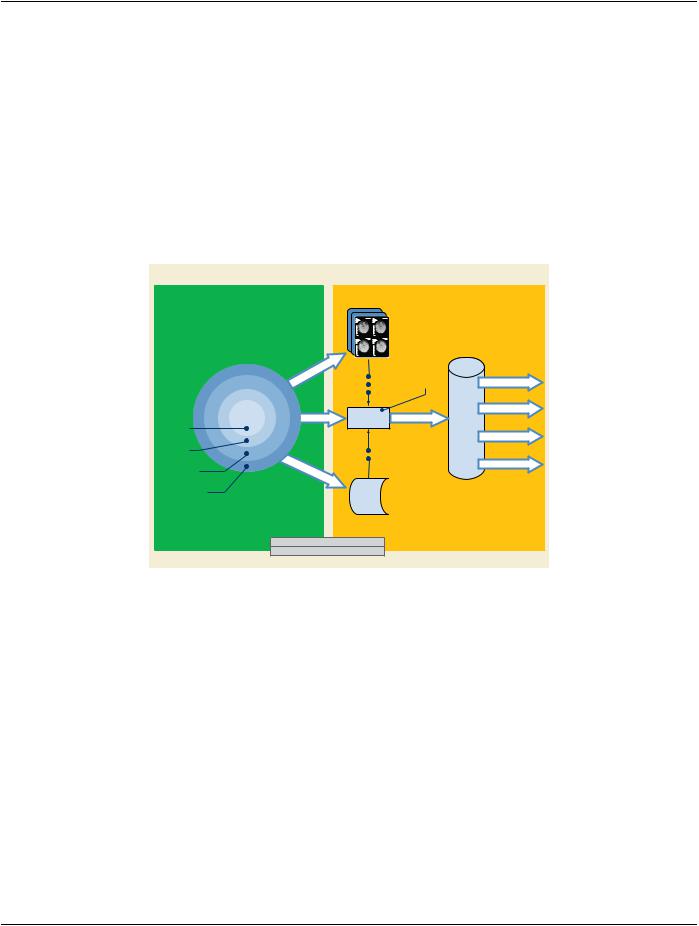
The Clinical Trial Identification modules are optional. As such, there are several points in the workflow of clinical trial or research data at which the Clinical Trial Identification Attributes may be added to the data. At the Clinical Trial Site, the Attributes may be added at the scanner, a PACS system, a site workstation, or a workstation provided to the site by a Clinical Trial Coordinating Center. If not added at the site, the Clinical Trial Identification Attributes may be added to the data after receipt by the Clinical Trial Coordinating Center. The addition of clinical trial Attributes does not itself require changes to the SOP Instance UID. However, the clinical trial or research protocol or the process of de-identification may require such a change.
Clinical Trial Site
CTCC
Workstation
PACS
Scanner
Add CTI at
SiteScanner
Add CTI at
PACS
Add CTI at
Workstation
Add CTI at CTCC
Workstation
Clinical Trial Coordinating Center
|
Media & Film |
|
|
|
|
COURIER |
|
|
|
Database |
|
Translation |
Add CTI |
QA/QC |
|||
|
|||||
|
Scanning |
at CTCC |
|||
|
|
||||
|
DICOMDIR |
|
|
||
|
DICOM |
|
|
Quant & Analysis |
|
DICOM PUSH |
DICOM PUSH |
|
|||
Inbox |
|
||||
|
|
|
|
||
|
|
|
|
Blinded Read |
|
|
Translation |
|
|
||
|
Transfer |
|
|
Submission |
|
FTP/e- |
|
|
|
||
|
|
|
|
||
|
|
|
|
||
|
Buffer |
|
|
|
|
CTI = Clinical Trial Identification Attributes |
|
|
|
||
CTCC = Clinical Trial Coordinating Center |
|
|
|
||
Figure H-1. Workflow Diagram for Clinical Trials
H.1 Example Use-case
Images are obtained for the purpose of comparing patients treated with placebo or the drug under test, then evaluated in a blinded manner by a team of radiologists at the Clinical Trial Coordinating Center (CTCC). The images are obtained at the clinical sites, col- lected by the CTCC, at which time their identifying Attributes are removed and the Clinical Trial Identification (CTI) module is added. The de-identified images with the CTI information are then presented to the radiologists who make quantitative and/or qualitative as- sessments. The assessments, and in some cases the images, are returned to the sponsor for analysis, and later are contributed to the submission to the regulating authority.
- Standard -

Page 128 |
DICOM PS3.17 2020a - Explanatory Information |
- Standard -
DICOM PS3.17 2020a - Explanatory Information |
Page 129 |
I Ultrasound Templates (Informative)
I.1 SR Content Tree Structure
Document Root
(CONTAINER)
|
|
|
|
|
|
|
|
|
|
|
|
|
|
|
|
|
|
|
|
|
|
|
|
|
|
|
|
|
|
|
|
|
|
|
|
|
|
|
|
|
|
|
|
|
|
|
|
|
|
|
|
|
|
|
|
|
|
|
CONTAINS |
|
|
|
|
|
|
|
|
|
|
|
|
|
|
|
|
|
|
|
|
|
|
|
||||
|
|
|
|
|
|
|
|
|
|
|
|
|
|
|
|
|
|
|
|
|
||||||||
|
|
|
|
|
|
|
|
|
|
CONTAINS |
|
|
|
|
|
|
|
|||||||||||
|
|
|
|
|
|
|
|
|
|
|
|
|
|
|
|
|
|
|
|
|
|
|
|
|
|
|||
|
|
|
|
|
|
|
|
|
|
|
|
|
|
|
|
|
|
|
|
|
|
|
|
|
|
|
||
|
|
|
|
|
|
|
|
|
|
|
|
|
|
|
|
|
|
|
|
|
|
|
|
|
|
|||
|
Patient Characteristics |
|
|
|
|
|
|
|
|
|
|
|
Image LIbrary |
|
|
|
|
|
|
|
|
|||||||
|
(CONTAINER) |
|
|
|
|
|
|
|
|
|
|
|
(CONTAINER) |
|
|
|
|
|
|
|
|
|||||||
|
|
|
|
|
|
|
|
|
|
|
|
|
|
|
|
|
|
|
|
|
|
|
|
|
|
|
|
|
|
|
|
|
|
|
|
|
|
|
|
|
|
|
|
|
|
|
|
|
|
|
|
|
|
|
|
|
|
|
CONTAINS |
|
|
CONTAINS |
CONTAINS |
CONTAINS |
||||||||||||||||||||||
|
|
|
|
|
|
|
|
|
|
|
|
|
|
|
|
|
|
|
|
|
|
|
|
|||||
|
|
|
|
|
|
|
|
|
|
|
|
|
|
|
|
|
|
|
|
|
|
|
|
|
||||
|
|
|
|
|
|
|
|
|
|
|
|
|
|
|
|
|
|
|
|
|
|
|
||||||
|
Observations |
|
|
Procedure Summary |
|
|
|
Image Entry |
|
|
|
Heading |
|
|
|
|||||||||||||
(NUM, CODE, TEXT, DATE) |
|
|
(CONTAINER) |
|
|
|
|
(IMAGE) |
|
|
(CONTAINER) |
|
||||||||||||||||
|
|
|
|
|
|
|
|
|
|
|
|
|
|
|
|
|
|
|
|
|
|
|
|
|
|
|
||
|
|
|
|
|
|
|
|
|
|
|
|
|
|
|
|
|
|
|
|
|
|
|
|
|
|
|
|
|
|
|
|
|
|
|
|
|
|
|
|
|
|
|
|
|
|
|
|
|
|
|
|
|
|
|
|
|
|
|
|
|
CONTAINS |
|
|
|
CONTAINS |
|
|
|
CONTAINS |
|
|
|
|
CONTAINS |
||||||||||||
|
|
|
|
|
|
|
|
|
|
|
|
|
|
|
|
|
|
|
|
|
|
|
|
|
|
|
|
|
|
|
|
|
|
|
|
|
|
|
|
|
|
|
|
|
|
|
|
|
|
|
|
|
|
|
|
|
|
|
|
|
|
|
|
|
|
|
|
|
|
|
|
|
|
|
|
|
|
|
|
|
|
|
|
|
|
|
|
|
|
Fetus Summary |
|
|
|
Observations |
|
|
|
Observations |
|
|
|
|
Measurement Group |
||||||||||||
|
|
|
(CONTAINER) |
|
|
(NUM, CODE, TEXT, DATE) |
|
(NUM, CODE, TEXT, DATE) |
|
|
(CONTAINER, CODE) |
|||||||||||||||||
|
|
|
|
|
|
|
|
|
|
|
|
|
|
|
|
|
|
|
|
|
|
|
|
|
|
|
|
|
|
|
|
|
|
|
|
|
|
|
|
|
|
|
|
|
|
|
|
|
|
|
|
|
|
|
|
|
|
|
|
|
|
|
|
|
|
|
|
|
|
|
|
|
|
|
|
|
|
|
|
|
|
|
|
CONTAINS |
||
|
|
|
|
|
|
|
|
|
|
|
|
|
|
|
|
|
|
|
|
|
|
|
|
|
|
|
|
|
|
|
|
|
|
|
|
|
|
|
|
|
|
|
|
|
|
|
|
|
|
|
|
|
|
|
|
|
|
|
|
|
|
|
|
|
|
|
|
|
|
|
|
|
|
|
|
|
|
|
|
|
|
|
|
|
|
|
|
|
|
|
|
|
|
|
|
|
|
|
|
|
|
|
|
|
|
|
|
|
|
|
|
|
Observations |
||
|
|
|
|
|
|
|
|
|
|
|
|
|
|
|
|
|
|
|
|
|
|
|
|
|
|
(NUM, CODE, TEXT) |
||
|
|
|
|
|
|
|
|
|
|
|
|
|
|
|
|
|
|
|
|
|
|
|
|
|
|
|
|
|
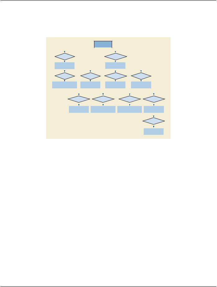
Figure I.1-1. Top Level Structure of Content Tree
The templates for ultrasound reports are defined in Annex A “Structured Reporting Templates (Normative)” in PS3.16. Figure I.1-1 is an outline of the common elements of ultrasound structured reports.
The Patient Characteristics Section is for medical data of immediate relevance to administering the procedure and interpreting the results. This information may originate outside the procedure.
TheProcedureSummarySectioncontainsexamobservationsofimmediateorprimarysignificance.Thisiskeyinformationaphysician typically expects to see first in the report.
Measurements typically reside in a measurement group container within a Section. Measurement groups share context such as anatomical location, protocol or type of analysis. The grouping may be specific to a product implementation or even to a user config- uration. OB-GYN measurement groups have related measurements, averages and other derived results.
Ifpresent,theImageLibrarycontainsalistofimagesfromwhichobservationswerederived.Thesearereferencedfromtheobservations with by-reference relationships.
I.2 Procedure Summary
TheProcedureSummarySectioncontainstheobservationsofmostimmediateinterest.Observationsintheproceduresummarymay have by-reference relationships to other content items.
I.3 Multiple Fetuses
Where multiple fetuses exist, the observations specific to each fetus must reside under separate section headings. The section heading must specify the fetus observation context and designate so using Subject ID (121030, DCM, "Subject ID") and/or numerical designation (121037, DCM, "Fetus Number") as shown below. See TID 1008 “Subject Context, Fetus”.
- Standard -
Page 130 |
DICOM PS3.17 2020a - Explanatory Information |
|
|
|
|
|
|
|
|
|
Document Root |
|
|
|
|
|
|
|
|||
|
|
|
|
|
|
|
|
|
(CONTAINER) |
|
|
|
|
|
|
|
|||
|
|
|
|
|
|
|
|
|
|
|
|
|
|
|
|
|
|
|
|
|
|
|
|
|
|
|
|
|
|
|
|
|
|
|
|
|
|
|
|
|
|
|
|
|
|
|
|
|
|
|
|
|
|
|
|
|
|
|
|
|
|
|
CONTAINS |
|
|
|
|
|
|
|
|
|
|
|
|
|
|
|
|
|
|
|
|
|
|
|
|
|
|
|
|
|
|
|
|
|
|
|
|
|
|
|
|
|
|
|
|
|
|
|
|
|
|
|
|
|
|
|
|
|
|
|
|
|
|
|
|
|
|
|
|
|
|
|
|
|
|
|
|
|
|
|
Procedure Summary |
|
|
|
|
|
|
|
|
|
|
|
|
|
|
|
|
|
|
|
|
|
|
|
|
|
|
|
|
|
|
|
|
|
|
||
|
|
|
(CONTAINER) |
|
|
|
|
|
|
|
|
|
|
|
|
|
|
|
|
|
|
|
|
|
|
|
|
|
|
|
|
|
|
|
|
|
|
||
|
|
|
|
|
|
|
|
|
|
|
|
|
|
|
|
|
|
||
|
|
|
|
|
|
|
|
|
CONTAINS |
|
|
CONTAINS |
|||||||
|
|
|
|
|
|
|
|
|
|
|
|
|
|
|
|
|
|
|
|
|
|
|
|
|
|
|
|
|
|
|
|
|
|
|
|
||||
CONTAINS |
|
CONTAINS |
|
|
|
|
FIRST Heading |
|
|
SECOND Heading |
|||||||||
|
|
|
|
|
(CONTAINER) |
|
|
(CONTAINER) |
|||||||||||
|
|
|
|
|
|
|
|
|
|
|
|||||||||
|
|
|
|
|
|
|
|
|
|
|
|
|
|
|
|
|
|
|
|
|
|
|
|
|
|
|
|
|
|
|
|
|
|
|
|
|
|
|
|
FIRST Fetus Summary |
|
SECOND Fetus Summary |
|
|
|
|
|
|
|
|
|
|
|
|
|
|
|
||
|
|
|
|
|
|
|
|
|
|
|
|
|
|
|
|
||||
(CONTAINER) |
|
(CONTAINER) |
|
HAS OBS |
HAS OBS |
||||||||||||||
|
|
|
|
|
|
||||||||||||||
|
|
|
|
|
|
CONTEXT |
CONTEXT |
||||||||||||
HAS OBS |
|
HAS OBS |
|
|
|
|
|
|
|
|
|
|
|
|
|
|
|
||
|
|
|
|
|
|
|
|
|
|
|
|
|
|
|
|
||||
CONTEXT |
|
CONTEXT |
|
Subject ID |
|
|
|
|
Subject ID |
|
|
||||||||
|
|
|
|
|
|
|
|
|
|
|
|||||||||
|
|
|
|
|
|
TEXT |
|
|
|
TEXT |
|
|
|||||||
|
|
|
|
|
|
|
|
|
|
|
|
|
|
|
|
|
|
|
|
|
|
|
|
|
|
|
|
|
|
|
|
|
|
|
|
|
|
|
|
Subject ID |
|
Subject ID |
|
|
|
|
|
|
|
|
|
|
|
|
|
|
|
||
TEXT |
|
TEXT |
|
|
|
|
|
|
|
|
|
|
|
|
|
|
|
||
|
|
|
|
|
|
|
|
|
|
|
|
|
|
|
|
|
|
|
|
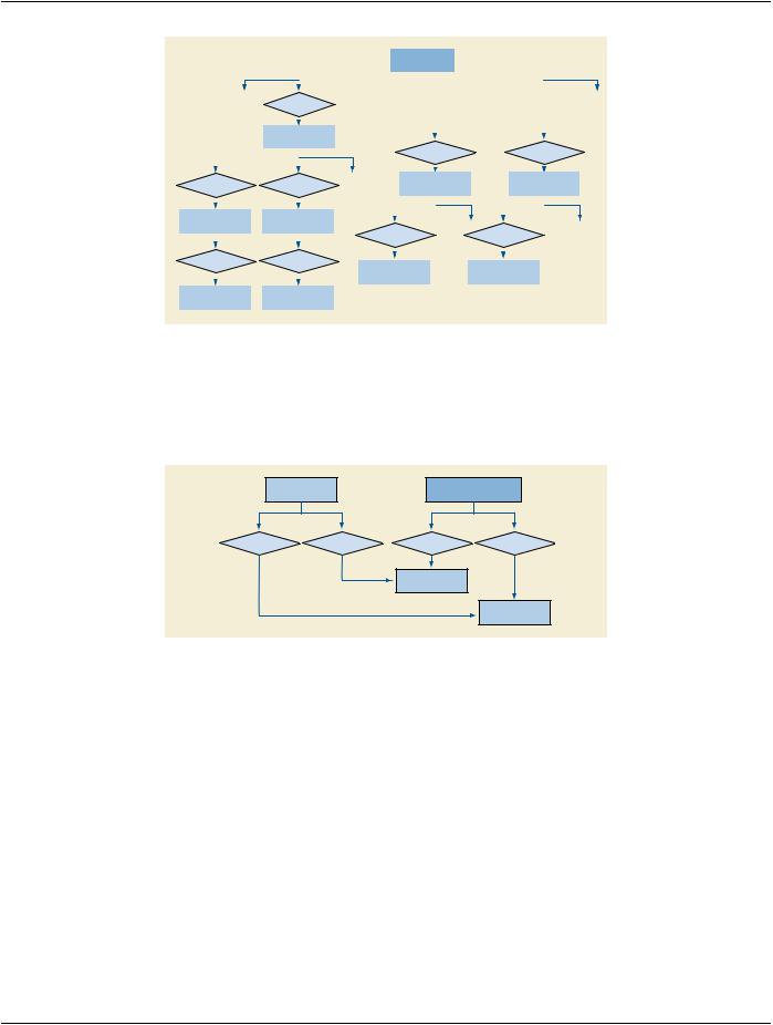
Figure I.3-1. Multiple Fetuses
I.4 Explicitly Specifying Calculation Dependencies
Reports may specify dependencies of a calculation on its dependent observations using by-reference relationships. This relationship must be present for the report reader to know the inputs of the derived value.
Cephalic Index |
|
Measurement Group |
|
NUM |
|
|
CONTAINER |
R-INFERRED |
R-INFERRED |
CONTAINS |
CONTAINS |
FROM |
FROM |
|
|
BPD
NUM =
OFD
NUM =
Figure I.4-1. Explicit Dependencies
I.5 Linking Measurements to Images, Coordinates
Optionally, the relationship of an observation to its image and image coordinates can be encoded with by-reference content items as Figure I.5-1 shows. For conciseness, the by-reference relationship points to the content item in the Image Library, rather than directly to the image.
- Standard -