

PS-2020a / part17
.pdfDICOM PS3.17 2020a - Explanatory Information |
Page 151 |
K Ultrasound Staged Protocol Data
Management (Informative)
K.1 Purpose of this Annex
The purpose of this annex is to enhance consistency and interoperability among creators and consumers of Ultrasound images within Staged Protocol Exams. An ultrasound "Staged Protocol Exam" is an exam that acquires a set of images under specified conditions during time intervals called "Stages". An example of such an exam is a cardiac stress-echo Staged Protocol.
This informative annex describes the use of ultrasound Staged Protocol Attributes within the following DICOM Services: Ultrasound Image, Ultrasound Multi-frame Image, and Key Object Selection Storage, Modality Worklist, and Modality Performed Procedure Step Services.
K.2 Prerequisites For Support
The support of ultrasound Staged Protocol Data Management requires support for the Ultrasound Image SOP Class or Ultrasound Multi-frame Image SOP Class as appropriate for the nature of the Protocol. By supporting some optional Elements of these SOP Classes, Staged-Protocols can be managed. Support of Key Object Selection allows control of the order of View and Stage present- ation. Support of Modality Worklist Management and Modality Performed Procedure Step allow control over specific workflow use cases as described in this Annex.
K.3 Definition of a Staged Protocol Exam
A "Staged Protocol Exam" acquires images in two or more distinct time intervals called "Stages" with a consistent set of images called "Views" acquired during each Stage of the exam. A View is of a particular cross section of the anatomy acquired with a specific ultra- sound transducer position and orientation. During the acquisition of a Staged Protocol Exam, the modality may also acquire non- Protocol images at one or more Protocol Stages.
Acommonreal-worldexampleofanultrasoundStagedProtocolexamisacardiacstress-echoultrasoundexam.Imagesareacquired in distinct time intervals (Stages) of different levels of stress and Views as shown in Figure K.3-1. Typically, stress is induced by meansofpatientexerciseormedication.TypicalStagesforsuchanexamarebaseline,mid-stress,peak-stress,andrecovery.During the baseline Stage the patient is at rest, prior to inducing stress through medication or exercise. At mid-stress Stage the heart is under a moderate level of stress. During peak-stress Stage the patient's heart experiences maximum stress appropriate for the patient's condition. Finally, during the recovery Stage, the heart recovers because the source of stress is absent.
At each Stage an equivalent set of Views is acquired. Examples of typical Views are parasternal long axis and parasternal short axis. Examination of wall motion between the corresponding Views of different Stages may reveal ischemia of one or more regions ("seg- ments") of the myocardium. Figure K.3-1 illustrates the typical results of a cardiac stress-echo ultrasound exam.
- Standard -

Page 152 |
DICOM PS3.17 2020a - Explanatory Information |
||||
|
|
|
STAGE |
|
|
|
|
Baseline |
Mid-Stress |
Peak-Stress |
Recovery |
|
|
1 |
2 |
3 |
4 |
|
Parasternal |
1 |
|
|
|
|
Long Axis |
|
|
|
|
|
|
|
|
|
|
VIEW |
Parasternal |
2 |
|
Short Axis |
|||
|
|
Extra-Protocol
Images
Figure K.3-1. Cardiac Stress-Echo Staged Protocol US Exam
K.4 Attributes Used in Staged Protocol Exams
The DICOM Standard includes a number of Attributes of significance to Staged Protocol Exams. This Annex explains how scheduling and acquisition systems may use these Attributes to convey Staged Protocol related information.
TableK.4-1listsalltheAttributesrelevanttoconveyStagedProtocolrelatedinformation(seePS3.3fordetailsabouttheseAttributes).
Table K.4-1. Attributes That Convey Staged Protocol Related Information
Modality Worklist |
US Image and US Multi-frame IOD |
MPPS IOD |
(Tag) [Return Key Type] |
(TAG) [Type] |
(Tag) [SCU/SCP Type] |
---- |
---- |
Scheduled Step Attributes Sequence |
|
|
(0040,0270) [1/1] (b) |
Study Instance UID (0020,000D)Study Instance UID (0020,000D) [1] |
>Study Instance UID (0020,000D) [1/1] |
|
[1] |
|
|
Scheduled Procedure Step |
Request Attributes Sequence (0040,0275) [3] (a,b) |
---- |
Sequence (0040,0100) |
|
|
>Scheduled Procedure Step |
>Scheduled Procedure Step Description (0040,0007)>Scheduled Procedure Step Description |
|
Description (0040,0007) [1C] |
[3] |
(0040,0007) [2/2] |
>Scheduled Protocol Code |
>Scheduled Protocol Code Sequence (0040,0008) [3]>Scheduled Protocol Code Sequence |
|
Sequence (0040,0008) [1C] |
|
(0040,0008) [2/2] |
---- |
PerformedProcedureStepDescription(0040,0254)[3]Performed Procedure Step Description |
|
|
|
(0040,0254) [2/2] |
---- |
Protocol Name (0018,1030) [3] |
Performed Series Sequence |
|
|
(0040,0340)>Protocol Name (0018,1030) |
|
|
[1/1] |
---- |
Performed Protocol Code Sequence (0040,0260) [3] Performed Protocol Code Sequence |
|
|
|
(0040,0260) [1/1] |
---- |
Number of Stages (0008,2124) [2C] |
---- |
---- |
Number of Views In Stage (0008,212A) [2C] |
---- |
---- |
Stage Name (0008,2120) [3] |
---- |
---- |
Stage Number (0008,2122) [3] |
---- |
- Standard -

|
DICOM PS3.17 2020a - Explanatory Information |
Page 153 |
|
Modality Worklist |
US Image and US Multi-frame IOD |
|
MPPS IOD |
(Tag) [Return Key Type] |
(TAG) [Type] |
|
(Tag) [SCU/SCP Type] |
---- |
Stage Code Sequence (0040,000A) [3] |
---- |
|
---- |
View Name (0008,2127) [3] |
---- |
|
---- |
View Number (0008,2128) [3] |
---- |
|
---- |
Number of Event Timers (0008,2129) [3] |
---- |
|
---- |
Event Elapsed Time(s) (0008,2130) [3] |
---- |
|
---- |
Event Timer Name(s) (0008,2132) [3] |
---- |
|
---- |
View Code Sequence (0054,0220) [3] |
---- |
|
---- |
>View Modifier Code Sequence (0054,0222) [3] |
---- |
|
a.Recommended if the Modality conforms as an SCU to the Modality Worklist SOP Class and Modality Performed Procedure Step
b.Sequence may have one or more Items
K.5 Guidelines
This annex provides guidelines for implementation of the following aspects of Staged Protocol exams:
•Identification of a Staged Protocol exam.
•Identification of Stages and Views within a Staged Protocol exam.
•Identification of extra-Protocol images within a Staged Protocol exam.
•Acquisition of multiple images of a View during a Stage, and identification of the preferred image for that Stage.
•Workflow management of Staged Protocol images.
K.5.1 Staged Protocol Exam Identification
TheAttributesNumberofStages(0008,2124)andNumberofViewsinStage(0008,212A)areeachType2Cwiththecondition"Required if this image was acquired in a Staged Protocol." These two Attributes will be present with values in image SOP Instances if the exam meets the definition of a Staged Protocol Exam stated in Section K.3. This includes both the Protocol View images as well as any extra-Protocol images acquired during the Protocol Stages.
The Attributes Protocol Name (0018,1030) and Performed Protocol Code Sequence (0040,0260) identify the Protocol of a Staged Protocol Exam, but the mere presence of one or both of these Attributes does not in itself identify the acquisition as a Staged Protocol Exam.IfbothProtocolNameandPerformedProtocolCodeSequenceAttributesarepresent,theProtocolNamevaluetakesprecedence over the Performed Protocol Code Sequence Code Meaning value as a display label for the Protocol, since the Protocol Name would convey the institutional preference better than the standardized code meaning.
K.5.2 Stage and View Identification
Display devices usually include capabilities that aid in the organization and presentation of images acquired as part of the Staged Protocol. These capabilities allow a clinician to display images of a given View acquired during different Stages of the Protocol side by side for comparison. A View is a particular combination of the transducer position and orientation at the time of image acquisition. ImagesareacquiredatthesameViewindifferentProtocolStagesforthepurposeofcomparison.Forthesefeaturestoworkproperly, the display device must be able to determine the Stage and View of each image in an unambiguous fashion.
There are three possible mechanisms for conveying Stage and View identification in the image SOP Instances:
•"Numbers" (Stage Number (0008,2122) and View Number (0008,2128) ), which number Stages and Views, starting with one.
•"Names"(StageName(0008,2120)andViewName(0008,2127)),whichspecifytextualnamesforeachStageandView,respectively.
- Standard -

Page 154 |
DICOM PS3.17 2020a - Explanatory Information |
•"Code sequences" (Stage Code Sequence (0040,000A) for Stage identification, and View Code Sequence (0054,0220) for View identification), which give identification "codes" to the Stage and View respectively.
The use of code sequences to identify Stage and View, using Context Group values specified in PS3.16 (e.g., CID 12002 “Ultrasound Protocol Stage Types” and CID 12226 “Echocardiography Image View”), allows a display application with knowledge of the code se- mantics to render a display in accordance with clinical domain uses and user preferences (e.g., populating each quadrant of an echocardiographic display with the user desired stage and view). The IHE Echocardiography Workflow Profile requires such use of code sequences for stress-echo studies.
Table K.5-1 provides an example of the Staged Protocol relevant Attributes in images acquired during a typical cardiac stress-echo ultrasound exam.
Table K.5-1. Staged Protocol Image Attributes Example
Baseline Stage - View 1 |
Mid-Stress Stage - View 1 |
Mid-Stress Stage - View 2 |
Study Instance UID: |
Study Instance UID: |
Study Instance UID: |
"1.2.840….123.1" |
"1.2.840….123.1" |
Request Attributes Sequence: |
Request Attributes Sequence: |
>Scheduled Procedure Step Description:>Scheduled Procedure Step Description: |
|
"Exercise stress echocardiography" |
"Exercise stress echocardiography" |
>Scheduled Protocol Code Sequence: |
>Scheduled Protocol Code Sequence: |
>>Code Value: "433233004" |
>>Code Value: "433233004" |
>>Coding Scheme Designator: "SCT" |
>>Coding Scheme Designator: "SCT" |
>>Code Meaning: "Exercise stress |
>>Code Meaning: "Exercise stress |
echocardiography" |
echocardiography" |
Performed Procedure Step Description:Performed Procedure Step Description: |
|
"Exercise stress echocardiography" |
"Exercise stress echocardiography" |
Protocol Name: |
Protocol Name: |
"1.2.840….123.1"
 Request Attributes Sequence:
>Scheduled Procedure Step Description: "Exercise stress echocardiography"
 >Scheduled Protocol Code Sequence:
>>Code Value: "433233004"
 >>Coding Scheme Designator: "SCT"
>>Code Meaning: "Exercise stress echocardiography"
Performed Procedure Step Description: "Exercise stress echocardiography"
Protocol Name:
"EXERCISE STRESS-ECHO" |
"EXERCISE STRESS-ECHO" |
"EXERCISE STRESS-ECHO" |
Performed Protocol Code Sequence: |
Performed Protocol Code Sequence: |
Performed Protocol Code Sequence: |
>Code Value: "433233004" |
>Code Value: "433233004" |
>Code Value: "433233004" |
>Coding Scheme Designator: "SCT" |
>Coding Scheme Designator: "SCT" |
>Coding Scheme Designator: "SCT" |
>Code Meaning: "Exercise stress |
>Code Meaning: "Exercise stress |
>Code Meaning: "Exercise stress |
echocardiography" |
echocardiography" |
echocardiography" |
Number of Stages: "4" |
Number of Stages: "4" |
Number of Stages: "4" |
Number of Views In Stage: "2" |
Number of Views In Stage: "2" |
Number of Views In Stage: "2" |
Stage Name: "BASELINE" |
Stage Name: "MID-STRESS" |
Stage Name: "MID-STRESS" |
Stage Number: "1" |
Stage Number: "2" |
Stage Number: "2" |
Stage Code Sequence: |
Stage Code Sequence: |
Stage Code Sequence: |
>Code Value:"128974000" |
>Code Value: "109091" |
>Code Value: "109091" |
>Coding Scheme Designator: "SCT" |
>Coding Scheme Designator: "DCM" |
>Coding Scheme Designator: "DCM" |
>Code Meaning: "Baseline state" |
>Code Meaning: "Cardiac Stress State" |
>Code Meaning: "Cardiac Stress State" |
View Name: "Para-sternal long axis" |
View Name: "Para-sternal long axis" |
View Name: "Para-sternal short axis" |
View Number: "1" |
View Number: "1" |
View Number: "2" |
---- |
Number of Event Timers: "1" |
Number of Event Timers: "1" |
---- |
Event Elapsed Time(s): "10000" (ms) |
Event Elapsed Time(s): "25000" (ms) |
---- |
Event Elapsed Timer Name(s): "Time SinceEvent Elapsed Timer Name(s): "Time Since |
|
|
Exercise Halted" |
Exercise Halted" |
- Standard -

|
DICOM PS3.17 2020a - Explanatory Information |
Page 155 |
|
Baseline Stage - View 1 |
Mid-Stress Stage - View 1 |
Mid-Stress Stage - View 2 |
|
View Code Sequence: |
View Code Sequence: |
View Code Sequence: |
|
>Code Value: "399139001" |
>Code Value: "399139001" |
>Code Value: "399306005" |
|
>Coding Scheme Designator: "SCT" |
>Coding Scheme Designator: "SCT" |
>Coding Scheme Designator: "SCT" |
|
>Code Meaning: "Parasternal long axis">Code Meaning: "Parasternal long axis" |
>Code Meaning: "Parasternal short axis" |
||
K.5.3 Extra-protocol Image Identification
At any Stage of a Staged Protocol exam, the operator may acquire images that are not part of the Protocol. These images are so- called "extra-Protocol images". Information regarding the performed Protocol is still included because such images are acquired in thesameProcedureStepastheProtocolimages.TheStagenumberandoptionallyotherStageidentificationAttributes(StageName and/or Stage Code Sequence) should still be conveyed in extra-Protocol images. However, the View number should be omitted to signify that the image is not one of the standard Views in the Protocol. Other View identifying information, such as name or code se- quences, may indicate the image location.
Table K.5-2. Comparison Of Protocol And Extra-Protocol Image Attributes Example
Mid-Stress Stage - View 1
Protocol Image
Study Instance UID:
"1.2.840….123.1"
 Request Attributes Sequence:
>Scheduled Procedure Step Description: " Exercise stress echocardiography protocol"
 >Scheduled Protocol Code Sequence:
>>Code Value: " 433233004"
 >>Coding Scheme Designator: "SCT"
>>Code Meaning:" Exercise stress echocardiography"
Performed Procedure Step Description: "Exercise stress echocardiography"
Protocol Name:
"EXERCISE STRESS-ECHO"
 Performed Protocol Code Sequence:
>Code Value: "433233004"
 >Coding Scheme Designator: "SCT"
>Code Meaning:" Exercise stress echocardiography"
 Number of Stages: "4"
Number of Views In Stage: "2"
 Stage Name: "MID-STRESS"
Stage Number: "2"
 Stage Code Sequence:
>Code Value: "109091"
 >Coding Scheme Designator: "DCM"
>Code Meaning: "Cardiac Stress state"
 View Name: "Para-sternal long axis" View Number: "1"
Mid-Stress Stage
Extra-Protocol Image
Study Instance UID:
"1.2.840….123.1"
 Request Attributes Sequence:
>Scheduled Procedure Step Description: " Exercise stress echocardiography protocol"
 >Scheduled Protocol Code Sequence:
>>Code Value: " 433233004"
 >>Coding Scheme Designator: "SCT" >>Code Meaning:" Exercise stress echocardiography"
Performed Procedure Step Description: "Exercise stress echocardiography"
Protocol Name:
"EXERCISE STRESS-ECHO"
 Performed Protocol Code Sequence:
>Code Value: "433233004"
 >Coding Scheme Designator: "SCT"
>Code Meaning:" Exercise stress echocardiography"
 Number of Stages: "4"
Number of Views In Stage: "2"
 Stage Name: "MID-STRESS"
Stage Number: "2"
 Stage Code Sequence:
>Code Value: "109091"
 >Coding Scheme Designator: "DCM"
>Code Meaning: "Cardiac Stress state"
 ----
----
----
- Standard -
Page 156 |
DICOM PS3.17 2020a - Explanatory Information |
|
Mid-Stress Stage - View 1 |
Mid-Stress Stage |
|
Protocol Image |
Extra-Protocol Image |
|
View Code Sequence: |
|
---- |
>Code Value: "399139001" |
|
---- |
>Coding Scheme Designator: "SCT" |
|
---- |
>Code Meaning: "Parasternal long axis" |
---- |
|
K.5.4 Multiple Images of A Stage-view
Ultrasound systems often acquire multiple images at a particular stage and view. If one image is difficult to interpret or does not fully portray the ventricle wall, the physician may choose to view an alternate. In some cases, the user may identify the preferred image. The Key Object Selection Document can identify the preferred image for any or all of the Stage-Views. This specific usage of the Key Object Selection Document has a Document Title of (113013, DCM, "Best In Set") and Document Title Modifier of (113017, DCM, "Stage-View").
K.5.5 Workflow Management of Staged Protocol Images
K.5.5.1 Uninterrupted Exams - Single MPPS
Modality Performed Procedure Step (MPPS) is the basic organizational unit of Staged Protocol Exams. It is recommended that a single MPPS instance encompass the entire acquisition of an ultrasound Staged Protocol Exam if possible.
There are no semantics assigned to the use of Series within a Staged Protocol Exam other than the DICOM requirements as to the relationship between Series and Modality Performed Procedure Steps. In particular, all of the following scenarios are possible:
•one Series for all images in the MPPS.
•separate Series for Protocol View images and extra-Protocol images in the MPPS.
•separate Series for images of each Stage within the MPPS.
•more than one Series for the images acquired in a single Protocol Stage.
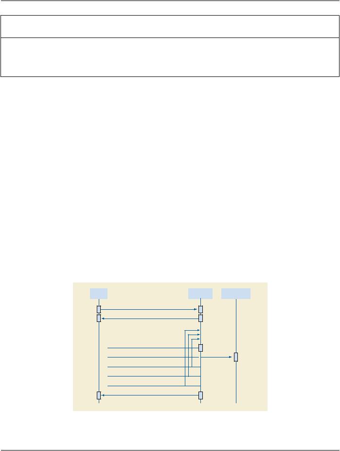
There is no recommendation on the organization of images into Series because clinical events make such recommendations imprac- tical. Figure K.5.5-1 shows a possible sequence of interactions for a protocol performed as a single MPPS.
Worklist |
|
Acquisition |
|
Storage |
Manager |
|
Modality |
|
Server |
|
|
|
|
|
1. Modality Worklist Provides Scheduled Staged Protocol
2.MPPS Created for Scheduled Staged Protocol
3. Acquire Image
4.Store Image
5.Acquire Stage-View
6.Acquire Next View
7Acquire Next Stage
8. MPPS Set “COMPLETED” for Scheduled Staged Protocol
Figure K.5.5-1. Example of Uninterrupted Staged-Protocol Exam WORKFLOW
- Standard -
DICOM PS3.17 2020a - Explanatory Information |
Page 157 |
K.5.5.2 Interrupted Exams - Multiple MPPS
A special case arises when the acquisition during a Protocol Stage is halted for some reason. For example, such a situation can occur if signs of patient distress are observed, such as angina in a cardiac stress exam. These criteria are part of the normal exam Protocol, and as long as the conditions defined for the Protocol are met the MPPS status is set to COMPLETED. Only if the exam terminates before meeting the minimum acquisition requirements of the selected Protocol would MPPS status be set to DISCONTINUED. It is recommended that the reason for discontinuation should be conveyed in the Modality Procedure Step Discontinuation Reason Code Sequence(0040,0281).StagedProtocolsgenerallyincludecriteriaforendingtheexam,suchaswhenatargettimedurationisreached or if signs of patient distress are observed.
If a Protocol Stage is to be acquired at a later time with the intention of using an earlier completed Protocol Stage of a halted Staged Protocol then a new Scheduled Procedure Step may or may not be created for this additional acquisition. Workflow management re- commendations vary depending on whether the care institution decides to create a new Scheduled Procedure Step or not.
Follow-upStagesmustuseViewNumbers,Names,andCodeSequencesidenticaltothoseinthepriorStagestoenableautomatically correlating images of the original and follow-up Stages.
K.5.5.2.1 Unscheduled Follow-up Stages
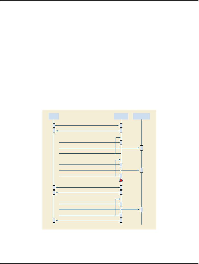
Follow-up Stages require a separate MPPS. Since follow-up stages are part of the same Requested Procedure and Scheduled Pro- cedure Step, all acquired image SOP Instances and generated MPPS instances specify the same Study Instance UID. If the Study InstanceUIDisdifferent,systemswillhavedifficultyassociatingrelatedimages.ThiscreatesasignificantproblemifModalityWorklist is not supported. Therefore systems should assign the same Study Instance UID for follow-up Stages even if Modality Worklist is not supported. Figure K.5.5-2 shows a possible interaction sequence for this scenario.
Worklist |
|
Acquisition |
|
Storage |
Manager |
|
Modality |
|
Server |
|
|
|
|
|
1. Modality Worklist Provides Scheduled Staged Protocol
2.MPPS Created for Scheduled Staged Protocol
3. Acquire Images
4.Store Images
5.Acquire Baseline Stage
6. Acquire Images
7. Store Images
8. Begin Stress Stage(s)
Halt Exam Early Due to Patient Distress
9. MPPS Set “COMPLETED” for Scheduled Staged Protocol
10. Second MPPS Created for ‘Follow-up’ Scheduled Protocol
11. Acquire Images
12. Store Images
13. Acquire Stress and Recovery Stages
14. MPPS Set “COMPLETED” for ‘Follow-up’ Scheduled Staged Protocol
Figure K.5.5-2. Example Staged-Protocol Exam with Unscheduled Follow-up Stages
- Standard -

Page 158 |
DICOM PS3.17 2020a - Explanatory Information |
K.5.5.2.2 Scheduled Follow-up Stages
In some cases a new Scheduled Procedure Step is created to acquire follow-up Stages. For example, a drug induced stress-echo exam may be scheduled because an earlier exercise induced stress-echo exam had to be halted due to patient discomfort. In such cases it would be redundant to reacquire earlier Stages such as the rest Stage of a cardiac stress-echo ultrasound exam. One MPPS contains the Image instances of the original Stage and a separate MPSS contains the follow-up instances.
If Scheduled and Performed Procedure Steps for Staged Protocol Exam data use the same Study Instance UID, workstations can associate images from the original and follow-up Stages. Figure K.5.5-3 shows a possible interaction sequence for this scenario.
Worklist |
|
Acquisition |
|
Storage |
Manager |
|
Modality |
|
Server |
|
|
|
|
|
1. Modality Worklist Provides Scheduled Staged Protocol
2.MPPS Created for Scheduled Staged Protocol
3. Acquire Images
4.Store Images
5.Acquire Baseline Stage
6. Acquire Images
7. Store Images
8. Begin Stress Stage(s)
Halt Exam Early Due to Patient Distress
9. MPPS Set “COMPLETED” for Scheduled Staged Protocol
10. Modality Worklist Provides New Follow-up Scheduled Staged Protocol
(same Study UID as original)
11.MPPS Created for ‘Follow-up’ Scheduled Protocol
12. Acquire Images
13. Store Images
14. Acquire Stress and Recovery Stages
15. MPPS Set “COMPLETED” for ‘Follow-up’ Scheduled Staged Protocol
Figure K.5.5-3. Example Staged-Protocol Exam with Scheduled Follow-up Stages
- Standard -
DICOM PS3.17 2020a - Explanatory Information |
Page 159 |
L Hemodynamics Report Structure (Informative)
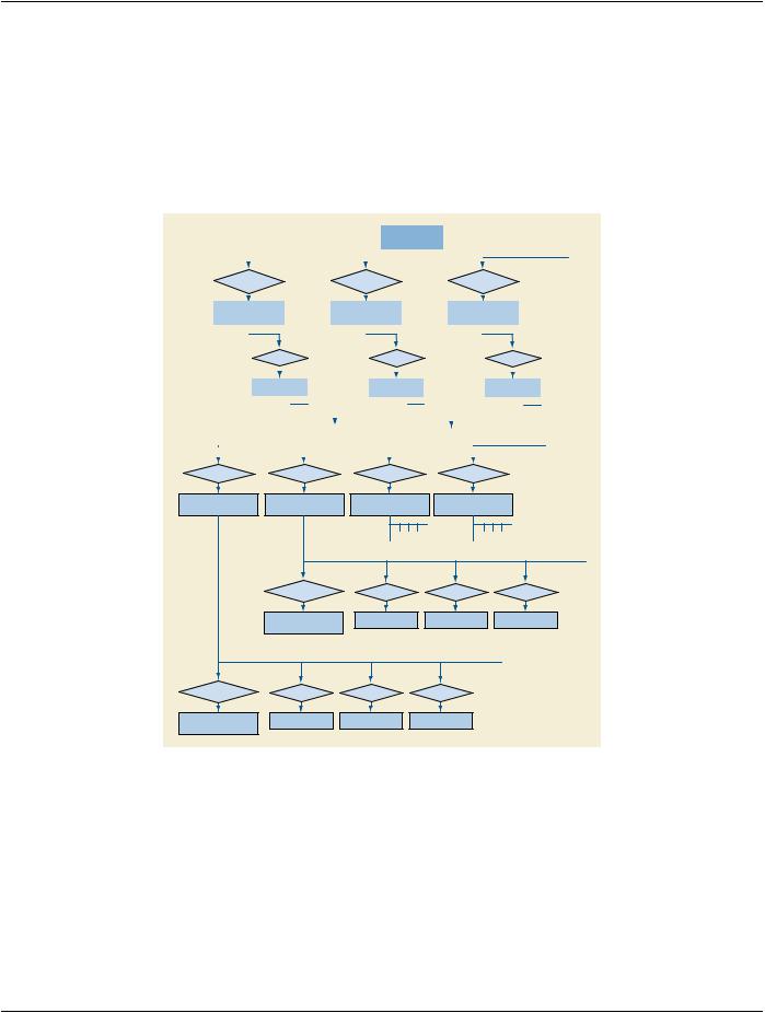
TheHemodynamicsReportisbasedonTID3500“HemodynamicsReport”.Thereportcontainsoneormoremeasurementcontainers, each corresponding to a phase of the cath procedure. Within each container may be one or more sub-containers, each associated withasinglemeasurementset.Ameasurementsetconsistsofmeasurementsfromasingleanatomiclocation.Theresultinghierarch- ical structure is depicted in Figure L-1.
|
|
|
|
|
|
|
|
|
|
|
|
|
|
Document Root |
|
|
|
|
|
|
|
|
|
|||||
|
|
|
|
|
|
|
|
|
|
|
|
|
|
(CONTAINER) |
|
|
|
|
|
|
|
|
|
|||||
|
|
|
|
|
|
|
|
|
|
|
|
|
|
|
|
|
|
|
|
|
|
|
|
|
|
|
|
|
|
|
|
|
|
|
|
|
|
|
|
|
|
|
|
|
|
|
|
|
|
|
|
|
|
|
|
|
|
|
|
|
|
|
|
|
|
|
|
|
|
|
|
|
|
|
|
|
|
|
|
|
|
|
|
|
|
|
|
CONTAINS |
|
CONTAINS |
|
|
CONTAINS |
||||||||||||||||||||||
|
|
|
|
|
|
|
|
|
|
|
|
|
|
|
|
|
|
|
|
|
|
|
|
|
|
|
|
|
|
|
|
|
|
|
|
|
|
|
|
|
|
|
|
|
|
|
|
|
|
|
|
|
|
|
|
|
|
|
|
|
|
|
|
|
|
|
|
|
|
|
|
|
|
|
|
|
|
|
|
|
|
|
|
|||
|
Baseline Phase |
|
|
|
|
|
Post-Contrast Phase |
|
|
|
|
Post-Intervention Phase |
|
|
||||||||||||||
|
(CONTAINER) |
|
|
|
|
|
(CONTAINER) |
|
|
|
|
|
(CONTAINER) |
|
|
|||||||||||||
|
|
|
|
|
|
|
|
|
|
|
|
|
|
|
|
|
|
|
|
|
|
|
|
|
|
|
|
|
|
|
|
CONTAINS |
|
|
|
CONTAINS |
|
|
|
|
CONTAINS |
||||||||||||||||
|
|
|
|
|
|
|
|
|
|
|||||||||||||||||||
|
|
|
|
|
|
|
|
|
|
|
|
|
|
|
|
|
|
|
|
|
|
|||||||
|
|
|
|
|
|
|
|
|
|
|
|
|
|
|
|
|
|
|
|
|
|
|
|
|
|
|
|
|
|
|
|
|
|
|
|
|
|
|
|
|
|
|
|
|
|
|
|
|
|
|
|
|
|
|
|
|
|
|
|
|
Clinical Context |
|
|
|
Clinical Context |
|
|
|
|
|
Clinical Context |
|||||||||||||||
|
|
|
(CONTAINER) |
|
|
|
(CONTAINER) |
|
|
|
|
|
(CONTAINER) |
|||||||||||||||
|
|
|
|
|
|
|
|
|
|
|
|
|
|
|
|
|
|
|
|
|
|
|
|
|
|
|
|
|
|
|
|
|
|
|
|
|
|
|
|
|
|
|
|
|
|
|
|
|
|
|
|
|
|
|
|
|
|
|
|
|
|
|
|
|
|
|
|
|
|
|
|
|
|
|
|
|
|
|
|
|
|
|
|
|
|
|
|
|
|
|
|
|
|
|
|
|
|
|
|
|
|
|
|
|
|
|
|
|
|
|
|
|
|
|
|
|
|
|
|
|
|
|
|
|
|
|
|
|
|
|
|
|
|
|
|
|
|
|
|
|
|
|
|
|
CONTAINS |
CONTAINS |
CONTAINS |
CONTAINS |
Arterial Measurements |
Arterial Measurements |
Ventricular Measurements |
Gradient Measurements |
(CONTAINER) |
(CONTAINER) |
(CONTAINER) |
(CONTAINER) |
HAS OBS CONTEXT
Anatomic Location
LOC = Aorta
CONTAINS |
CONTAINS |
CONTAINS |
Systolic Pres. |
Diastolic Pres. |
Mean Pres. |
HAS OBS CONTEXT
Anatomic Location
LOC = L Fem Art
CONTAINS |
CONTAINS |
CONTAINS |
Systolic Pres. |
Diastolic Pres. |
Mean Pres. |
Figure L-1. Hemodynamics Report Structure
ThecontainerforeachphasehasanoptionalsubsidiarycontainerforClinicalContextwithaparent-childrelationshipofhas-acquisition- context.ThisClinicalContextcontainerallowstherecordingofpertinentpatientstateinformationthatmaybeessentialtounderstanding the measurements made during that procedure phase. It should be noted that any such patient state information is necessarily only a summary; a more complete clinical picture may be obtained by review of the cath procedure log.
The lowest level containers for the measurement sets are specialized by the class of anatomic location - arterial, venous, atrial, ventricular - for the particular measurements appropriate to that type of location. These containers explicitly identify the anatomic location with a has-acquisition-context relationship. Since such measurement sets are typically measured on the same source (e.g., pressurewaveform),thecontainermayalsohaveahas-acquisition-contextrelationshipwithasourceDICOMwaveformSOPInstance.
- Standard -

Page 160 |
DICOM PS3.17 2020a - Explanatory Information |
The "atomic" level of measurements within the measurement set containers includes three types of data. First is the specific meas- urement data acquired from waveforms related to the site. Second is general measurement data that may include any hemodynamic, patient vital sign, or blood chemistry data. Third, derived data are produced from a combination of other data using a mathematical formula or table, and may provide reference to the equation.
- Standard -