

4.3 Vernier scale
P. Vernier showed how lengths can be measured accurately. He used a subsidiary scale, now called a vernier scale. Fig. 4.1a shows the vernier scale Y below the main scale X, which is graduated in centimeters and millimeters. 10 divisions on Y make 9 mm. Thus the length between each division on Y is 0 ÷ 9 mm, which is 0.1 mm or 0.01 cm less than the length of the divisions on X.
Fig. 4.1b shows the vernier scale Y moved to measure the length of a rod R. X
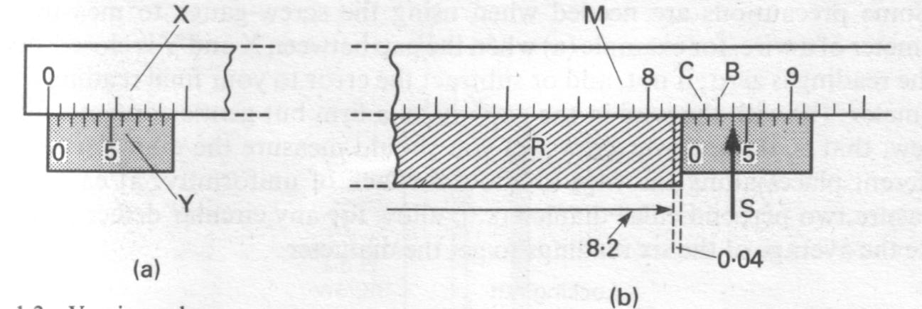
Figure 4.1 – Vernier scale
The length of R is greater than 8.2 but less than 8.3 cm. We now note the division S on Y which coincides with a division on M. This is the fourth division on Y. The third division on Y is thus 0.01 cm in front of the graduation B, the 2nd division on Y is 0.02 cm in front of the graduation C, and so on. Hence the zero of Y is MM cm in front of the 8.2 cm reading on M. Hence the length of R is 8.24 cm.
Fig. 4.2 shows a form of vernier calipers. The object measured is placed between the jaws X and Y, and its length are read from the main and vernier scales as explained above.
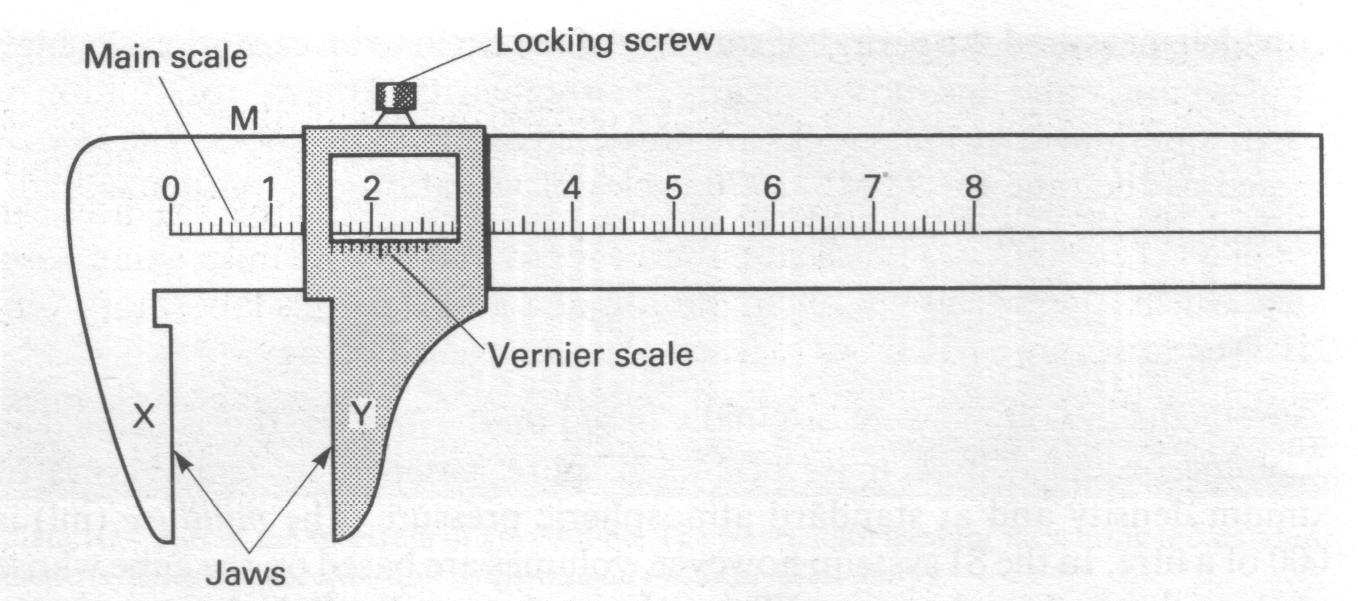
Figure 4.2 –Vernier calipers
4.4 Micrometer screw gauge
The micrometer screw gauge is an instrument for measuring accurately the diameters of wires or thin rods. It uses an accurate screw of known 'pitch' such as 0÷5 mm, shown inset in Fig. 4.3. This means that for one revolution of the screw the spindle X moves forward or back 0÷5 mm.
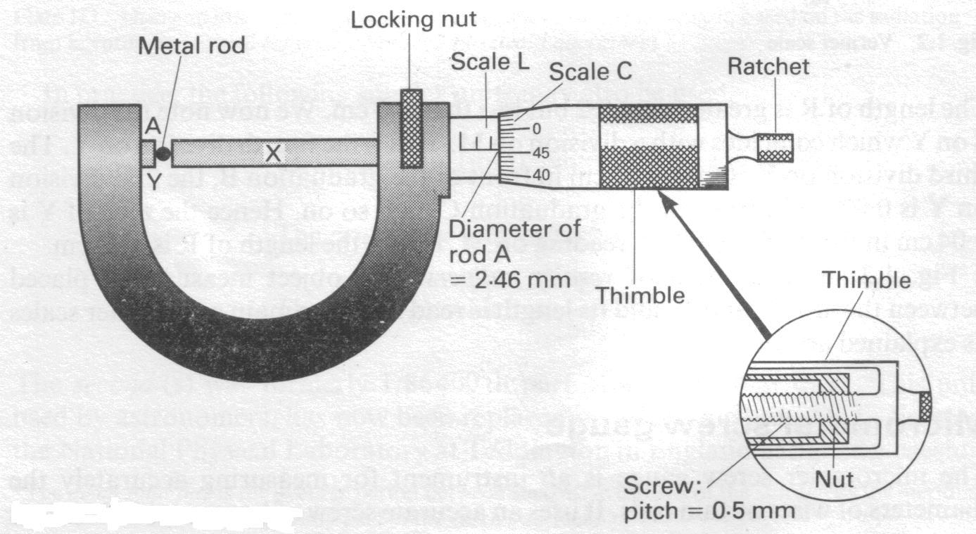
Figure 4.3 – Micrometer gauge
To measure the diameter of a wire or rod A, one side is rested on the end Y and the thimble is turned until the end of the spindle X just touches A. Further turning of the thimble does not make the spindle move forward because a ratchet stops excessive pressure on A. A locking device is sometimes included so that the diameter reading can be read after A is taken out.
An engraved linear millimeters scale L shows the forward movements of the spindle. A circular scale C on the thimble helps to measure fractions of millimeters. In Fig. 4.4, 50 circular divisions = 0.5 mm, or 1 circular division = 0.01 mm. So from Fig. 4.4, diameter of rod = 2.0 mm (scale L) + 46 × 0.01 mm (scale C) = 2.46 mm
Some precautions are needed when using the screw-gauge to measure the diameter of a wire, for example (a) when the gap between X and Y is closed, check if the reading is zero; if not, add or subtract the error to your final reading of the diameter: (b) with the wire in the gap, make a firm but gentle contact with the screw, that is, do not over screw: (c) you should measure the diameter at three different places along the wire to allow for lack of uniformity; at each place, measure two perpendicular diameters to allow for any circular defect and then take the average of the six readings to get the diameter.
4.5 Measurement of mass
The mass of an object can be measured by comparing it with standard masses. These are derived from copies of the International Kilogram Mass. The chemical balance is used to compare masses in this way. Extremely sensitive balances can be designed. The National Physical Laboratory at Teddington in England has a balance which can measure to one-millionth of a gram. At this laboratory very precise weightings are carried out to assist science and technology.
School balances do not require such high precision. The design of chemical balances has altered so much in recent years that the types used will generally differ from school to school. The top pan balance gives direct reading of mass. It does this by comparing the unknown mass with movable known masses inside it. As in the common balance, the unknown and known masses are balanced using a lever arrangement.
If an object is taken say from London, England, to Lagos, Nigeria, or anywhere else in the world, and weighed on any other chemical balance, its mass will be exactly the same. So a chemical balance compares masses.