

Структурная схема сау газотурбинной установки гтк-10-4
ACS functional diagram development
The ACS block diagram gives only the general notion about a system structure and methods of connection of CO and the main automatic devices, which are included in a system. For detailed study of an operation principle of each governor or the automatic control unit it is necessary to consider their functional diagrams.
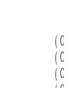
Examples of Controller (regulator) functional elements symbolic representation
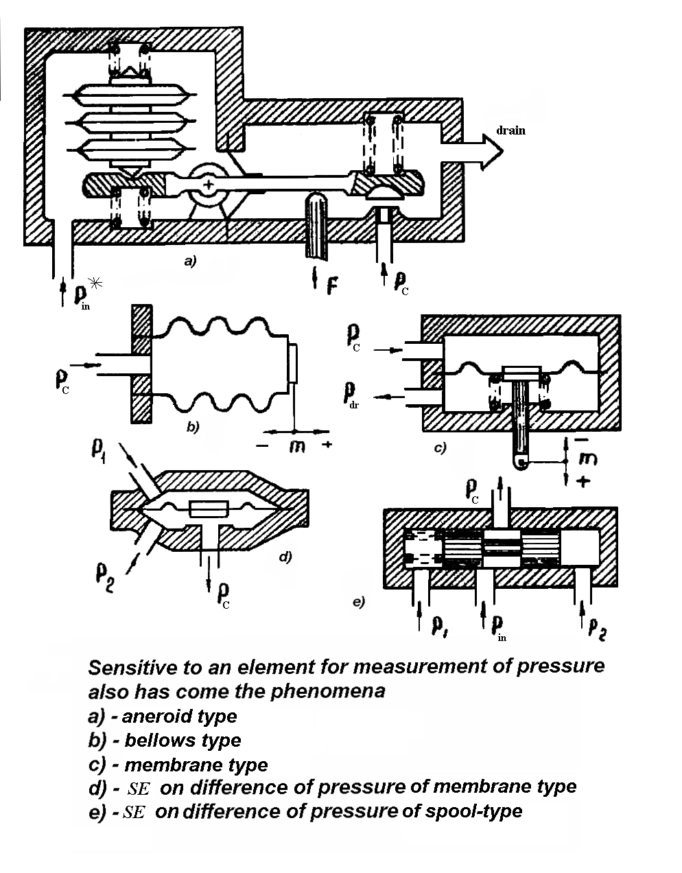
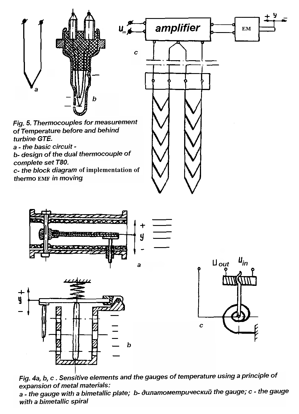
Elemental Base of Automatic Control system of GTP

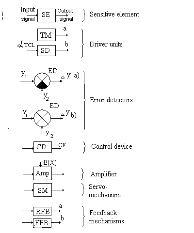
Examples of Control Devices for controlling liquide
and gaseous fuel

. Схема регулюючого клапана:
1 – корпус; 2 – пружина; 3 – мембрана; 4 – регулюючий клапан (керуючий орган); 5 – сідло клапана
Additional page to collection of illustrative materials
Schematic Diagrams
of
Different types of Engine Rotor Speed Governors
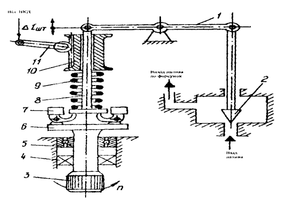
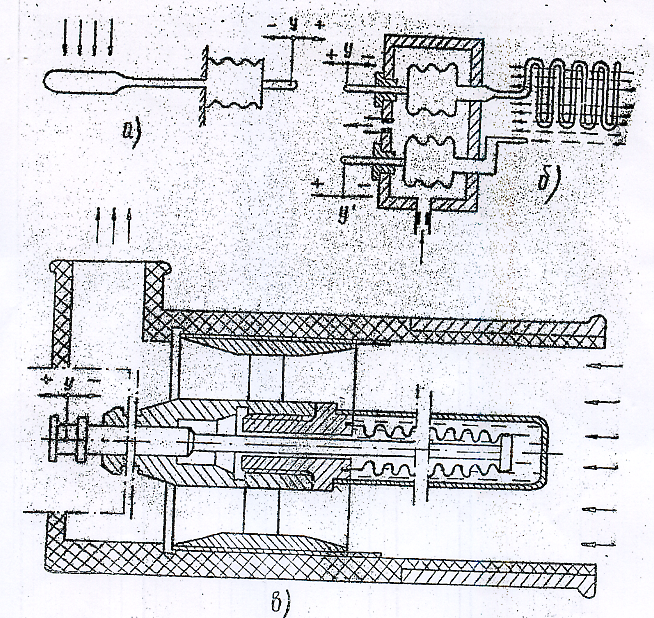
Fig. 1 Direct action (Self operation ) rotor speed governor (controller)
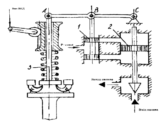
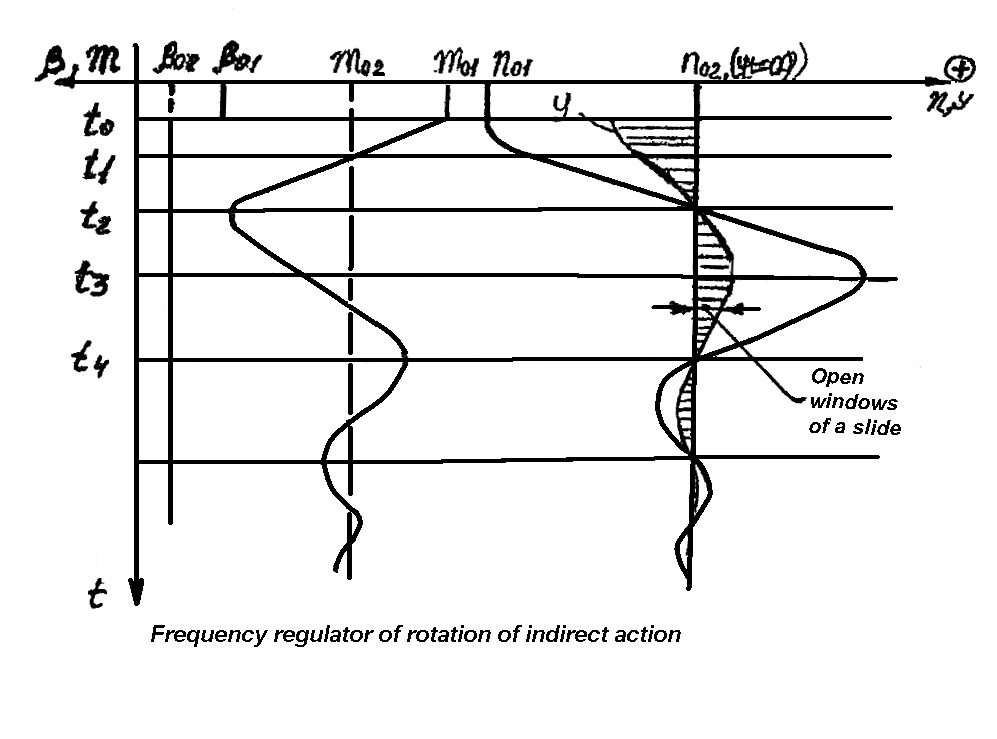
Fig. 2 Indirect action governor
Additional page to collection of illustrative materials
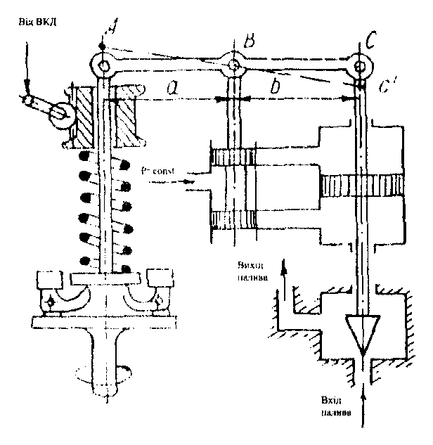
Fig. 3 Indirect action governor with rigid feedback

Fig. 4 Indirect action governor with flexible (isodromic) feedback
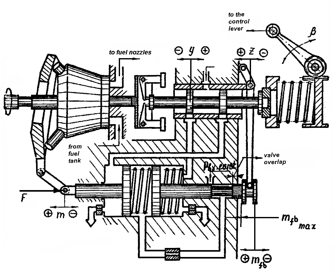
САК частотою обертання газотурбінної установки ГТК-10-4:
1 – корпус регулятора; 2 – втулка; 3 – золотник; 4 – шток; 5 – пружина; 6 – поршень; 7 – імпеллер; 8 –жиклер; 9 – керуючий золотник; 10 – втулка; 11 – мембрана золотника; 12 – пружина золотника; 13 – пружина клапана; 14 – регулювальний клапан; 15 – мембрана СМ регулювального клапана; рм.і тиск масла за імпеллером; рпов – тиск повітря в лінії постійного тиску; рпр – тиск повітря в проточній лінії; –––– – лінія постійного тиску повітря; –- –- –- – проточна лінія

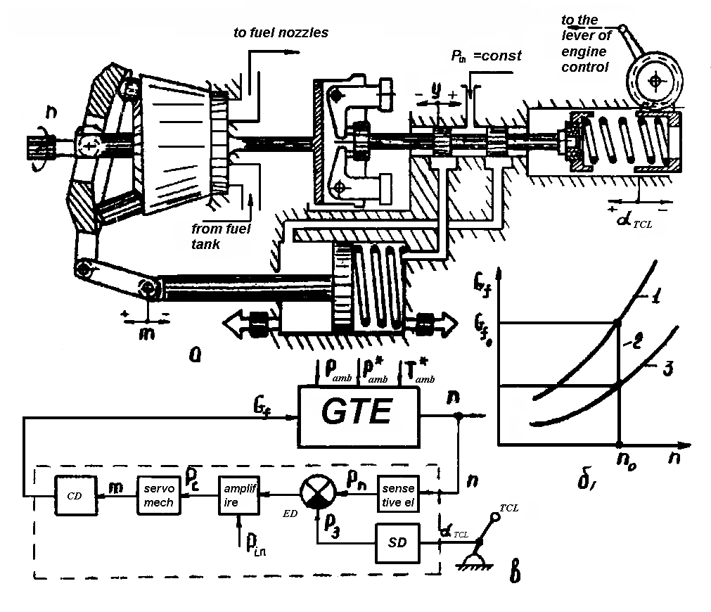
Рис. 6.3. Принципова схема регулятора постійної подачі палива непрямої дії:
1, 6 – жиклер; 2, 5 – пружина; 3 – золотник; 4 – поршень сервомеханізму; 7 – похила шайба; 8 – плунжерна помпа; рн – тиск палива після помпи; ркт – керуючий тиск; – кут установки похилої шайби; m – координата похилої шайби
Possible Control Laws of GTP with double-spool compressor and free power turbine
|
|
а |
б
|
|
|
в |
г |


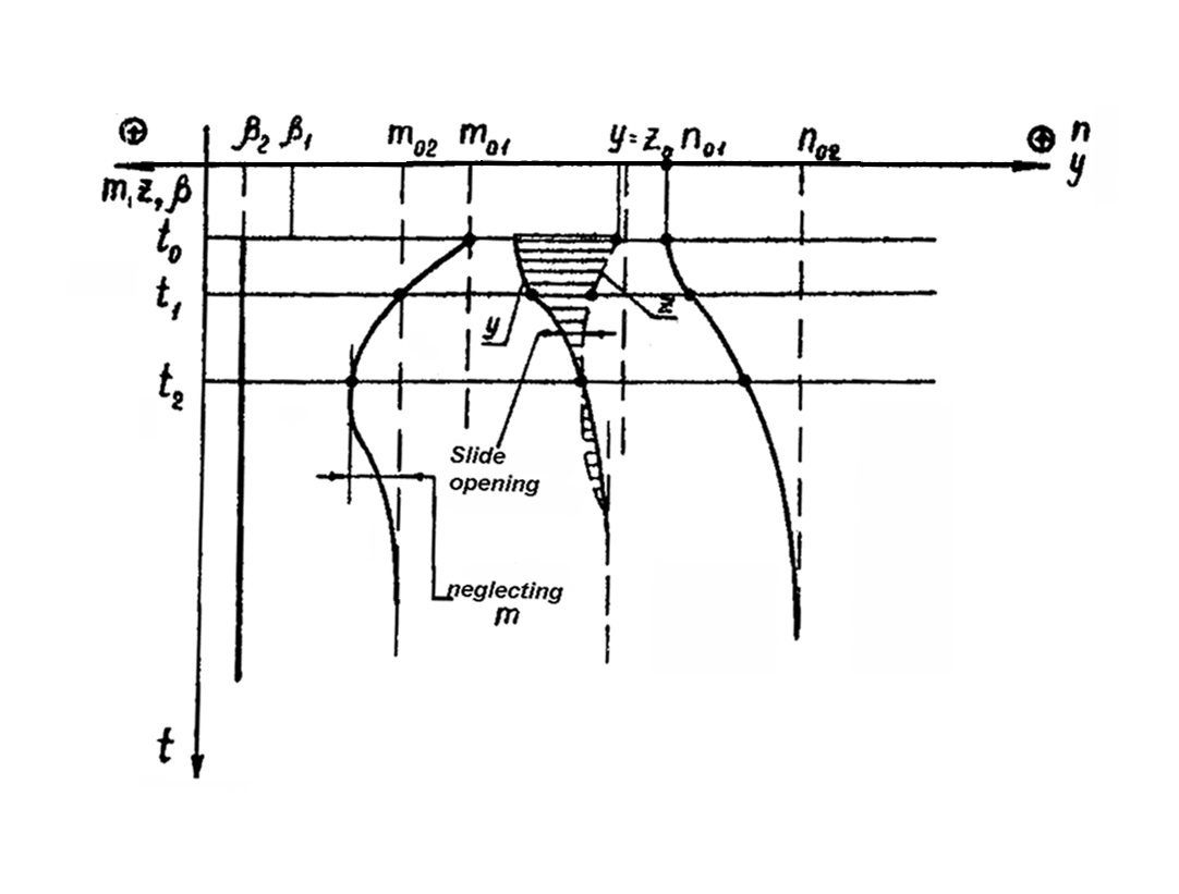
Variation of basic parameters of gtp operation process
under different control lows (CL)
а – nLP max = const; (1)
б – n HP max = const; (2) в – Т*g max = const; (3)
г – nPT max = const (4)
If the condition (4) is fulfilled then control law is given by system of equation (3.9):

 nPT
=
nPT
max
=
const;
nPT
=
nPT
max
=
const;


 n
HP
<
or =
n
HP
lim;
(3.9)
n
HP
<
or =
n
HP
lim;
(3.9)
n LP < or = nLP lim.;
 Т*g
<
or
=
Т*g
lim.,
Т*g
<
or
=
Т*g
lim.,
Where symbol “lim”means that value of the parameter is limited by some way.
So to perform control law (3.9) automatic control system of GTE must comprise beside power turbine speed regulator ( governor) three limiters : low pressure rotor maximal speed limiter, high pressure rotor maximal speed limiter and gas turbine maximal temperature limiter (рис. 3.8).

Fig . 3.8. Block diagram of GTP ACS which operates
under control law according equation system (3.9)

Рис. 7.4. Принципова схема спільної дії голки дозатора газу та обмежувача nст:
1 – відцентровий датчик; 2 – важіль; 3, 8 – пружина;
4 – регулювальний гвинт; 5 – клапан; 6 – сильфон; 7 – голка дозатора

Рис. 7.2. Узагальнені функціональні схеми незамкнутої (а), замкненої (б) і комбінованої (в)
автоматичних систем обмежування некерованих параметрів:
АКП – автоматичний керуючий пристрій; МК – механізм керування