

6 Physical Testing of the Chassis
The chassis supplied by Luego was tested on a torsion rig to determine its torsional stiffness.
The suspension planned for the chassis is of the coil-spring over damper variety. This implies all loads will be applied through these mounting points. The coil-over mounts were therefore used for the constraints and load.
An object always has six equations of equilibrium, three force equations and three moment equations. In order to achieve a statically determinate system, six forces must then be applied. As can be seen in Fig.24 this was accomplished by restraining three of the coil over suspension mounts of the chassis and applying a load to the free suspension mount. If more than six restraints are employed the structure becomes statically indeterminate making the chassis appear stiffer than it is. The deflection was measured along the length of the chassis on both sides with dial test indicators and the global torsional stiffness calculated as described in chapter 4.

Fig. 24
Many torsion figures claimed by manufacturers for vehicles are arrived at while using torsion rigs with seven or more restraints causing the over constraint as described above, i.e. the chassis is fully restrained on both rear corners and at one front corner.
Fig. 25 shows the left rear restraint. The restraint is mounted to the chassis suspension mounting points with ball joints to prevent any moments being applied. The gaps between the ball joints and the suspension mounts are filled with spacers to prevent movement.
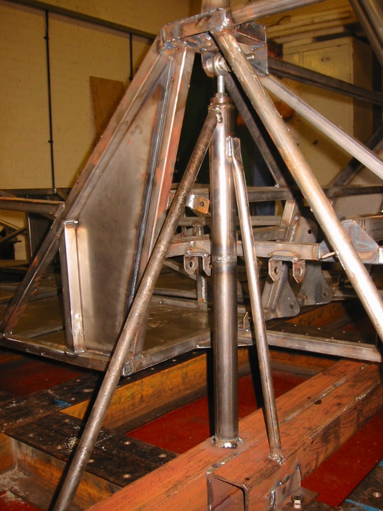
Fig.25
The load was measured with a Horseshoe Dynamometer as shown in Fig. 26 and applied with a turnbuckle. The chassis was preloaded with the turnbuckle before any load and deflection measurements were taken to take up any slack in the rig.
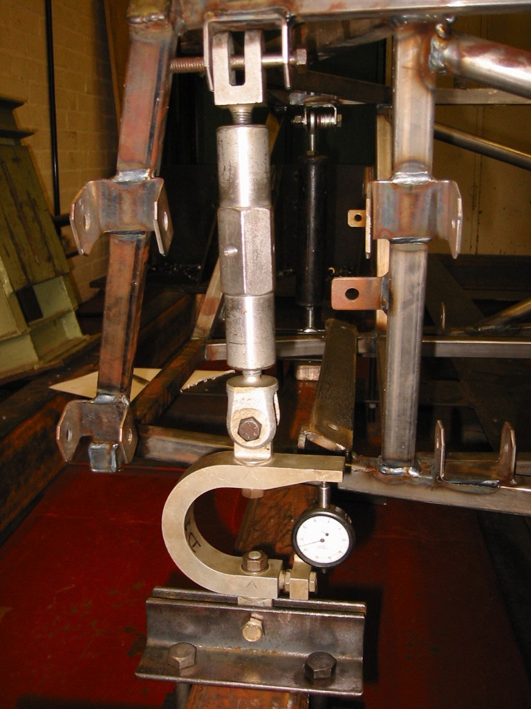
Fig. 26
Fig. 27 shows the deflection measurement points on the chassis.

Fig. 27 Dial Test Indicator measurement positions
1 – Front left suspension mount
2 – Front right suspension mount
3 – Left footwell bulkhead
4 – Right footwell bulkhead
5 – Left mid-passenger compartment
6 – Right mid-passenger compartment
7 – Left rear suspension mount
8 – Right rear suspension mount
From the measurements the Global torsional stiffness K = 1330 Nm/Deg
Fe Modelling Description and Validation of Baseline Model
7.1 Fe Model
To begin the Finite Element analysis a model of the chassis must be created. This was achieved using the universities Patran/Nastran FE modeller/solver software. It was decided to create a line model of the prototype chassis. This type of model is not a dimensionally or geometrically perfect copy of the prototype but a simple representation of it. This was chosen to facilitate relatively simple modification of the baseline model for the improvement study. The results are not intended to be 100% accurate but are intended to give an indication of the stiffness achievable and the effects each of the modifications has.