


In the system changing of one parameter changes the properties of many of the functional elements.
This is system property!

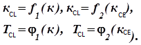
If
![]() then
then
![]() .
.
Coclusion:
Correcting
elements influence. Increase of
![]() leads to a decrease in
leads to a decrease in
![]() as compared with
as compared with and a decrease in
![]() as compared with
as compared with
 .
.
Ways to reduce the transient time or increasing of swiftness.
1)

2)
![]()
So the ASS transient characteristic performance and set its value can be achieved a number of ways.
construct
graphs of
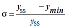
overshoot – direct indicator of the quality characteristing the extent of removal from the vibrational stability boundary, i.e. stability margin of the system. In general, the ASS response to a step disturbance can be represented as:
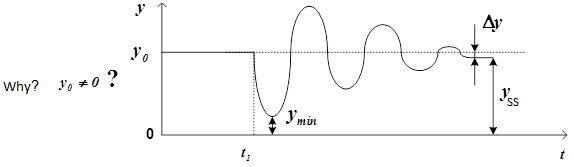
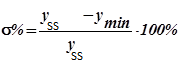
Overshoot is calculated by the following formula
 or at such
nondimensional quantity
 –
corresponds to
the minimum value of the step response, and
–
corresponds to
the minimum value of the step response, and
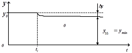
![]() – corresponds to the steady state value of the step response.When
the step response has aperiodic nature overshoot
– corresponds to the steady state value of the step response.When
the step response has aperiodic nature overshoot
 .
There are stabilization systems for which overshoot is not
permissible in general.
.
There are stabilization systems for which overshoot is not
permissible in general.
The number of
oscillations –
 of
transition function relative
of
transition function relative
![]() or
is an additional feature of the ASS stability margin.for some classes
of ASS,such as the stabilization systems of the aircraft, the
fluctuations are not permissible. n=3!
or
is an additional feature of the ASS stability margin.for some classes
of ASS,such as the stabilization systems of the aircraft, the
fluctuations are not permissible. n=3!
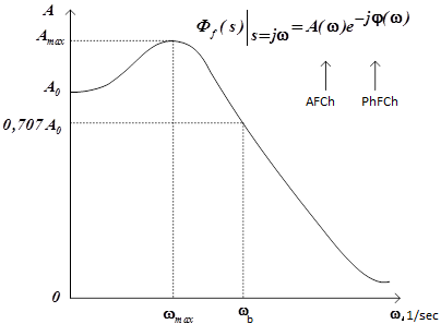
Bandwith – indirect index of the quality that characterizes the swiftness of ASS. The wider the bandwith,the faster the system.Bandwith is characterized by the value
 and calculated by frequency response function of system at the level
 .
To estimate the decay time of the transition process such
approximate formula as used
.
To estimate the decay time of the transition process such
approximate formula as used
![]()
Bandwith affects on the accuracy and speed of the system. The higher the bandwith, the greater the range of the input signal passes trough the system without distortion. Therefore, the accuracy of the input signal processing rises.
5.Index
of oscillation –
indirect measure of the stability margin of ASS.Index of oscillation
–
 is defined as
 .
.
usually
 .
For small M system is "
sluggish "
and has a long transition process and, consequently, a high stability
margin. With large M overshoot increases and the system approaches to
the stability boundary.
.
For small M system is "
sluggish "
and has a long transition process and, consequently, a high stability
margin. With large M overshoot increases and the system approaches to
the stability boundary.
AXIOM Montaigne |
: |
Bookish Lerning – decoration, but not foundation |
Topic №2: A typical configuration of the controller(regulator)
Рл

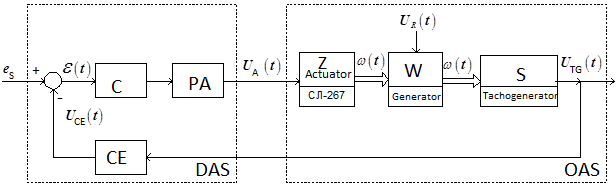
Consider the functional diagram of laboratory ASS of angular velocity of the working mechanism.
Controller (C) - one of the possible solutions of the stability problem and providing of the closed loop ASS quality.
Problems of stability and quality of closed loop ASS most effectively are solving in the class of linear control systems, i.е. systems described by the linearized mathematical models in the form of linear differential equations with constant coefficients, and in the form of transfer functions.
Let’s us present laboratory ASS of angular velocity of the working mechanism with the block diagram of the form:
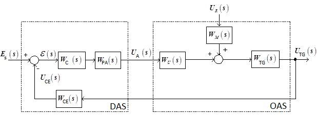
here
![]() – C transfer function;
– C transfer function;
![]() –PA transfer function;
–PA transfer function;
![]() –CE transfer
function;
–CE transfer
function;
![]() – Image of setting action;
– image of error;
– Image of setting action;
– image of error;
![]() – Image of control action
– Image of control action
![]() ;
;
 – image of disturbance
 ;
;
![]() – Image of tachogenerator voltage;
– Image of tachogenerator voltage;
![]() – Image of correcting element voltage.
– Image of correcting element voltage.
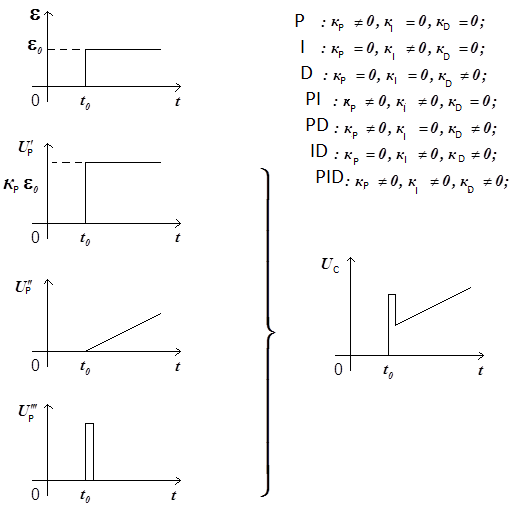
In recent years,in the theory and practice of automatic control the proportional-integral-derivative (PID) structure of controller (C) – was widely used.Functional diagram of a generalized PID regulator has the form
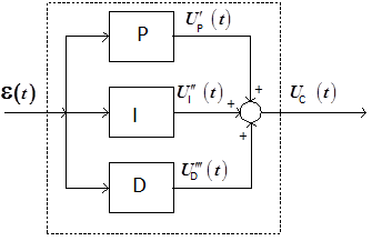
Here
 – deviation,
![]() ;
;
![]() – output voltage of C,
;
– output voltage of C,
;
![]() – proportional element;
– proportional element;
![]() – integrating element;
– integrating element;
![]() –
differentiating element.
–
differentiating element.
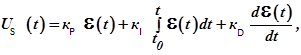
In the linear approximation, the components of regulator can be described by these equations:

In general regulator is described by the following:
Where
![]() and
and
![]() – appropriate transient coefficients.
– appropriate transient coefficients.
Functional features PID regulator look at the step response
Applying to both sides of the integro-differential equation of PID regulator Laplace transform, we obtain
![]()
A detailed block diagram will look like this
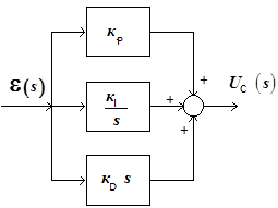
Then the transfer function of the PID regulator will be like

Now controller can be an
element of the block diagram SAS
So , the PID regulator contributes to open-loop transfer function of a single pole located at the origin of the complex plane of the roots, and two zeros, which can be placed anywhere in the left half plane.
We define the transfer
function of a closed loop laboratory ASS on error from the
disturbance. Recall that
Taking into account such terms:
and substituting them into the expression of a closed transfer function, after appropriate transformations, we obtain
Using the final value theorem, we define the steady state value of the error
The characteristic
polynomial of the transfer function
Selecting the desired
poles we can determine the location of the roots and unknown values
 and
and
 to provide the stability of the closed loop system.
Please give an example of the desired location of the roots.
Achieving quality will clarify values и .
K.F. Teodorchik, E.G. Uderman-Root locus method