

Pure over-unity extraction circuit
Back round.
About the RV rotor being pushed by the magnetic fields on the Aluminum cage in the rotor. There isn’t just a push but also there is a pull. This is because of the steel laminates that are impregnated also. So then I [Phil] realized where this mass of energy that builds up in the motor comes from. It is our classic Seebeck and Peltier effect happening inside the rotor. At the junctions of each different metal there is high currents generated which intern form a powerful magnetic field in the rotor that acts in the opposite polarity too also act on the field windings. It is so obvious now what is going on and how it will be so simple too collapse the wattage input down too nothing. This is related about the Aluminum in a generator rotor and where shown is what the 2 metals will do in a magnetic field, with the push and pull. It’s already being done in the 3phase motor.
The Seebeck and Peltier effect are the wonderful things that happen in the squirrel cage. They run steel and Aluminum together too generate the currents from the magnetic fields and temperature differentials.
It’s a work of art you get a push and pull effect from these metals from the coils too give greater torque.
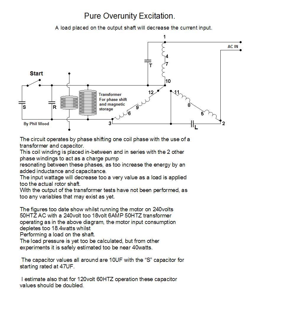
What we do with this extraction circuit is generate a new harmonic in the windings that charge pump too a higher level and then we just load the shaft. I realized this when I [Phil] loaded the shaft a few weeks back and the wattage input dropped. Just by generating a new frequency riding on the mains frequency a new value comes in where the internal pumped around energy multiplies, and then you can do real work with no added wattage input.
A.R.S.C (auto resonance switching circuit).
The Auto Resonance Switching Circuit (ARSC) operates by tapping into any resonance coil or motor winding where a load is connected in series with a capacitor. Once the capacitor is at a fully charged state the Mosfet auto triggers and dumps some of the charge back across the load. The monitoring circuit reads the voltage of the capacitor and will not allow the capacitor too fully discharge, thus keeping the voltage where it is past the main current phase shift. Another function of the monitoring circuit, is too not allow the capacitor too partly discharge while there is a potential charge taking place from the resonance side. A more detailed description is understood where, as a positive voltage is shunted through diode A and pushes against the load resistance thus charging capacitor B. If the voltage in capacitor B has not reached its fully charged state the switching circuit remains idle until the voltage threshold of the capacitor is reached. This is detected by the voltage monitoring circuit C. With each continuing voltage shunt through diode A, the load is powered with respect too the capacitor B being charged.
When the voltage detection circuit C triggers the CMOS input pins it is known that capacitor B is fully charged. The secondary voltage monitoring circuit E activates the CMOS input pins only when there is no positive potential at diode A. By using NAND and NOR gate functions with the CMOS chip and the 2 voltage detection circuits, the CMOS chip activates the Mosfet driver too a high state when capacitor B is fully charged and the diode A is at a low state thus turning on the mosfet.
![]() As
the mosfet D is activated capacitor B is partly discharged across the
As
the mosfet D is activated capacitor B is partly discharged across the
![]() load
thus powering the load once again. If either voltage monitoring
circuits change there state the mosfet is instantly switched off by
the combination of the CMOS configuration.
With the said
circuit operation, very little load is applied too the resonance coil
as the capacitor is kept past its initial current phase shift, but
there is a current discharge across the load at the correct
voltage
and time intervals.
load
thus powering the load once again. If either voltage monitoring
circuits change there state the mosfet is instantly switched off by
the combination of the CMOS configuration.
With the said
circuit operation, very little load is applied too the resonance coil
as the capacitor is kept past its initial current phase shift, but
there is a current discharge across the load at the correct
voltage
and time intervals.
For driving a DC load, a bridge rectifier is placed where the load is shown connected, and then the DC load is connected too the other rectifier terminals. For optimizing the circuit operation, it is beneficial too know the expected voltage that will be operating on the resonance coil and use the appropriate components.
As an example: if the voltage expected is 100volts across the resonance coil the capacitor B voltage rating should be close too 120volts. The Zener diode used for detecting the capacitor voltage should be rated at 80volts thus the circuit will keep the capacitor above a 2/3 charged sate being past its current phase shift resistance. By Phillip Wood.
Laymen’s by PHIL
With the circuit, you are taking off voltage potential from the resonance side and not current. So the 4AMP power diode is actually not handling much current at all, but it’s the mosfet that belts the voltage build up from the cap into the load. So it is actually the mosfet that has too handle the current more than anything. When a capacitor is being charged the first time it takes current too get things going. But once it gets like past half way it fills up with little current but basically just voltage. It is all linear, but this explanation is breaking it down for you the reader. Now when we discharge the cap its pure current that is hit across our load, but we make sure we don’t discharge the cap much at all so it fills back up with just voltage for the next hit. There are issues when going into high voltage high current mosfets. What happens is the gate voltage to activate them is 30 volts and this means you have to add a pump charge circuit on the board to drive them. Not a real issue one can be drawn and made workable into the circuit. Now the next problem is that these types of mosfets have a slow turn on time and dead time delays. When we are working with these high frequency resonant situations we need a real fast switching mosfet that will work when we tell it too. So in this actual circuit you will need to look for the right type for the requirements as stated in the explanation. We are aiming not too take much current off the resonance side but only voltage and then convert this to current pulses. This is as far as we can push the mosfets of this voltage and current but have enough switching time. 134ns turn on time is about as slow as we could go with high frequency resonance.
Also the current in which any high voltage mosfet can handle is very low and it isn’t what they say on the data sheet. Well it sort of is, but they rate the current at a 10volt load and not at there voltage rating. So we should be able too switch around 400watts with the one mentioned below.

For those looking to push higher threshold voltages and or make the circuit more ‘bullet proof’.
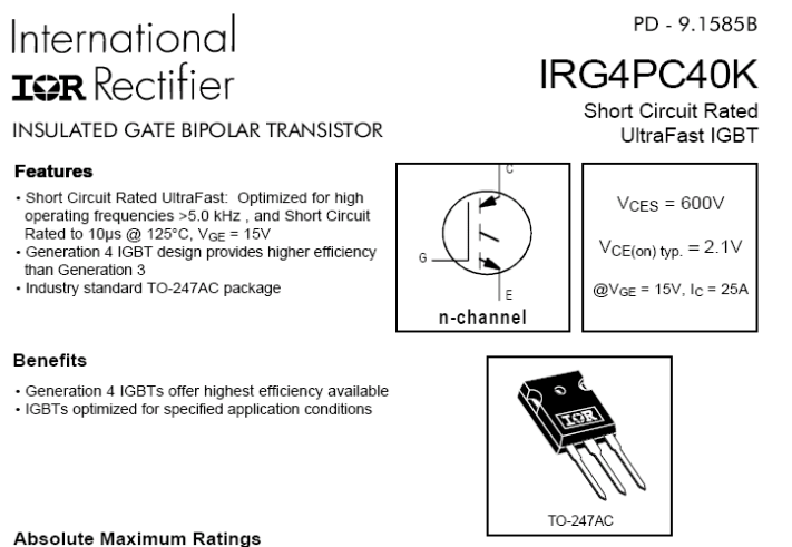
Phil has just found an IGBT FET that will do the trick (mentioned below). It's got all the right numbers. It also saves mucking around with a pump charge driver circuit as this one for some strange reason has a nice low 20v gate voltage. With the circuit I think it is best you run a switch bank of different Zener values so you can select the voltage trigger levels for when the PM (RV prime mover) is running right. It won’t surge and ounce with this circuit, but it is just having a rough idea of the operating voltage on the resonance side. I would have say 200volt then 250volt then 300volt selections and then just let the circuit do the rest.

ARSC circuit is just learning the basics.
You can, and will get full O-U with just electronics where no magnetism is involved. It is simple and easy when one just takes note of all the boundaries involved with electronic components. The energy increase does come from using coils but it also involves understanding capacitor behaviors and the BEMF that actually comes from a battery. A battery is also a component with capacitance and resistance but also has an inductance behavior.
Referring to a sealed led acid battery, there can be seen voltage spikes when the battery is subjected too sudden pulsing. Also a battery has the same behavior as and inductive coil where it uses very little current when low on capacity and the current consumption rises as it begins its charge cycle. As the battery develops its full capacity it begins too sharply open up a greater resistance. From my many years of working with DC circuits I [Phil] have found that battery charge levels are also a very important factor in O-U operation.
We discovered this when the BECS circuit( Phil’s wheel patent) was being 3rd party tested where it was monitored with computer software, and when the battery internal resistance became the lowest the DC motor under heavy load maintained a constant drive returning all energy back too the batteries while the RPM was close to being twice the original speed.
The motor maintained this RPM for 2 hours while the identical motor and batteries running along side the BECS had run down 1 hour and 45 minutes before hand. In summary, once the batteries feeding the BECS began too slowly discharge and a greater resistance developed across the batteries the motor began too quickly drop in RPM until all things shut down.
The secret operation of the BECS was too use 2 batteries where one would charge while one would discharge and vice versa, but all BEMF was phase shifted by being dumped into another resonance coil where its bounce back re-powered the load in series with the battery being charged.
In conclusion, I perform all tests on my circuits through the full range of a charged battery until considered flat. It will be seen as with the ASRC that during the battery cycle there will be a long time period of extra load performance and much higher energy gains once the battery is at its lowest resistance.
As with my tests running the 3phase motor in RV mode and using the ACR inverter circuit, being powered by 2 X 4 AMPH batteries there was a run time of 2.2 hours on these small capacity batteries.
Quote: For every action there is an equal and opposite reaction.
Everyone will have there own points of view but mostly there own focus on how the energy gains should be achieved. Hectors resonance concepts are important and is a must for power savings. My focus has been by using auto resonance tuning and known scientific capacitor behaviors.
The ultimate system is the RV controlled by an auto resonance tuning AC inverter with a battery parallel and series charge circuitry. This way any subjected loads too the RV will be auto adjusted for the ultimate performance and all energy returned too the original sources. Using step up transformers this is easily monitored on the low voltage primary side and will auto tune out any variables