

Dc Permanent magnet rv rotor.
Quote:
The answer is simple, in a PM generator Logarithmically charge a CAPACITOR to joule potential under half resonant diode rectified state (as trans-verter plug does ).
-end quote
The DCPMRV rotor –DC permanent magnet rotor run in RV mode is superior efficient running motor design. The PM RV rotor eliminates the motors slip loss in the RV generator side therefore increases the efficiency to 100% . A slip is a poor design that squirrel cage motors (currently used as RV ‘hosts’) are designed with. Doug konzan has already modified a 5hp 3PH motor and eliminated the loss of the slip via this modification. Important core drag issues are still on the R and D table with this method, but it is workable. What is needed is a PM rotor designed as to be magnetized to near saturation point but not exceeding the CORE saturation as to have minimal on NO saturation drag effect.
Kone has since stated -the 5hp I converted you mention with ugly stainless tell fishing line and JB weld holding in big neos strapped to old 5hp rotor is actually running on DC and is too heavy and ugly and I plan I taking it apart for parts soon. so anyways I wouldn’t mention that I did the PMRV thing to a 5hp AC motor since I did, but not worth mentioning! There is a 1/3hp AC motor I convert to a PM rotor, its
more better PMRV construction seen on site: www.geocities.com/koneheadx/
However "AXIAL" AC-run PM-RVs are easy to make (such as 2pole n-s rotor with 3 120degree spaced stator coils) OR: did you know even basic ADAMS All-N rotor magnet PM design will work in AC (!!) (such as Bedini schoolgirl monopole motor as simple example)
Just space evenly the magnets in the rotor,(pre-plan it) so that the pull-push of the AC frequency you are dealing with pumped into its motor coil will synch-up at that certain RPM(to attain) – this synchromesh AC event will coincide with the pull-and-pull rotor power-"points" in rotation of the magnets you are using in rotor...(coil to pull before coil lines up "straight" to rotor-magnet, then coil to push after it lines up straight)
I found that almost always, you want that magnet to be halfway across the coil to push, (or pull it too) the rotor around with strongest power "point" in any PM rotor.... AC is just alternating DC "pulses" so whatever can be done with small classroom-size motors like the Bedini monopole chassis, can be done in AC too...(motor coils align to pull before magnet, push after magnet...line up so magnet will be half way across either pull or push
- Nutshell description summary
There...its always good to space magnets in a rotor the same distance apart (edge to edge) as the magnet overall width...(AC will work as well then).
In PM design Raivo has added the basic rotor design CAD to Dans RE-OU 5.1 compilation. 3600RPM =2 rotor poles N,S 1800 =4 poles
The RV driven PM generator is also a research and development method to quantify the issues in the reverse dynamometer capability of RV.
Using a PM RV and 3PH pulsing & recovery is the way to go and it seems the reason to ELIMINATE synchronous motors was to get rid of OU manufacturing Devices. Info:http://www.tpub.com/content/neets/14177/css/14177_101.htm

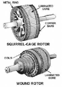
4-17 THREE-PHASE ROTATING FIELDS require three pairs of windings 120º apart, energized by voltages that also have a 120-degree phase displacement. SYNCHRONOUS MOTORS are specifically designed to maintain constant speed, with the rotor synchronous to the rotating field. Synchronous motors require modification (such as squirrel-cage windings) to be self-starting. Since Synchronous PM motors are hard to get my choice might be a 120/230/460 20KW generator Brush - Basler exited type. Eliminate the exciter unit and Use a DC variable power supply as to control rotor Magnetics. 120AC to 0-120VDC Generator Wired to 460VAC Use standard RV to rotate to speed then switch to power line As rotor is magnetized Unit will generate KVARS into System A Current regulated exciter might be used to control KVAR production. As POWER FACTOR is corrected your power bill will be reduced 40% or more. Why pulse it ? with DC.. Power factor correcting the battery ? (I read that some were ) if Battery is taken as a capacitor and load as L (n) given impedance then we can assume an standing wave is developed in Voltage Amperage relation where a delta T transform will occur where a battery pole will cool down and the other will heat up Being the Discharge 1 half cycle, only theory explaining why splitting the positive works, but in reality is RF power factor PF correction, half sine of it. If such standing wave is REVERSED as in NEWMAN motor the Stepped switching on and off of linear DC will pull THERMAL power from COIL ATOMS transforming heat to electric power by stochastic resonance amplification. The Magnetic Field contributing to the equation as a linear amplifier system. So Doug Konzens HV DC PM Pulse RV indicates a path to go into universal motor development ,TRUE energy transforming Devices. DC/AC Rotor conversion can be request to specific details from http://www.tecowestinghouse.com/Products/Custom_Engineered/synchronous.html
TECO-Westinghouse Motor Company - Custom Engineered Synchronous Motors & Generators
Full Speed Ahead
TECO-Westinghouse Motor Company synchronous motors and generators provide superior value in terms of proven reliability, low maintenance performance and long life in any application. Our synchronous machines offer numerous benefits including:
Constant-speed operation
High efficiency ratings
Low inrush currents
Leading power factor (for corrective KVA capability)
These features make them the optimal choice for many industrial drive applications.
Power factor improvement is one of the most attractive considerations in selecting a synchronous machine. Synchronous motors operate at leading power factors and are available with rated power factors ranging from unity to leading. Thus they can produce substantial savings by supplying kvar’s to counteract lagging power caused by other inductive loads.
» Request a Quote for a custom engineered product.
Read and WAKE up as a great Truth is being POSTED here that If you Attract a GREATER force with SMALLER ONE the Greater will amplify the smaller one The WORD LEADING implies POWER PRODUCTION ,OU due to magnetic amplification the so called POWER factor Correction is the answer to OU transform "KVARS". You Supply a greater magnetic Field to a Synchronous motor rotor it will produce more power than it consumes LEADING POWER FACTOR...... (Secret OU terminology)
Thoughts by Raivo
PM RV is very interesting, especially when you couple it with some efficient DC generator as Kone did. The small problem that Kone has is that he can create much better results when the impedances are matched. I mean - DC alternator speed/output/VA must be matched to the right capacitor. Or the input RV must be run at higher frequency to increase eff%. I think there are plenty of room to make it more efficient
PM RV must be wired to 460VAC, the grid must be lower ca 120VAC, but it can be 230VAC 3PH. Motor must develop the resonance, its voltage is bigger and the current flows back to the grid. (as Hector said - oops, it starts to power factor correct the grid as PM RV is naturally OU) I have deciphered those rotating magnetic amplification stuff (almost) and try to explain you in step by step: * as H postulates: resonance has (always) the RE component (was it theoretical 0.382 or .618 depending on situation, Q and parameters) * the second postulate is that in normal resonance the energy reflects back to the grid so it is wrongly understood as some PF correction phenomenon * in a LC resonance using FR transformer this magnetic shunt and resonance recovery will allow the power not to reflect back, so the current in primary will not rise and you tap the excess energy from the secondary keeping the resonance going. Resonance requires only part of energy to sustain. This is the first trick. * in RV (with a single capacitor) - this back-reflection is avoided by 120 deg shift and it is OU. In a sense, it sends some excess power to do mechanical work. * in RV (with many capacitor versions I know, squirrel cage) - this multiplication is allowed to happen many times as well as when tuned to higher harmonics, causing the power meter to go wrong way! (requires tuning with load) * in PM RV multiphase resonance (a la PF corrector synchronous motor) - you have the device that is in high impedance mode. Line must be lower than motor wiring. 3PH configuration in caps allows it to roll the VxA many times in amplified mode until it rotates the phase that feeds the grid back. Yes, its strange, you'll have the negative average energy balance. (you may tune it with the load as well). When you run it from the inverter the system should "PF correct the battery". * this way to the next levels to the hyper efficiencies and high power H would say in other words. I may have expressed some parts not well (or my memory may fail in details), but the all the practical key points are said here.
The main idea is to keep the rotational energy in the circulation to put it to make work in a squirrel cage (or PM RV). Higher harmonics allow 2 things as I understand: higher freq - better amplification and also pushing up speed. It is not clearly understood what takes place. Again I repeat that the motor must be tuned with the load as the effect will be created at the certain impedance unless you're lucky to match the right caps at once. Prony break or better - a coupled generator becomes handy. (what I tell ya is not what I did, but I know from some sources what is possible). Kone (in Finnish Kone means motor!) may test as well many capacitor connections on phases, changing phase polarities, it will not like to start in many cases so you need to get it up to speed with some tricks. There is the holy grail hidden in there. The best setup to try this project is: 3-5HP RV coupled to the alternator and also belt coupled to some starter motor .-end
The PMRV is related to the concepts of RESONANCE hyper Q states , logarithmic and the magnetic amplification factor in LCs. Easy transferable to RV in a low voltage hi impedance rotary pulsed machine. With a PM RV design pulse driven with logarithmic power and CEMF recovery in a full phases diode bridge. 3x3 configured or (n X n). n being number of phases used as in a multiphase PM genemotor concept.
All that is required an standard 230/460 3 phase motor with a PM rotor designed as to be magnetized to near saturation point but not exceeding the core saturation as to have minimal on a NO saturation drag effect. Secret is tuning into the resonant states and optimizing use of the power attained without killing the OU LC effect.
As In a Stator the PM rotor within a given impedance makes this resistor negative as the VOLTAGE drop in the line is minor than the voltage drop in virtual LC resistor, as the generator works in Synchronous HI impedance Rotary condenser mode.
This Results In Electro Magnetic Amplification were H=(IXI)Rt EMA. Were APARENT power Contributes to SOURCE POWER on OTHER mode of RESONANCE taken to a POWER factor corrected NUL , ZERO POINT energy state VAR production in HI virtual OU impedance Value.
Reference formulas. http://www.nepsi.com/formulas.htm
THE M field is your POWER SOURCE when you create a SELF amplifying amplitron RV PM Alternator. FACT is ANY HI eff GENERATOR wired to 460VAC and run synchronous in 120VAC can be used to make and demonstrate this principle. Once understood a PM generator is WIRED as to create these effects .This is Instant Applications in Energy savings now possible From SOLAR cogeneration to motive power as the formulas and explained BASIC theory justifies. The logical next step with the R and D from the RV is to apply it to the PM driven Coils.
In this configuration the LC is seen as a RESISTOR and as Such you READ AMPERAGE and Multiply by the VOLTAGE SOURCE and GET ITS VOLTAGE drop VALUE (Basic Ohms law ) named AKA - Voltage drop. As the VOLTAGE drop in the line is more minor than voltage drop in virtual LC resistor that means the virtual RESISTOR possesses ENERGY transferred from attracted M field to attracting M field. IN IMPEDANCE MATCHING ITS CURRENT MUST BE EQUAL. Even if RESISTANCE is unequal Voltage and Resistance are the determining variables to MATCH virtual resistors and reverse energy to source were then Current REVERSES being of a lager magnitude than the source. As the LC voltage is INDUCED it attracts the ROTOR magnet so M1 attracting magnetic field attracts M2 summing and exceeding M1 turning the VIRTUAL Unity resistor to a NEGATIVE over unity resistor as its ENERGY LEVEL is more than the one supplying it (Source) . That means Current at a given POINT reverses to SOURCE supporting ENERGY to it usually in VARS as Power factor and cogeneration Laws apply.