

Ecklin Brown design
Quote-The real issue is going to magnetic interrupt with the proper Core design the Ecklin brown data is the right path, MAGNETIC interrupt, the idea is to saturate a core at collapse were there in no lenz component and Extract it in OU level .-hector –end quote.


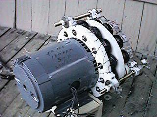
Above is a prime mover
wired for RV (courtesy of ED) mode coupled to an ecklin generator
under construction. Hector has his own design of an enhanced version
of the ecklin generator tailored for the RV.

Statutory Public copyright (Other Rights Apply) local and international. (Publication) Scientific discovery, Roto conversion Effect and ARK ecklin design covered by the publication statutory copyrights for 75 years. This is hector personal design.
Muller design
Doug konzen has been the first to apply the RV Prime mover to a Muller generator for over unity (higher efficiency) design.
Doug (recovery master) has since perfected a shorting of coils recovery concept.

Quote:
SHORTING coils out with switching too.
MY power-testing of coil circuit now is simple FWBR across coil, DC out into cap, resistance always across cap, (not switched resistance) the trick is to SHORT the coil with the reed switch controlled by rotor magnets and adjust timing until volts goes up in cap to maximum (and with resistance always across cap too)
just added all-N 16 small timing magnets to trip the reed switch in the rotor now, so the timing of reed switch closing and opening will be in "same polarity" since rotor is N-S magnets and this keeps motor from going up in draw except minimal)
It is obvious big boost in power output of generator coil when you add the reed switch shorting-coil circuit, as example, from normally 18VDC without switching (and no resistance), now you see 150V in a second or two in the cap if you have no resistance, and 280V if you let it climb for awhile.
The motor doesn’t go up in draw except for around 1.2 watts during this test - that’s equivalent to .01 amps extra draw (X 120Vac) Using ohms law to find current, (calculated while knowing voltage and resistance while in DC) that’s this:
with reed switch shorting coil:
12.4VDC / 30ohms = .413amps X 12.4VDC = 5.12watts
Compared to without switching:
8.2VDC / 30ohms .273amps X 8.2VDC = 2.23watts
Standard brush generator design
For R&D purposes you can use off-the-shelve gas/bensin generator attached to a RV prime mover - just remove the engine and leave the generator. Add RV prime mover and adjust to 3000RPM or experiment. This generator is wise, it regulates 400VAC automatically by DC excitement. The generator is good as it is off-the-shelve, it is standard, it can stand high RPM (hopefully low eddy current losses) - all should be tested with RV.
R and D goals
* first, testing running without load (to determine friction, bearings) * comparing the AC input from RV and output 3PH rectified to DC, loaded, we get more ideas. DC output is good as there is no switching; the output is pure sine wave from standard generator and will eliminate measurement errors.
* altering the exciting DC (there is usually 12V battery on board to automatically provide excite current, do it manually) and testing output on various DC loads - standard generators should enter into OU range (as well shown on WWW and documented) * and advanced test - power factor correction using RV style exciting – (advanced, but very cool,) Conclusion: it is a relatively low budget thing, buy a cheap generator 2-5HP, remove the gas motor and attach to RV prime mover. The generator would be good to have 1 and 3 phase outputs, some generators have also 12V outputs for battery charging.
Generator modification for OU efficiency.
Taken from
http://www.harborfreight.com/cpi/ctaf/Displayitem.taf?itemnumber=45416
10,000 WATTS PEAK/7200 WATTS RATED BELT-DRIVEN GENERATOR HEAD
|
|

Build your own belt driven brushless generator 3600 RPM Uses a 20 HP gas or diesel engine for maximum performance Comes with two 20 amp 120 volt receptacles and one 30 amp 120/240 volt twist lock receptacle Circuit breaker protected 92 lb. shipping weight Keyway: 1/4''; Shaft: 1'' diameter x 2-1/4'' long; Belt driven
This GENERATOR uses REVERSE induction winding as stated in posting dating since the disclosure of the Bingo motor ((brown gas project in JLN yahoo groups)
Instructions- obtain this designed generator and modify
1)remove fans and all drag making junk 2)remove capacitor from exiting coil 3)excite main 220 coil using oil capacitors
4)measure power in against power in LC there is your OU to work with. 5)Use A PM (permanent magnet) rotor with no over saturation of metal cores as in ANY existent HI eff motor, logarithmically load power to C you and have extracted the OU efficiency. Eliminating the Exiting capacitor from exciter winding and Using a CAPACITOR on its BASIC OUTPUT WINDING to achieve RESONANCE state produces RADIANT ENERGY in well beyond an OU region.
Applicable to SERIES tuned LCR electrolytic chamber , in CAR alternator using 23K to 24.5KCPS sono- fusion (see RE-OU-5.1 e-book) can be attained in electrolytic chambers by using the same LCR RV and trans-verter RESONANCE principle.
In this cheap harbor freight ALTERNATOR using the main winding as an LC oscillation with oil AC capacitors suffices to create the radiant AC power at a 0 power factor. Further then it is required to take amperes to match a filament light bulb where by the voltage drop becomes minimal and can be lit under water exactly as seen in EV Gray demo.The RV principles are to Learn to transform adapt and use this energy , to learn to optimize power management .and definitively looping will come by default
Hectors non profit agenda is to start in power savings, teach power management as with the existing waste engineered into the existing hardware no OU can survive at the user end. For that the R&D tools and items must be made available. This is where grants are essential as there is much more to be improved on and R&D.