

Inductive trigger’s advantages over the opto-trigger are: no false triggers due to lower
sensitivity, lower power consumption and simplicity.
Collecting/extracting the power from the resonance
While one capacitor is sensed and triggered the other is discharged. Normal LC resonance is preserved and other capacitor behind diodes are smaller that the main capacitor, this way we will tap only certain proportion of the resonance. A partial power extraction is required where we need some charge to be left in a main capacitor that will preserve the magnetization of the alternator (RV alternator)..

EASER array
Or you can create an impulse where the collapsing EMF or CEMF or BEMF is caught into the capacitor (and then switched to load).
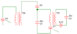
The circuit ends with the capacitor. It can have the next stage in the array where similar SCR trigger mechanism is used to discharge other polarity capacitor to the next stage and so on until the load stage. You may call it a Resonance Collection Array using Diode Plug (RCA Plug).
Notes
As per ‚book’ we know the array uses EASER principle for power amplification where each stage has its own required parameters. To create the required condition, Hector has recommended the optimum transformer ratio to be 1:5 and the capacitor ratio 2:1. Another note is that the voltage must be quite high to have better efficiency and the primary to have minimum number of turns and big wire that creates shorter impulse. A simple SCR diode plug extractor implementing HV-RC to test the SCR switching
efficiency from the normal grid should be implemented first! The next step is to use this circuit to tap the resonant power of the ferro resonant transformer. Alternatively, when switching power through out the transformer, the Xenon trigger can be used for R&D purposes instead of SCR’s to create very sharp dis -charging that cause many interesting effects.
The advantages of this array are:
• it will amplify AC and output AC
• simplicity, ‚a spartan’ design
• it keeps the freq in sync to the output
• array as the name tells – it is cascadable
• high voltage design and practical use for Roto Verter alternator or trans verter resonant
power extraction • you can run a RV prime mover with those impulses or resonate a 3PH transformer
(ideas for the future)
Resonance collection ideas by Raivo
Resonance collection ideas
2006-10-22

Figure 1. Original Diode Plug, resonance collection, switching capacitors to load at blank intervalls

Figure 2. Resonance collection with FWBR (sinewave clipping)

Figure 3. Simplified resonance collection

Figure 4. Extra simplified resonance collection
My idea: diode plug can be simplified to FWBR resonance collection, the difference is that
new circuit uses sinewave clipping, but preserves the resonance (fig. 2) where IRF740
switches in the load during sinewave peaks. Going further with this idea – we take off the
switching when we use a proper load to preserve the resonance (fig. 3)? What we can see now