

166 |
|
|
|
|
Broadband Microstrip Antennas |
||||||||||||||||
|
|
|
|
|
|
|
|
|
|
|
|
|
|
|
|
|
|
|
|
|
|
|
|
|
|
|
|
|
|
|
|
|
|
|
|
|
|
|
|
|
|
|
|
|
|
|
|
|
|
|
|
|
|
|
|
|
|
|
|
|
|
|
|
|
|
|
|
|
|
|
|
|
|
|
|
|
|
|
|
|
|
|
|
|
|
|
|
|
|
|
|
|
|
|
|
|
|
|
|
|
|
|
|
|
|
|
|
|
|
|
|
|
|
|
|
|
|
|
|
|
|
|
|
|
|
|
|
|
|
|
|
|
|
|
|
|
|
|
|
|
|
|
|
|
|
|
|
|
|
|
|
|
|
|
|
|
|
|
|
|
|
|
|
|
|
|
|
|
|
|
|
|
|
|
|
|
|
|
|
|
|
|
|
|
|
|
|
|
|
|
|
|
|
|
|
|
|
|
|
|
|
|
|
|
|
|
|
|
|
|
|
|
|
|
|
|
|
|
|
|
|
|
|
|
|
|
|
|
|
|
|
|
|
|
|
|
|
|
|
|
|
|
|
|
|
|
|
|
|
|
|
|
|
|
|
|
|
|
|
|
|
|
|
|
|
|
|
|
|
|
|
|
|
|
|
|
|
|
|
|
|
|
|
|
|
|
|
|
|
|
|
|
|
|
|
|
|
|
|
|
|
|
|
|
|
|
|
|
|
|
|
|
|
|
|
|
|
|
|
|
|
|
|
|
|
|
|
|
|
|
|
|
|
|
|
|
|
|
|
|
|
|
|
|
|
|
|
|
|
|
|
|
|
|
|
|
|
|
|
|
|
|
|
|
|
|
|
|
|
|
|
|
|
|
|
|
|
|
|
|
|
|
|
|
|
|
|
|
|
|
|
|
|
|
|
|
|
|
|
|
|
|
|
|
|
|
|
|
|
|
|
|
|
|
|
|
|
|
|
|
|
|
|
|
|
|
|
|
|
|
|
|
|
|
|
|
|
|
|
|
|
|
|
|
|
|
|
|
|
|
|
|
|
|
|
|
|
|
|
|
|
|
|
|
|
|
|
|
|
|
|
|
|
|
|
|
|
|
|
|
|
|
|
|
|
|
|
|
|
|
|
|
|
|
|
|
|
|
|
|
|
|
|
|
|
|
|
|
|
|
|
|
|
|
|
|
|
|
|
|
|
|
|
|
|
|
|
Figure 4.36 Optimized dimensions of a multilayered aperture-stacked square patch antenna for broad BW.
Figure 4.37 (a) VSWR and (b) gain plots of the aperture-stacked patch antenna: ( —— ) theoretical and ( - - - ) measured.
wide BW, reduction in spurious feed network radiation, freedom in antenna design, and a symmetric radiation pattern with low cross-polarization. The basic characteristics and the effects of various parameters on the overall antenna performance are discussed.
In the ECMSA, the patch in the upper layer is excited through electromagnetic coupling from either the microstrip line or coaxial-fed patch in
Multilayer Broadband MSAs |
167 |
the bottom layer. For the coaxial-fed rectangular ECMSA, the effects of various parameters, such as the dielectric constant, thickness of the substrate, patch dimensions, and the air gap between the two patches on the performance of the antenna, are described. These parameters have been optimized to obtain either broadband or high gain antenna. The ECMSA configurations with circular and triangular patches are also discussed.
In the ACMSA, the radiating patch is excited through an electrically small aperture/slot cut in the ground plane by the microstrip feed line placed on the other side of the ground plane. Two different dielectric substrates may be chosen, one for the patch and the other for the feed line to optimize the individual performances. The effect of variation in patch dimensions, the parameters of both of the substrates, and the size and shape of the aperture on the input impedance of the ACMSA is discussed. Using an optimum hourglass-shaped aperture, which yields maximum coupling, multiple stacked RMSAs and CMSAs with variable air gap separations are described for increasing the BW. A BW of up to 30% has been obtained around 2 GHz.
The ACMSA configuration with a resonant aperture yields wide BW by proper optimization of the coupling between the patch and the resonant slot. By stacking another patch on the single element, known as an aperturestacked antenna, a maximum BW of nearly 69% has been obtained.
References
[1]James, J. R., and P. S. Hall, Handbook of Microstrip Antennas, Vol. 1, London: Peter Peregrinus, Ltd., 1989.
[2]Gupta, K. C, and A. Bennella, Microstrip Antennas Theory and Design, Norwood, MA: Artech House, 1988.
[3]Pozar, D. M., and D. H. Schaubert, Microstrip Antennas: The Analysis and Design of Microstrip Antennas and Arrays, New York: IEEE Press, 1995.
[4]Sainati, R. A., CAD of Microstrip Antennas for Wireless Applications, Norwood, MA: Artech House, 1996.
[5]Lee, H. F., and W. Chen, Advances in Microstrip and Printed Antennas, New York: John Wiley & Sons, Inc., 1997.
[6]Damiano, J. P., J. Bennegueouche, and A. Papiernik, ‘‘Study of Multilayer Antennas with Radiating Elements of Various Geometry,’’ Proc. IEE, Microwaves, Antennas Propagation, Pt. H, Vol. 137, No. 3, 1990, pp. 163–170.
[7]Sabban, A., ‘‘A New Broadband Stacked Two Layer Microstrip Antenna,’’ IEEE AP-S Int. Symp. Digest, June 1983, pp. 63–66.
168 |
Broadband Microstrip Antennas |
[8]Splitt, G., and M. Davidovitz, ‘‘Guidelines for the Design of Electromagnetically Coupled Microstrip Patch Antennas on Two-Layered Substrate,’’ IEEE Trans. Antennas Propagation, Vol. AP-38, No. 7, 1990, pp. 1136–1140.
[9]IE3D 7.0, Zeland Software, Inc., Fremont, CA.
[10]Pozar, D. M, and B. Kaufman, ‘‘Increasing the Bandwidth of a Microstrip Antenna by Proximity Coupling,’’ Electronics Letters, Vol. 23, No. 8, 1987, pp. 368–369.
[11]Daniel, A. E., G. Kumar, and K. P. Ray, ‘‘Reliability of Electromagnetically Coupled Microstrip Antennas,’’ Proc. ICQRC, Mumbai, India, December 2001, pp. 6.2.1–6.2.4.
[12]Lee, R. Q., K. F. Lee, and J. Bobinchak, ‘‘Characteristics of a Two Layer Electromagnetically Coupled Rectangular Patch Antenna,’’ Electronics Letters, Vol. 23, No. 20, September 1987, pp. 1070–1072.
[13]Lee, R. Q., and K. F. Lee, ‘‘Experimental Study of the Two-Layer Electromagnetically Coupled Rectangular Patch Antenna,’’ IEEE Trans. Antennas Propagation, Vol. AP-38, August 1990, pp. 1298–1302.
[14]Singh, A. K., and G. Kumar, ‘‘EMCP Microstrip Antennas as Feed for Satellite Receiver,’’ IEEE AP-S Int. Symp. Digest, June 1996, pp. 1274–1277.
[15]Revankar, U. K., and A. Kumar, ‘‘Experimental Investigation of Three Layer Electromagnetically Coupled Circular Microstrip Antenna,’’ Electronics Letters, Vol. 27, No. 13, 1991, pp. 1187–1189.
[16]Bhatnagar, P. S., et al., ‘‘Experimental Study of Stacked Triangular Microstrip Antenna,’’ Electronics Letters, Vol. 22, No. 16, 1986, pp. 864–865.
[17]Daniel, J. P., et al., ‘‘Research on Planar Antennas and Arrays: Structures Rayonnantes,’’
IEEE Antennas Propagation Magazine, Vol. AP-35, No. 1, 1993, pp.14–38.
[18]Pozar, D. M., ‘‘Microstrip Antenna Aperture Coupled to a Microstrip Line,’’ Electronics Letters, Vol. 21, No. 2, 1985, pp. 49–50.
[19]Himdi, M., J. P. Daniel, and C. Terret, ‘‘Transmission Line Analysis of ApertureCoupled Microstrip Antennas,’’ Electronics Letters, Vol. 25, 1989, pp. 1229–1230.
[20]El Yazidi, M., M. Himdi, and J. P. Daniel, ‘‘Transmission Line Analysis of Nonlinear Slot-Coupled Microstrip Antennas,’’ Electronics Letters, Vol. 28, 1992, pp. 1406–1408.
[21]Himdi, M., J. P. Daniel, and C. Terret, ‘‘Analysis of an Aperture-Coupled Microstrip Antenna Using Cavity Method,’’ Electronics Letters, Vol. 25, No. 6, 1989, pp. 391–392.
[22]Saed, M. A., ‘‘Efficient Method for Analysis and Design of Aperture-Coupled Rectangular Microstrip Antenna,’’ IEEE Trans. Antennas Propagation, Vol. AP-41, 1993, pp. 986–988.
[23]El Yazidi, M., M. Himdi, and J. P. Daniel, ‘‘Aperture-Coupled Microstrip Antenna for Dual Frequency Operation’’ Electronics Letters, Vol. 29, 1993, pp. 1506–1508.
[24]Sullivan, P. L., and D. H. Schaubert, ‘‘Analysis of an Aperture-Coupled Microstrip Antenna,’’ IEEE Trans. Antennas Propagation, Vol. AP-34, No. 8, 1986, pp. 977–984.
[25]Pozar, D. M., ‘‘A Reciprocity Method of Analysis for Printed Slot and Slot-Coupled
Microstrip Antennas,’’ IEEE Trans. Antennas Propagation, Vol. AP-34, 1986,
pp. 1439–1445.
[26]Pozar, D. M., and S. M. Voda, ‘‘A Rigorous Analysis of a Microstripline Fed Patch Antenna,’’ IEEE Trans. Antennas Propagation, Vol. AP-35, 1987, pp. 1343–1350.
Multilayer Broadband MSAs |
169 |
[27]Targonski, S. D., and D. M. Pozar, ‘‘Design of Wideband Circularly Polarized Aperture Coupled Microstrip Antennas,’’ IEEE Trans. Antennas Propagation, Vol. AP-41, 1993,
pp.214–220.
[28]Ittipibbon, A., et al., ‘‘A Modal Expansion Method of Analysis and Measurement on Aperture-Coupled Microstrip Antenna,’’ IEEE Trans. Antennas Propagation, Vol. AP-39, 1991, pp. 1567–1574.
[29]Bhattacharya, A. K., Y. M. M. Antar, and A. Ittipiboon, ‘‘Spectral Domain Analysis of Aperture-Coupled Microstrip Antennas,’’ Proc. IEE Antennas Propagation Microwaves, Pt. H, Vol. 139, 1992, pp. 459–464.
[30]Pozar, D. M., and S. D. Targonski, ‘‘Improved Coupling for Aperture Coupled Microstrip Antennas,’’ Electronics Letters, Vol. 27, No. 13, June 1991, pp. 1129–1131.
[31]Yang, X. H., and L. Shafai, ‘‘Wideband Techniques for the Aperture Coupled Microstrip Antennas,’’ IEEE AP-S Int. Symp. Digest, 1993, pp. 952–955.
[32]Hall, R. C., and J. R. Sanford, ‘‘Performance Enhancement for Aperture Coupled Microstrip Antenna,’’ IEEE AP-S Int. Symp. Digest, Vol. 2, 1992, 1040–1043.
[33]Rathi, V., G. Kumar, and K. P. Ray, ‘‘Improved Coupling for Aperture Coupled Microstrip Antennas,’’ IEEE Trans. Antennas Propagation, Vol. AP-44, No. 8, 1996,
pp.1196–1198.
[34]Kumar, G., and R. K. Kotapati, ‘‘Aperture Coupled Microstrip Antennas,’’ IETE Technical Review, Vol. 16, No. 1, 1999, pp. 85–88.
[35]Gronau, G., and I. Wolff, ‘‘Aperture Coupling of a Rectangular Microstrip Resonator,’’ Electronics Letters, Vol. 22, No. 10, 1986, pp. 554–556.
[36]Zurcher, J. F., ‘‘The SSFIP: A Global Concept for High Performance Broadband Planar Antennas,’’ Electronics Letters, Vol. 24, No. 23, 1988, pp. 1433–1435.
[37]Zurcher, J. F., and F. E. Gardiol, Broadband Patch Antennas, Norwood, MA: Artech House, 1995.
[38]Croq, F., and A. Papiernik, ‘‘Large Bandwidth Aperture Coupled Microstrip Antenna,’’ Electronics Letters, Vol. 26, No. 16, 1990, pp. 1293–1294.
[39]Luk, K. M., K. F. Tong, and T. M. Au, ‘‘Offset Dual-Patch Microstrip Antenna,’’ Electronics Letters, Vol. 29, No. 18, 1993, pp. 1635–1636.
[40]Targonski, S. D., R. B. Waterhouse, and D. M. Pozar, ‘‘Wideband Aperture Coupled Stacked Patch Antenna Using Thick Substrates,’’ Electronics Letters, Vol. 32, No. 21, 1996, pp. 1941–1942.
[41]Targonski, S. D., R. B. Waterhouse, and D. M. Pozar, ‘‘Design of Wideband Aperture Stacked Patch Microstrip Antenna,’’ IEEE Trans. Antennas Propagation, Vol. AP-46, No. 9, 1998, pp. 1245–1251.
5
Stacked Multiresonator MSAs
5.1 Introduction
Chapters 2–4 described several MSA configurations for broadband operation. The BW of the MSA increases with an increase in substrate thickness and a decrease in the dielectric constant as described in Chapter 2. Also, the BW of the antenna increases when multiresonators are coupled in planar or stacked configurations as described in Chapters 3 and 4, respectively.
This chapter combines the above techniques (i.e., planar multiple resonators are stacked on each other using a thick substrate with a low dielectric constant to realize broadband antennas with a higher gain than the antennas described in the earlier chapters). This chapter describes several configurations, in which multiple patches are taken in the bottom layer and a single patch is taken in the top layer. Alternatively, a single patch is placed in the bottom layer, and multiple patches are taken in the top layer. This is followed by multiple patches in both the bottom and the top layers. A single patch with four stacked patches yields broad BW with a high gain [1, 2].
The bottom patch can be excited either by a microstrip line or a coaxial feed or through electromagnetic or aperture coupling. The method of excitation influences the bottom patch characteristics and does not significantly affect the performance of the stacked patches. Therefore, this chapter discusses only the coaxial-fed patches, but the concept can be extended to other types of feeding techniques.
171
172 |
Broadband Microstrip Antennas |
5.2Stacked Multiresonator Rectangular Patches on Thick Substrates
The stacking of a multiresonator RMSA is considered in the S-band (2–4 GHz) on a thick substrate with a low dielectric constant to realize broad BW. Initially, a single RMSA, three and five gap-coupled RMSAs, and singlestacked RMSA configurations are described briefly. (They are covered in detail in Chapters 2–4.) This is followed by stacked multiresonator RMSA configurations. For all these cases, the patches in the bottom layer have er = 1 and h = 0.5 cm.
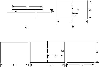
A coaxial-fed RMSA is shown in Figure 5.1. For L = 5 cm, W = 3 cm, and x = 0.9 cm, the BW for VSWR ≤ 2 is 129 MHz (4.8%) at the center frequency of 2.672 GHz.
A three gap-coupled RMSA configuration is shown in Figure 5.2, in which two rectangular parasitic patches are placed along the radiating edges of central coaxial-fed RMSA. For L = 5 cm, W = 3 cm, L 1 = 4 cm, s = 0.4 cm, and x = 2.4 cm, the BW is 463 MHz (15.4%) as described in Section 3.3.1.
To increase the BW further, two additional parasitic patches are placed along either side of the nonradiating edges of the centrally fed patch. A five gap-coupled RMSA configuration is shown in Figure 5.3(a). The parasitic
Figure 5.1 RMSA: (a) side and (b) top views.
Figure 5.2 Three gap-coupled RMSA with er = 1 and h = 0.5 cm.
|
|
|
|
|
|
|
Stacked Multiresonator MSAs |
173 |
||||||||||||||||||||||||
|
|
|
|
|
|
|
|
|
|
|
|
|
|
|
|
|
|
|
|
|
|
|
|
|
|
|
|
|
|
|
|
|
|
|
|
|
|
|
|
|
|
|
|
|
|
|
|
|
|
|
|
|
|
|
|
|
|
|
|
|
|
|
|
|
|
|
|
|
|
|
|
|
|
|
|
|
|
|
|
|
|
|
|
|
|
|
|
|
|
|
|
|
|
|
|
|
|
|
|
|
|
|
|
|
|
|
|
|
|
|
|
|
|
|
|
|
|
|
|
|
|
|
|
|
|
|
|
|
|
|
|
|
|
|
|
|
|
|
|
|
|
|
|
|
|
|
|
|
|
|
|
|
|
|
|
|
|
|
|
|
|
|
|
|
|
|
|
|
|
|
|
|
|
|
|
|
|
|
|
|
|
|
|
|
|
|
|
|
|
|
|
|
|
|
|
|
|
|
|
|
|
|
|
|
|
|
|
|
|
|
|
|
|
|
|
|
|
|
|
|
|
|
|
|
|
|
|
|
|
|
|
|
|
|
|
|
|
|
|
|
|
|
|
|
|
|
|
|
|
|
|
|
|
|
|
|
|
|
|
|
|
|
|
|
|
|
|
|
|
|
|
|
|
|
|
|
|
|
|
|
|
|
|
|
|
|
|
|
|
|
|
|
|
|
|
|
|
|
|
|
|
|
|
|
|
|
|
|
|
|
|
|
|
|
|
|
|
|
|
|
|
|
|
|
|
|
|
|
|
|
|
|
|
|
|
|
|
|
|
|
|
|
|
|
|
|
|
|
|
|
|
|
|
|
|
|
|
|
|
|
|
|
|
|
|
|
|
|
|
|
|
|
|
|
|
|
|
|
|
|
|
|
|
|
|
|
|
|
|
|
|
|
|
|
|
|
|
|
|
|
|
|
|
|
|
|
|
|
|
|
|
|
|
|
|
|
|
|
|
|
|
|
|
|
|
|
|
|
|
|
|
|
|
|
|
|
|
|
|
|
|
|
|
|
|
|
|
|
|
|
|
|
|
|
|
|
|
|
|
|
|
|
|
|
|
|
|
|
|
|
|
|
|
|
|
|
|
|
|
|
|
|
|
|
|
|
|
|
|
|
|
|
|
|
|
|
|
|
|
|
|
|
|
|
|
|
|
|
|
|
|
|
|
|
|
|
|
|
|
|
|
|
|
|
|
|
|
|
|
|
|
|
|
|
|
|
|
|
|
|
|
|
|
|
|
|
|
|
|
|
|
|
|
|
|
|
|
|
|
|
|
|
|
|
|
|
|
|
|
|
|
|
|
|
|
|
|
|
|
|
|
|
|
|
|
|
|
|
|
|
|
|
|
|
|
|
|
|
|
|
|
|
|
|
|
|
|
|
|
|
|
|
|
|
|
|
|
|
|
|
|
|
|
|
|
|
|
|
|
|
|
|
|
|
|
|
|
|
|
|
|
|
|
|
|
|
|
|
|
|
|
|
|
|
|
|
|
|
|
|
|
|
|
|
|
|
|
|
|
|
|
|
|
|
|
|
|
|
|
|
|
|
|
|
|
|
|
|
|
|
|
|
|
|
|
|
|
|
|
|
|
|
|
|
|
|
|
|
|
|
|
|
|
|
|
|
|
|
|
|
|
|
|
|
|
|
|
|
|
|
|
|
|
|
|
|
|
|
|
|
|
|
|
|
|
|
|
|
|
|
|
|
|
|
|
|
|
|
|
|
|
|
|
|
|
|
|
|
|
|
|
|
|
|
|
|
|
|
|
|
|
|
|
|
|
|
|
|
|
|
|
|
|
|
|
|
|
|
|
|
|
|
|
|
|
|
|
|
|
|
|
|
|
|
|
|
|
|
|
|
|
|
|
|
|
|
|
|
|
|
|
|
|
|
|
|
|
|
|
|
|
|
|
|
|
|
|
|
|
|
|
|
|
|
|
|
|
|
|
|
|
|
|
|
|
|
|
|
|
|
|
|
|
|
|
|
|
|
|
|
|
|
|
|
|
|
|
|
|
|
|
|
|
|
|
|
|
|
|
|
|
|
|
|
|
|
|
|
|
|
|
|
|
|
|
|
|
|
|
|
|
|
|
|
|
|
|
|
|
|
|
|
|
|
|
|
|
|
|
|
|
|
|
|
|
|
|
|
|
|
|
|
|
|
|
|
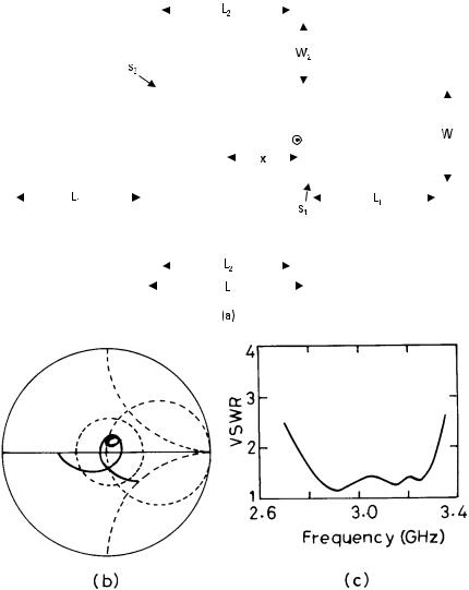
Figure 5.3 (a) Five gap-coupled RMSA and its (b) input impedance and (c) VSWR plots.
patches of length L 2 and width W2 along the nonradiating edges are chosen to be identical for symmetrical radiation pattern. The gap s2 between the fed and the parasitic patches along the nonradiating edges is taken smaller than s1, because the fields vary sinusoidally along the length of the patch. The width W2 of these parasitic patches is reduced to 2 cm, so that the orthogonal mode does not get excited. Because of the large BW of these

174 |
Broadband Microstrip Antennas |
configurations, the width of the patch along the nonradiating edges could become a resonant length at the higher frequency leading to the orthogonal polarization. This problem is not there for the patches placed along the radiating edges, because the central patch is fed along the middle of the width, ensuring that the fundamental mode corresponding to the width of the patch will not get excited.
For L 1 = 3.9 cm, L 2 = 4.2 cm, s1 = 0.4 cm, s2 = 0.05 cm, and x = 2.4 cm, the theoretical input impedance and VSWR plots, obtained using IE3D software [3], are shown in Figure 5.3(b, c). Two loops are formed in the impedance plot due to the parasitic elements along the radiating and the nonradiating edges. Both the loops are within the VSWR = 2 circle leading to the broad BW of 574 MHz (18.9%), which is more than the BW of the three gap-coupled RMSA. The radiation pattern of the antenna in the E- and H-planes at three frequencies (2.75, 3.05, and 3.32 GHz) is shown in Figure 5.4. In the H-plane, the pattern remains in the broadside direction at all the frequencies. In the E-plane, on the other hand, the
Figure 5.4 Radiation pattern of five gap-coupled RMSA on an air substrate at frequencies
(a) 2.75, (b) 3.05, and (c) 3.32 GHz: ( —— ) E-plane and ( - - - ) H-plane.
Stacked Multiresonator MSAs |
175 |
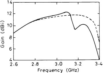
radiation pattern is in the broadside direction at the lower two frequencies, but three lobes are formed at the higher frequency. The two sidelobes are within 1 dB of the main lobe. This antenna can be used as a multiple-beam antenna at this frequency. These two sidelobes are due to the excitation of the parasitic patches along the radiating edges, which experience a large phase delay with respect to the fed patch at higher frequency. The variation of gain with frequency is shown in Figure 5.5. At the center frequency of 3.05 GHz, the gain is 12.1 dB. However, at the higher frequency, the gain decreases due to three lobes and has a dip at 3.15 GHz. A flatter gain is obtained when all the parasitic patches have equal length. For L 1 = L 2 = 3.9 cm, s1 = 0.4 cm, s2 = 0.1 cm and x = 2.4 cm, a single loop is observed in the input impedance plot instead of two loops when L 1 ≠ L 2. The BW reduces slightly to 548 MHz. The variation of gain with frequency is shown in Figure 5.5. The gain is more than 10 dB in the entire VSWR ≤ 2 BW.
Instead of using multiple resonators in the planar configuration, one patch is stacked on the other patch to increase the BW as described in Chapter 4. Only the bottom patch is fed and the top patch is electromagnetically coupled as shown in Figure 5.6(a). The patch on the bottom layer is shown in dotted lines and the patch on the top layer is shown in solid lines. For the parasitic patch length L 1 = 4.3 cm, air gap between the fed patch and the parasitic patch h1 = 0.4 cm, L = 5 cm, W = 3 cm, h = 0.5 cm, and x = 1.4 cm, the theoretical input impedance and VSWR plots are shown in
Figure 5.5 Gain variation with frequency of five gap-coupled RMSA: ( —— ) L 1 = 3.9 cm, L 2 = 4.2 cm and ( - - - ) L 1 = L 2 = 3.9 cm.