

glossary-legends(Джепессен иструкция )
.pdf2 MAR 12 |
INTRODUCTION |
ENROUTE-3 |
1 — Chart name.
2 — Chart number.
CHANGES
3 — Change note providing main changes made since previous revision.
AIRSPACE LIMITS AND CLASSIFICATION
1 — FIR/UIR, Country or Controlled airspace name. 3 — Airspace vertical limits. 2 — Airspace classification.
TABULATED DATA
1 — Airport Location name. IFR = Upper case. VFR = Upper/Lower case. 2 — Airport name.
3 — Charted location is shown by Area chart and/or panel number-letter combination. 4 — Communication information (includes call name, App, Arr, Dep, Twr, Gnd).
BOLD NAME – Voice Call T – Transmit only.
G – Guard only.
* – Part time operation. X – On request.
(R) – Radar capability.
Airport Broadcast Service frequencies (ATIS, ASOS, AWOS, etc.) are positioned over the airport label on face of chart.
Common EMERGENCY 121.5 – not listed
Refer to Glossary and Abbreviations in Introduction pages for further explanations. 5 — Bullet indicates multiple airports under same Location name.
© JEPPESEN, 2012. ALL RIGHTS RESERVED.
ENROUTE-4 |
INTRODUCTION |
2 MAR 12 |
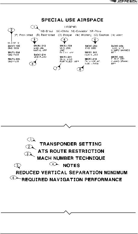
SPECIAL USE AIRSPACE
1 — Legend which includes: Affected Country ICAO ident Charted airspace types
2 — Tabulation change date.
3 — Country ICAO ident.
4 — Airspace type.
5 — Airspace ident.
6 — Airspace vertical limits.
7 — Airspace clearance approval agency.
8 — Times of Operation. H24 if not specified.
NOTE: Special use Airspace between GND/MSL and 2000’ is not depicted on Enroute and Area charts in several regions.
REFERENCE NOTES
1 — Settings and Procedures for Transponder Operations.
2 — Restrictions associated with ATS routes within a given FIR or UIR. 3 — Procedures for Mach Number reporting within a region or FIR/UIR. 4 — Notes which have operational significance to charted features.
5 — Procedures for RVSM Operations within a region or FIR/UIR.
6 — Procedures and RNP values listed for airways within a region or FIR/UIR.
© JEPPESEN, 2012. ALL RIGHTS RESERVED.
3 AUG 12 |
INTRODUCTION |
ENROUTE-5 |
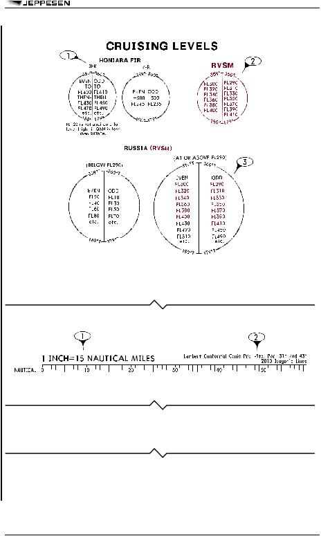
CRUISING LEVELS
1 — Country and/or ICAO specified cruising altitudes/levels.
2 — Standard RVSM Cruise Table associated with charted RVSM airspace. Non standard flight levels are depicted on the chart underneath the airway designator.
3 — Cruise Table which incorporates both Conventional and RVSM cruising altitudes/levels.
RANGE SCALE
1 — Chart scale in Nautical Miles.
2 — Chart Projection.
END PANEL
End Panels on Jeppesen Enroute Charts are primarily used for additional tabulated and reference information which can not all fit on the Cover Panel.
CHART GRAPHIC
The contents of an IFR Enroute chart include information provided by official government source, as well as, on rare occasion Jeppesen derived data. Charts are comprised of aeronautical data, cultural data, hydrography and on some charts terrain data.
© JEPPESEN, 2012. ALL RIGHTS RESERVED.
ENROUTE-6 |
INTRODUCTION |
3 AUG 12 |
© JEPPESEN, 2012. ALL RIGHTS RESERVED.

2 MAR 12 |
INTRODUCTION |
ENROUTE-7 |
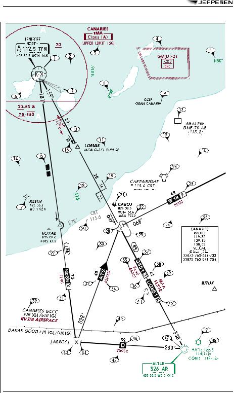
1 — VORDME. Low and High/Low charts include a Compass Rose with VHF Navaids. Shadow box indicates navaid is airway component, with frequency, identifier, Morse code and INS coordinates. Small "D" indicates DME/TACAN. Class indicated by: (T) Terminal, (L) Low, (H) High.
2 — Airports - Location name, Airport name (if different than Location name), ICAO identifier, airport elevation and longest runway length to nearest 100 feet with 70 feet as the dividing point (add 00). "s" indicates soft surface, otherwise hard surface. IFR Airport in blue - Published procedures filed under the location name. VFR airport in green.
3 — Controlled Airspace. Limits add 00. When sectorized vertically, lower limit indicated by under bar, upper limit indicated by over bar.
4 — Special use airspace.
5 — Grid Lat-Long values.
6 — CTR. Asterisks are used in association with Class C, D and E airspace in the US only to indicate part time operations, otherwise hours are H24.
7 — ILS available at airport.
8 — Magnetic Variation.
9 — Area chart coverage.
10 — Directional MEAs.
11 — Minimum Crossing Altitude (MCA).
12 — Change to adjoining Enroute chart.
13 — DME.
14 — Grid MORA. Values 10,000 feet and greater are maroon. Values less than 10,000 feet are green. Values are depicted in hundreds of feet.
15 — Gap in Nav Signal coverage.
16 — "D" indicates DME/TACAN fix. Segment mileage is DME/TACAN distance from navaid. Arrow without a "D" designates a reporting point from facility.
17 — Non Compulsory RNAV Waypoint.
18 — High Altitude Route included on some low charts for orientation only. 19 — Changeover Point between two navaids.
20 — Intersection or fix formation (Bearing, frequency and ident of remote VHF or LF navaid). 21 — Met report required.
22 — Minimum Reception Altitude (MRA).
23 — VORTAC - High Altitude and off-route Navaids do not include a Compass Rose. 24 — Uncontrolled airway or advisory route.
25 — Route Suffix. D or F indicates ATC Advisory services only. F or G indicates Flight Information services only.
26 — Enroute Communications.
27 — Total mileage between Navaids.
28 — Compulsory Reporting Point represented by screened fill. Non Compulsory Reporting point is open, no fill.
29 — Holding pattern.
30 — FIR/UIR Boundary name, identifier and Airspace Class.
31 — Route usability by non B-RNAV equipped aircraft (within Europe only). 32 — Unnamed, official published ATS route with direction indication.
33 — Uncontrolled Airspace (Class F or G).
34 — GPS MEA.
35 — Minimum Obstruction Clea rance Altitude (MOCA).
36 — Conditional Route Category (See Enroute Text pages Europe). 37 — Airway Designator.
38 — Segment mileage.
39 — Maximum Authorized Altitude (MAA).
40 — CNS/ATM Equipment Requirement Boundary.
41 — Non Standard Flight Levels (Even Flight Levels in direction indicated).
42 — RNAV ATS route when not identified by designator (used outside Europe).
© JEPPESEN, 2012. ALL RIGHTS RESERVED.
ENROUTE-8 |
INTRODUCTION |
2 MAR 12 |
43 — Named or unnamed airspace fix or mileage break. Database identifiers are enclosed in square brackets [ABROC]. They may be designated by the State (country) as Computer Navigation Fixes (CNFs) or derived by Jeppesen. These identifiers should not be used in filing flight plans nor should they be used when communicating with ATC; however they are also included in computer planning systems. They are shown only to enable the pilot to maintain orientation when using charts in concert with database navigation systems.
44 — Altitude Change.
45 — Route Minimum Off-Route Altitude (Route MORA).
46 — Direct Route (Requires ATC Approval, will not be accepted in Flight Plans). 47 — NDB.
48 — Communications related to Airport listed above Airport label. App/Arr, Dep, Twr and Gnd listed in Chart tabulations. Asterisk indicates part time operation.
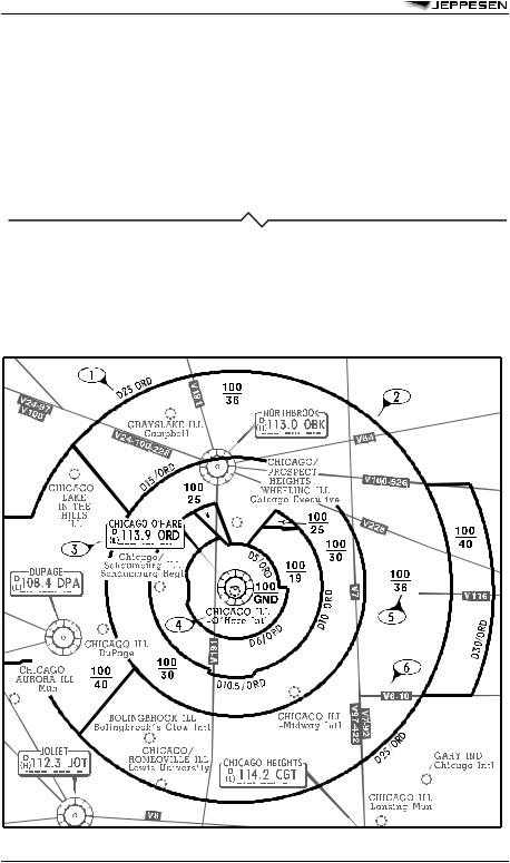
10–1B CHART LEGEND
10-1B charts depict the horizontal and vertical limits of Terminal airspace established by official source publications and provide orientation details for flights operating within the area. Associated airport communications are also included.
10-1B charts depicting US Class B airspace also includes general IFR and VFR Flight Procedures appropriate to that particular area.
SAMPLE 10–1B CONTENT
© JEPPESEN, 2012. ALL RIGHTS RESERVED.

2 MAR 12 |
INTRODUCTION |
ENROUTE-9 |
1 — DME arc distances used to define the Terminal airspace.
2 — Bold line represents the horizontal limits of the Terminal airspace and airspace sectors. 3 — Primary navaid used to further define the horizontal limits of the Terminal airspace.
4 — Primary airport is shown in bold print.
5 — Vertical limits of the Terminal airspace within charted sector in hundreds of feet.
6 — Screened information provided for orientation purposes. This includes airway information, airports and navaids.
END OF ENROUTE CHART LEGEND
© JEPPESEN, 2012. ALL RIGHTS RESERVED.
2 MAR 12 |
INTRODUCTION |
SID/STAR-1 |
SID/DP AND STAR CHART LEGEND
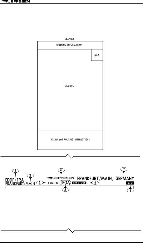
The SID & STAR section of the Jeppesen legend provides a general overview and depiction of Standard Instrument Departure (SID), Departure (DP), Standard Terminal Arrival Route/Standard Instrument Arrival (STAR), and Arrival charts. These charts are graphic illustrations of the procedures prescribed by the governing authority. A text description may be provided, in addition to the graphic, when it is supplied by the governing authority. All altitudes shown on SID/DP and STAR charts are MSL unless otherwise specified. All mileages are nautical, all radials and bearings are magnetic unless otherwise specified.
HEADING
1 — |
ICAO indicators and IATA identifiers. |
6 — |
Chart effective date. |
2 — |
Airport name. |
7 — Geographical location name. |
|
3 — |
Chart revision date. |
8 — |
Chart type identifier. |
4 — Jeppesen company logo. |
|
|
|
5 — |
Index number. |
|
|
|
Charts are sequenced alphabetical or by |
|
|
|
runway number within similar type arrivals or |
|
|
|
departures. |
|
|
© JEPPESEN, 2012. ALL RIGHTS RESERVED.
SID/STAR-2 |
INTRODUCTION |
2 MAR 12 |
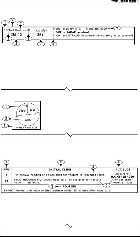
BRIEFING INFORMATION
1 — Indicates the service is part time.
2 — SID/DP Initial Departure Control Services or STAR Weather Services (e.g. ATlS) are depicted.
3 — Function of the service is shown when applicable.
4 — Service call sign is shown when transmit and receive, or transmit only ops are available. The call sign is omitted when the service is broadcast only or has a secondary function.
5 — All available primary frequencies are depicted.
6 — Indicates that radar services are available.
7 — Airport elevation is provided for Arrival/Departure airport.
8 — Procedure restrictions and instructions. Required equipment notes are prominently displayed.
9 — Transition Level and Altitude.
MINIMUM SAFE or SECTOR ALTITUDE (MSA)
1 — Sector defining Radial/Bearing, always depicted inbound for the Navaid, Fix or Airport Reference Point (ARP).
2 — Minimum safe/sector altitude.
3 — Navaid/Fix/ARP the MSA is predicated on.
NOTE: Normal coverage is a 25 NM radius from the forming facility/fix. If the protected coverage is other than 25 NM, that radius is depicted below the forming facility/fix. MSA is provided when specified by the governing authority for any procedure serving the airport.
CLIMB and ROUTING INSTRUCTIONS TABULATED TEXT BOX
Text description might be provided, in addition to the graphic, when it is supplied by the governing authority. Text should be used in conjunction with the graphic to fully understand the procedure to be flown. Neither the text nor the graphic is a stand alone representation of all instructions, speed, and altitude restrictions, but are a combined representation of the procedure.
Tabulated Text boxes, which include a wide variety of actions, instructions, or restrictions for the pilot, have certain common elements of design for SID, DP and STAR procedures.
1 — General identification applying to certain |
3 — Textual description, which compliments the |
sections of the procedure, such as Runway, |
graphic-based depictions or unique instructions, |
Arrival or SID identification. |
that cannot be graphically represented. |
2 — Segment of flight, such as Initial Climb, Routing, |
4 — General restriction that cannot be incorporated |
or Landing may be identified. |
in the graphic or that would enhance |
|
understanding of procedure. |
© JEPPESEN, 2012. ALL RIGHTS RESERVED.
2 MAR 12 |
INTRODUCTION |
SID/STAR-3 |
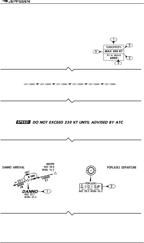
GRAPHIC — INFORMATION BOXES
Information boxes are generally tied to the track, fix, or navaid to which the information applies. The content is associated with the graphic depiction on SID, DP, and STAR charts. Information boxes include a wide variety of actions, instructions, or restrictions.
Though information boxes vary widely based on the complexity of procedures, they do have certain common elements of design.
1 — Heading, if included, represent the who, what, where, or why of the information box.
2 — Instruction lines are used to separate instructions and conditions for improved clarity.
3 — Instructions or conditional statements associated with track, fix, navaid, or procedure.
GRAPHIC — LOST COMMUNICATIONS PROCEDURE
Unique lost communication instructions, provided by the governing authority for a procedure, are placed within the graphic and are outlined by the lost communication boundary.
GRAPHIC — SPEED RESTRICTIONS
Speed restrictions that apply to the entire procedure are shown below the procedure title.
Speed restrictions vary widely within individual procedures. They can be in the tabulated text, boxed, and/or placed in information boxes at the associated track, fix or phase of flight.
GRAPHIC — STARTING POINT AND END POINT OF STAR, DP, AND SID PROCEDURES
Navaids, intersections, or waypoints identified in the procedure title are shown prominently for easy identification of the starting points on STARs, and the ending points on SID or DP procedures.
1 — Intersection or waypoint names are shown in larger text. 2 — Navaid boxes include a shadowed outline.
© JEPPESEN, 2012. ALL RIGHTS RESERVED.