

The motor step angle α , position θ , and speed ω are given by
α = |
2π |
[rad] |
θ = nα [rad] |
ω = |
α |
[rad/sec] |
|
spr |
δt |
||||||
|
|
|
|
|
where spr is the number of steps per round, n is the number of steps, and 1 rad/sec = 9,55 rpm
2.3 Linear speed ramp
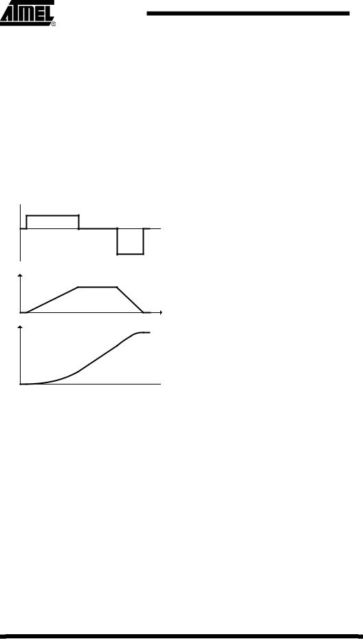
To start and stop the stepper motor in a smooth way, control of the acceleration and deceleration is needed. Figure 2-5 shows the relation between acceleration, speed and position. Using a constant acceleration/deceleration gives a linear speed profile.
Figure 2-5. Acceleration (ω& ), speed (ω ) and position (θ )
ω& 
 t
t
ω |
|
θ |
t |
|
 t
t
The time delay δt between the stepper motor pulses controls the speed. These time delays must be calculated in order to make the speed of the stepper motor follow the speed ramp as closely as possible.
Discrete steps control the stepper motor motion, and the resolution of the time delay between these steps is given by the frequency of the timer.
4 AVR446
8017A-AVR-06/06

AVR446
Figure 2-6. Speed profile vs. stepper motor pulses/speed
ω
|
|
|
|
|
|
|
|
|
|
|
pe |
|
|
|
|
|
|
|
|
|
|
o |
|
|
|
|
|
|
|
|
|
|
|
l |
|
|
|
|
|
|
|
|
|
s |
|
||
|
|
|
|
|
|
|
d |
|
|
||
|
|
|
|
|
|
e |
|
|
|
|
|
|
|
|
|
|
e |
|
|
|
|
|
|
|
|
|
|
|
sp |
|
|
|
|
|
|
|
|
|
|
d |
|
|
|
|
|
|
|
|
|
|
e |
|
|
|
|
|
|
|
|
|
|
r |
|
|
|
|
|
|
|
|
|
|
|
i |
|
|
|
|
|
|
|
|
|
|
s |
|
|
|
|
|
|
|
|
|
|
e |
|
|
|
|
|
|
|
|
|
|
|
d |
|
|
|
|
|
|
|
|
|
|
|
|
|
|
|
|
|
|
|
|
|
|
|
|
|
|
|
t |
t |
|
|
|
|
t |
|
1 |
|
t |
|
2c |
|
t |
|
|
|
|
0 |
δt = c t |
|
|
c t |
|
t |
|
3 |
|||||||
|
|
|
|
|
||||||||||||
|
|
|
|
|
|
|
|
|
|
|
||||||
|
|
|
0 |
t |
|
|
|
1 t |
|
|
2 |
t |
|
|
||
θ
 t
t
2.3.1 Exact calculations of the inter-step delay
The first counter delay c0 as well as succeeding counter delays cn, are given by (see appendix for details):
c0 |
= |
1 |
2α |
cn = c0 ( n + 1 − n ) |
tt |
& |
|||
|
|
ω |
|
The computational power of a microcontroller is limited, and calculating two square roots is time consuming. Therefore an approximation with less computational complexity is considered.
The counter value at the time n, using Taylor series approximation for the inter-step delay (see appendix for details) is given by:
2c
cn = cn−1 − 4n n−11
+
This calculation is much faster than the double square root, but introduces an error of 0.44 at n =1. A way to compensate for this error is by multiplying c0 with 0,676.
2.3.2 Change in acceleration
As shown in the appendix, the acceleration is given by c0 and n . If a change in acceleration (or deceleration) is done, a new n must be calculated.
The time tn and n as a function of the motor acceleration, speed and step angle are given by
5
8017A-AVR-06/06

ω n |
|
ωtn |
|
tn = |
|
n = |
& 2 |
& |
2α |
||
|
ω |
|
|
Merging these equation gives the relationship
nω& = ω 2
2α
This shows that the number of steps needed to reach a given speed is inversely
& |
& |
|
|
proportional to the acceleration: n1ω1 |
= n2 ω 2 |
|
|
|
& |
& |
n . |
This means that changing the acceleration from ω1 to |
ω 2 is done by changing |
||
This is shown in Figure 2-7 |
|
|
|
Figure 2-7. Up/down speed ramp
ω
ω&1 |
ω& 2 |
n1 |
t |
n2 |
Moving a given number of steps, deceleration must start at the right step to end at zero speed. The following equation is used to find n1 :
(n + n )ω&
n1 = (2 1 )2
ω&1 + ω& 2
6 AVR446
8017A-AVR-06/06