

330 / ОтКомпанииTI / doc7559Стеклопод
.pdfAVR480: Anti-Pinch System for Electrical Window
Automotive motorized window or door apparatus which closes automatically involve risks for trapping, squeezing or injury to people. They must reverse their movement in case the force applied by the motor gets higher than one normalized limit. The feature implies the constant monitoring of the speed, current, position of the glass. For cost and simplicity reasons, the system described in this application note uses universal brush motor equipped with hall effect sensors. The detection algorithm is based on speed and torque derivate and has been verified for robustness and fault tolerance. It is applicable to all ATMEL AVR® with A to D converter and Interrupt-on-Change I/O.
Microcontrollers
ApplicationNote
7559A–AVR–06/06
Powered
Equipments in
Modern Cars
The Standards
Today, electronic components and systems account for over 20% of the cost of a high end passenger car. The ability of dense electronics to better control sensors and actuators is utilized to enhance comfort and safety in cars and it is very predictable that most of the middle and upper class vehicles will be systematically equipped with motorized window or door systems.
The majority of these equipments come with full automation, means that they must be accompanied by safety systems to prevent people injury or mechanical degradations.
The legislation offers set of rules to which powered systems must comply. This is particularly true for window lifts or sliding doors. This application note describes how to implement an antipinch algorithm which was initially developed for a powered window but which can be easily adapted to any other moving part.
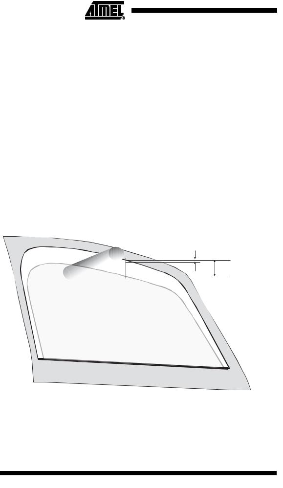
The automotive power-operated windows are governed by international standards, like MVSS118 in USA or 74/60/EEC in Europe. For those relatives to the elimination of danger to children, the requirements expressed in these documents can be summarized as follows (see Figure 1):
•Detection area: 4 mm to 200 mm,
•Maximum pinch force = 100N,
•Reverse direction on a pinch.
•Tests with determined deflection ratio objects: 5N/mm to 20N/mm
Figure 1. Anti-Pinch window lift rules as per MVSS118
4mm
200mm
2 AVR480
7559A–AVR–06/06

Hardware
Consideration
Anti-Pinch
Algorithm
Specification
Solution Using
Motor’s Physical
Parameters
Modeling,
Simulation
AVR480
Different detection strategies are possible to determine whether an obstacle is entering the critical pinching area:
•Without mechanical contact. It reacts before the pinch effort is exerted on the object. This is the optimal protection since no force is applied to the obstacle. It is also independent to vibration, aerodynamic variations, deformations. But, it requires integrated sensors (infrared, ultrasonic, ...) with their electronic modules and wires leading to additional costs.
•With mechanical contact. The pressure measurement will tell the system an object is being pinched. Also there, designers have two fundamental technologies available:
–Direct measurements: Force sensors or contactors are integrated on the door seal. These solutions are inherently high cost and reduce the styling for window/door designs
–Indirect measurements via physical monitoring. This is a globally cost optimized solution.
The pinch detection algorithm shall, at first, respect the standards (FMVSS118 & 74/60/EEC) requirements:
•Detection area from 4 to 200mm
•Maximum exerted force of 100N
•Reverse direction on Pinch detection
•Normalized tests for validation
It has to be adaptive since:
•The mechanical elements involved in the lift system will vary with time (ageing, local deformation, wear, ...)
•The electrical characteristics could evolve significantly
•The environment will affect the friction forces (temperature, moisture, freeze, etc.)
The system should not react to disturbances neither detect inopportune pinches. It must be
robust against air friction, road vibration, power-cuts, etc...
The force applied to the glass can be extrapolated from the current through the motor. The position of the moving elements permanently provides information on speed. Both parameters can then be used to determine whether an obstacle has been encountered and whether:
•It is in the detection area
•The force applied gets higher than the limit
This document describes one anti-pinch algorithm developed to work with motor current measurements and hall-effect speed indications. With very little changes, it can adapat to other systems like slidding doors or roof panels.
To better design the pinch-detection algorithm, the physical parameters involved in the lift system have been extracted. Starting from a generic description of an opening/closing aparatus, one more precise model has been developed for the powered window. It is broken down into several main components as illustrated in Figure 2.
3
7559A–AVR–06/06
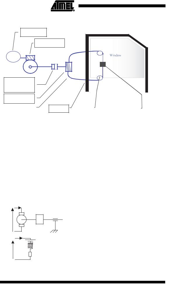
Figure 2. Powered Window Mechanical Components
Motor
Endless screw
M
« Flexible »
coupling
Non-linearity
Roller for cable
cable + sheath |
|
slides |
|
Pulley |
|
|
Cable window fixation |
|
|
|
|
|
|
|
|
|
|
Motor Model
The identification of the mechanical components leads to consider:
•Motor Effects
–Mechanical Parameters
–Electrical Parameters
•Window-Lift:
–Frictions (limited to slides)
–Machanical non-linearity (coupling mostly)
–Inertia (glass weight)
The DC universal motor used can be modeled using a very classical scheme as illustrated in Figure 3.
Figure 3. DC Motor Equivalent Model
|
|
|
U=Supply Voltage |
|
|
|
I(t)=Motor Current |
|
|
i(t) |
o=Rotation Speed |
|
|
Ω |
J= Inertia |
U |
|
J |
f= Frictions |
|
f |
(Inductor is not represented |
|
|
|
||
|
|
here: The DC motor has permanent |
|
|
|
|
|
|
|
E |
magnet) |
|
i(t) |
|
|
|
L |
E= Back (induced) Electromotive Force |
|
U |
|
||
|
|
L= Self-Inductance of the Armature |
|
|
|
|
R |
R= Equivalent Resistor of the Armature |
|
4 AVR480
7559A–AVR–06/06
 AVR480
Differential (t) and Laplace domain (p) equations are extracted for Electrical and Mechanical elements:
u(t) = E(t) +Ri(t) +L |
di |
|
U ( p) = E( p) +RI ( p) +LpI( p) |
|||
dt |
||||||
|
|
|
|
|||
E(t) = k Ω(t) |
E( p) = k Ω( p) |
|||||
M (t) = k i(t) , motor torque |
M ( p) = k I( p) |
|||||
J |
dΩ |
= M (t) − fΩ(t) |
|
|||
|
|
|||||
|
dt |
|
||||
JpΩ( p) = M ( p) + fΩ( p) |
|
|||||
The model chosen is a second order process. This allows the simulation of the motor, with its power supply (Voltage), including speed and current measurements. It also authorizes to inject disturbances or connect load (Co). It is detailed in Figure 4.
Figure 4. Second Order Motor Model
U |
|
|
|
1 |
|
|
I |
|
||
+ -- |
|
|
|
K |
||||||
|
|
|
|
R +Lp |
|
|
|
|
||
|
|
|
|
|
|
|
|
|
|
|
E
K
|
Cem |
M |
1 |
|
Ω |
||||||||
|
|
|
+ -- |
|
|||||||||
|
|
|
|
|
|
f + Jp |
|
|
|
|
|
||
|
|
|
|
|
|
|
|
|
|
|
|||
|
|
|
|
Co |
|
|
|
|
|
|
|
|
|
|
|
|
|
|
|
|
|
|
|
|
|
|
|
|
|
|
|
|
|
|
|
|
|
|
|
|
|
|
|
|
|
|
|
|
|
|
|
|
|||
|
|
|
|
|
|
|
|
|
|||||
|
|
|
Ω(p)= |
|
K*U(p) + Co(R+Lp) |
||||||||
|
|
|
|
|
|
||||||||
|
|
|
|
(f + Jp)(R + Lp) + K² |
|||||||||
Window-lift Model In addition to the DC motor model, the components from the window-lift system must be inserted. They are introduced to estimate the torque provided by the motor, and to access to position, speed and acceleration. The mechanical elements are described in Figure 5.
5
7559A–AVR–06/06
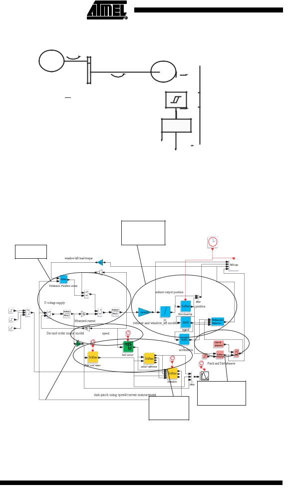
Figure 5. Window-lift Model
C1
M
C2
C1 ≈ nr (M&z&2 + Fv z&2 + Fs + Mg )
F
 Z
Z
 F1
F1
Z1
Z2
F2
Weight
Mg
This model is executed to obtain system behavior and to verify the pinch-detection algorithm. Described parameters and others (static and viscous frictions, weight,...) are tuned and introduced in the model to verify their influence.
Figure 6. Full Window-lift and Pinch-detection Algorithm Model
Mechanical components
motor
Pinch &
Disturbances
sensors |
Anti-pinch |
|
Algorithm |
||
|
6 AVR480
7559A–AVR–06/06

 AVR480
Pinch Detection
Algorithm
Pinching Condition
Usual pinch-detection algorithm operation is using indirect measurements out of the window-lift system:
•Current (torque)
•Position (speed)
The algorithm detailed in this document agregates two techniques based on
•Calibrated torque stored in non-volatile memory: Preliminary learning sequence is executed and torque values are stored in memory. This is quite memory consuming and requires regular calibration sequences
•Speed derivate calculation: Interesting method since it requires less memory but needs more computing power
and takes benefit from the two methodologies.
A pinch is detected by comparing the current measurement with a reference (see Figure 7).
M(t) ) kϕ x i(t) = K x i(t)
The threshold can be determined out of the Motor Torque constant (K) combined with the response time of the system (Motor and the load).
Figure 7. Condition for Pinch
i measured |
Pinch |
|
|
iref |
Threshold |
|
t |
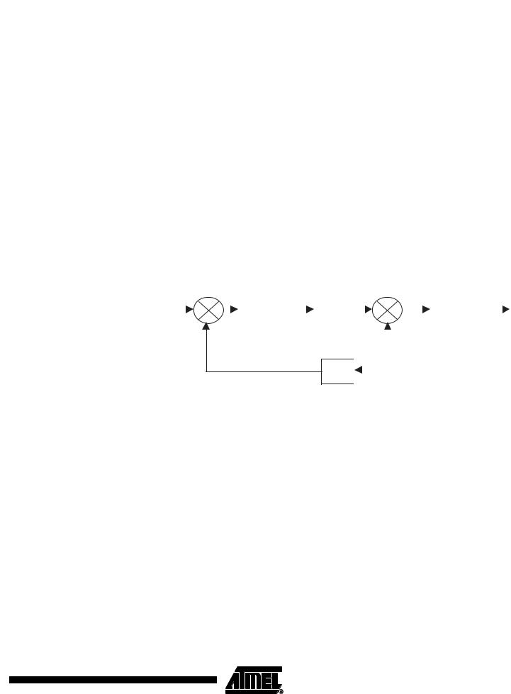
Current Reference One solution to elimnate need for calibration is to calculate expected current all along the mov- Synthesis ment. One pinch condition makes the speed decreasing and the current growing upassociated with increasing torque. Those two conditions are used to determinate the occurenco of a pinch.
In this document, speed derivate is preferred for its higher robustness to noise or fast disturbances.
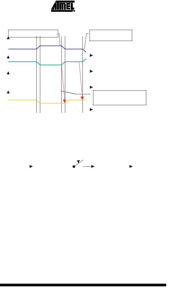
An example is given in Figure 8. The Current Reference (Iref) is permanently calculated until the speed increases or remains unchanged. As soon as the speed decreases rapidly (Derivate becomes negative), Iref is frozen. Current through the motor (Imot) continues to be measured and compared with Current Reference + Margin. In case Imot gets higher than the limit, then a Pinch is declared and several actions are taken by the application (First is to stop the motor and reverse its rotation to release the obstacle).
7
7559A–AVR–06/06
|
|
|
|
|
|
|
|
|
|
|
|
|
|
|
|
|
|
|
|
|
|
|
|
|
|
|
|
Figure 8. Example of a Pinch detection |
|
|
|
|
|||||||||
|
|
Example: blocking point |
|
|
|
Example: pinching |
|||||||
|
|
Rotation speed |
|
|
|
|
|||||||
|
|
|
|
|
|
||||||||
|
|
|
|
|
|
|
|
|
|
|
|
|
t |
|
|
Current Imot |
|
|
|
t |
|||||||
|
|
|
|
|
|
|
|
|
|
|
|
|
|
|
|
Derivate speed |
|
|
|
|
|
|
|
t |
|||
|
|
|
|
|
|
||||||||
|
|
|
|
|
|
|
|
|
|
|
|
|
|
|
|
|
|
|
|
|
|
|
|
|
|
|
When derivate is negative, |
|
|
|
|
|
|
|
|
|
|
|
|
|
|
|
|
Reference Iref |
|
|
|
reference is frozen |
|||||||
|
|
|
|
|
|
||||||||
|
|
|
|
|
|
|
|
|
|
|
|
|
t |
|
|
|
|
|
|
|
|
|
|
|
|
|
|
|
|
|
|
|
|
|
|
|
|
|
|
|
|
Algorithm Robustness The permanent calculation of the Iref allows for highly adaptative algorithm. To even increase the robustness of the alogrithm, the Current Reference is averaged over 8 consecutive measurements (see Figure 9).
Figure 9. Global Current Reference Synthesis Principle
|
|
|
|
|
|
Derivative speed |
|
|
|
Measured |
|
|
Imeas |
|
|
|
|
|
|
|
Average (8 |
|
Low pass (2 |
|
|
||||
|
|
|
|
|
|
|
|||
current Imot |
|
samples) |
Exploited current |
samples) |
Current |
||||
|
|
|
|
||||||
Reference Iref
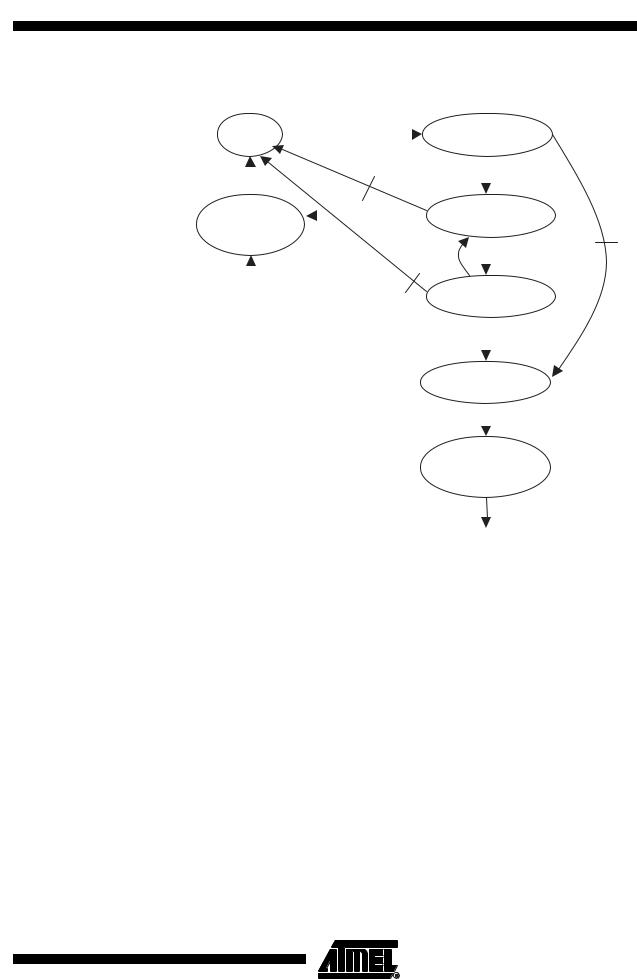
State Machine |
The main finite state machine (FSM) manages motor commands and pinch detection (Figure 10 |
|
presents states for upward movements. Downward operation is presented in Figure 11). |
8 AVR480
7559A–AVR–06/06
AVR480
Figure 10. Finite State Machine for Moving Upward Operation
Stop motor |
|
Upward Cmd |
|
|
|
|
|
Move up |
|||||||||
|
|
|
|
|
|
|
|
|
|
|
|||||||
Stop |
|
|
|
|
|
|
|
Start up |
|||||||||
|
|
|
High position |
||||||||||||||
Timeout |
|
|
|
|
|
|
|
|
|
|
|
|
backlash |
||||
|
|
|
|
|
|
|
|
|
|
|
|||||||
|
|
|
|
|
|
|
|
|
|||||||||
|
|
|
|
|
|
|
|||||||||||
stop motor |
|
|
|
|
|
|
Or Timeout |
|
|
|
|
|
|
||||
|
|
|
|
|
|
Go up |
|||||||||||
|
|
|
|
|
|
|
|
|
|
|
|||||||
Stopping |
|
|
|
|
|
|
|
|
|||||||||
|
|
|
|
|
|
|
|||||||||||
|
|
|
Cmd |
||||||||||||||
|
|
|
|
|
|
|
|
Timeout |
|||||||||
|
|
|
|
|
|
|
|
Out of area |
|
|
|
|
|
Pinch condition |
|||
|
|
|
|
|
|
High position |
|
|
|
|
|
|
|
||||
|
|
|
|
|
|
Obstruct |
|||||||||||
|
|
|
|
|
|
Ou Timeout |
|||||||||||
|
|
|
|
|
|
|
|
Stop motor |
|
|
|
|
|
Pinch area |
|||
|
|
|
|
|
|
|
|
|
|
|
|
|
|||||
|
|
|
|
|
|
|
|
|
|
|
|
|
|||||
|
|
|
|
|
|
|
|
|
|
|
|
|
|
||||
|
|
|
|
|
|
|
|
Pinch |
|||||||||
|
|
|
|
|
|
|
|
|
|
|
|
||||||
|
|
|
|
|
|
|
|
Move |
|
|
|
|
|
Delay (no current) |
|||
|
|
|
|
|
|
|
|
|
|
|
|
|
|||||
|
|
|
|
|
|
|
|
|
|
|
|
|
|||||
|
|
|
|
|
|
|
|
|
|
|
|
|
|
||||
|
|
|
|
|
|
|
|
downward |
Reverse |
||||||||
|
|
|
|
|
|
|
|
|
|
|
|
||||||
|
|
|
|
|
|
|
|
|
|
|
|
direction |
|||||
|
|
|
|
|
|
|
|
|
|
|
|
|
|
|
|
|
Out of pinch area |
|
|
|
|
|
|
|
|
|
|
|
|
|
|
|
|
|
|
|
|
|
|
|
|
|
|
|
|
|
|
|
|
|
|
|
|
9
7559A–AVR–06/06
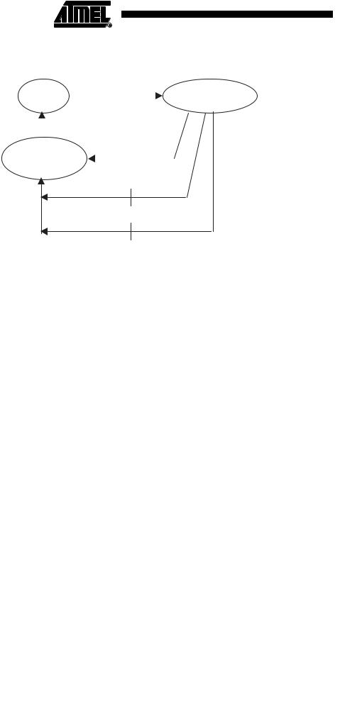
Other Interesting
Functions
Figure 11. Downwward Movement Finite State Machine
Stop motor |
Upward Cmd |
|
Move downward |
|||||||
|
|
|||||||||
Stop |
|
|
|
|
|
Move down |
||||
|
|
|
|
|||||||
|
|
|
|
|||||||
Timeout |
|
|
|
|
|
|
|
|
|
|
|
|
|
|
|
|
|
||||
Stop motor |
|
|
|
|
|
|
Cmd |
|
|
|
|
|
|
|
|
||||||
Stop |
|
|
|
|
||||||
|
|
|
|
|
|
|||||
request |
|
|
|
|
|
|
||||
Timeout
Bottom position Or Timeout
Calibrate / Init of the position
Not described here are secondary functions necessary for Window-lift operation:
•Measuring current, filtering
•Hall-Effect interrupt generation, counting, speed calculation, direction
•Push-button management
•Memorization of critical parameters (position, last operation direction, ...) in case of powerfail
Simulation Results Numerous simulations have be ran to assess and tune the different parameters for the detection threshold loop. Figure 12 visualizes how the speed and motor torque behave at the first and second ‘go-upward’ commands. Also, a pinch condition is injected at t=10s with a compression spring of 10N/mm.
Figure 13 shows the same curves but disturbances in motor torque are injected (frequency of 10Hz, 50N), after a second ‘go-upward’ command.
10 AVR480 
7559A–AVR–06/06