

Low Noise Micropower
2.5 V and 4.096 V
Precision Voltage References
ADR291/ADR292
FEATURES Supply Range
2.8 V to 15 V, ADR291
4.4 V to 15 V, ADR292 Supply Current 12 A Max
Low-Noise 8 V and 12 V p-p (0.1 Hz to 10 Hz)
High Output Current 5 mA Temperature Range 40 C to 125 C
Pin Compatible with REF02/REF19x
APPLICATIONS
Portable Instrumentation
Precision Reference for 3 V and 5 V Systems A/D and D/A Converter Reference Solar-Powered Applications Loop-Current-Powered Instruments
PIN CONFIGURATIONS
8-Lead SOIC (R-8)
NC |
|
|
|
|
|
1 |
|
8 |
NC |
||
VIN |
|
ADR29x |
|
NC |
|
2 |
7 |
||||
TOP VIEW |
|||||
|
|
|
|
||
NC |
3 |
(Not to Scale) |
6 |
V |
|
|
|
|
|
OUT |
|
|
|
|
|
NC |
|
GND |
4 |
|
5 |
||
|
|
|
|
|
NC = NO CONNECT
8-Lead TSSOP (RU-8)
NC |
|
|
|
|
|
1 |
|
8 |
NC |
||
VIN |
|
ADR29x |
|
NC |
|
2 |
7 |
||||
TOP VIEW |
|||||
|
|
|
|
||
NC |
3 |
(Not to Scale) |
6 |
V |
|
|
|
|
|
OUT |
|
|
|
|
|
NC |
|
GND |
4 |
|
5 |
||
|
|
|
|
|
NC = NO CONNECT
GENERAL DESCRIPTION
The ADR291 and ADR292 are low noise, micro-power precision voltage references that use an XFET® reference circuit. The new XFET architecture offers significant performance improvements over traditional band gap and buried Zener based references.
Improvements include one quarter the voltage noise output of band gap references operating at the same current, very low and ultralinear temperature drift, low thermal hysteresis, and excellent long-term stability.
The ADR29x family are series voltage references providing stable and accurate output voltages from supplies as low as 2.8 V for the ADR291. Output voltage options are 2.5 V and 4.096 V for the ADR291 and ADR292, respectively. Quiescent current is only
12 A, making these devices ideal for battery-powered instrumentation. Three electrical grades are available offering initial output accuracies of ± 2 mV, ± 3 mV, and ± 6 mV max for the ADR291, and ±3 mV, ±4 mV, and ±6 mV max for the ADR292. Temperature coefficients for the three grades are 8 ppm/°C, 15 ppm/°C, and 25 ppm/°C max, respectively. Line regulation and load regulation are typically 30 ppm/V and 30 ppm/mA, maintaining the reference’s overall high performance. For a device with 5.0 V output, refer to the ADR293 data sheet.
The ADR291 and ADR292 references are specified over the extended industrial temperature range of –40°C to +125°C. Devices are available in the 8-lead SOIC and 8-lead TSSOP packages.
ADR29x Product
Part Number |
Output Voltage (V) |
Initial Accuracy (%) |
Temperature Coefficient (ppm/ C) Max |
|
|
|
|
ADR291 |
2.500 |
0.08, 0.12, 0.24 |
8, 15, 25 |
ADR292 |
4.096 |
0.07, 0.10, 0.15 |
8, 15, 25 |
ADR293 |
5.000 |
(See ADR293 data sheet) |
|
|
|
|
|
REV. C
Information furnished by Analog Devices is believed to be accurate and reliable. However, no responsibility is assumed by Analog Devices for its use, nor for any infringements of patents or other rights of third parties that may result from its use. No license is granted by implication or otherwise under any patent or patent rights of Analog Devices. Trademarks and registered trademarks are the property of their respective owners.
One Technology Way, P.O. Box 9106, Norwood, MA 02062-9106, U.S.A. Tel: 781/329-4700 www.analog.com Fax: 781/326-8703 © 2003 Analog Devices, Inc. All rights reserved.
ADR291/ADR292
ADR291–SPECIFICATIONS
ELECTRICAL SPECIFICATIONS (VS = 3.0 V to 15 V, TA = 25 C, unless otherwise noted.)
Parameter |
Symbol |
Conditions |
Min |
Typ |
Max |
Unit |
|
|
|
|
|
|
|
E GRADE |
|
|
|
|
|
|
Output Voltage |
VO |
IOUT = 0 mA |
2.498 |
2.500 |
2.502 |
V |
Initial Accuracy |
VOERR |
|
–2 |
|
+2 |
mV |
|
|
|
–0.08 |
|
+0.08 |
% |
F GRADE |
|
IOUT = 0 mA |
2.497 |
2.500 |
2.503 |
V |
Output Voltage |
VO |
|||||
Initial Accuracy |
VOERR |
|
–3 |
|
+3 |
mV |
|
|
|
–0.12 |
|
+0.12 |
% |
G GRADE |
|
IOUT = 0 mA |
2.494 |
2.500 |
2.506 |
V |
Output Voltage |
VO |
|||||
Initial Accuracy |
VOERR |
|
–6 |
|
+6 |
mV |
|
|
|
–0.24 |
|
+0.24 |
% |
LINE REGULATION |
∆VO/∆VIN |
3.0 V to 15 V, IOUT = 0 mA |
|
30 |
100 |
ppm/V |
E/F Grades |
|
|||||
G Grade |
|
|
|
40 |
125 |
ppm/V |
|
|
|
|
|
|
|
LOAD REGULATION |
∆VO/∆ILOAD |
|
|
|
|
|
E/F Grades |
VS = 5.0 V, 0 mA to 5 mA |
|
30 |
100 |
ppm/mA |
|
G Grade |
|
|
|
40 |
125 |
ppm/mA |
|
|
|
|
|
|
|
LONG-TERM STABILITY |
∆VO |
After 1000 hrs of operation @ 125°C |
|
50 |
|
ppm |
NOISE VOLTAGE |
eN |
0.1 Hz to 10 Hz |
|
8 |
|
V p-p |
WIDEBAND NOISE DENSITY |
eN |
@ 1 kHz |
|
480 |
|
nV/√Hz |
ELECTRICAL SPECIFICATIONS (VS = 3.0 V to 15 V, TA = –25 C ≤ TA ≤ +85 C, unless otherwise noted.) |
|
|
||||
|
|
|
|
|
|
|
Parameter |
Symbol |
Conditions |
Min |
Typ |
Max |
Unit |
|
|
|
|
|
|
|
TEMPERATURE COEFFICIENT |
|
|
|
|
|
ppm/°C |
E Grade |
TCVO |
IOUT = 0 mA |
|
3 |
8 |
|
F Grade |
|
|
|
5 |
15 |
ppm/°C |
G Grade |
|
|
|
10 |
25 |
ppm/°C |
LINE REGULATION |
∆VO/∆VIN |
|
|
|
|
|
E/F Grades |
3.0 V to 15 V, IOUT = 0 mA |
|
35 |
125 |
ppm/V |
|
G Grade |
|
|
|
50 |
150 |
ppm/V |
LOAD REGULATION |
∆VO/∆ILOAD |
|
|
|
|
|
E/F Grades |
VS = 5.0 V, 0 mA to 5 mA |
|
20 |
125 |
ppm/mA |
|
G Grade |
|
|
|
30 |
150 |
ppm/mA |
ELECTRICAL SPECIFICATIONS (VS = 3.0 V to 15 V, TA = –40 C ≤ TA ≤ +125 C, unless otherwise noted.) |
|
|
||||
|
|
|
|
|
|
|
Parameter |
Symbol |
Conditions |
Min |
Typ |
Max |
Unit |
|
|
|
|
|
|
|
TEMPERATURE COEFFICIENT |
|
|
|
|
|
ppm/°C |
E Grade |
TCVO |
IOUT = 0 mA |
|
3 |
10 |
|
F Grade |
|
|
|
5 |
20 |
ppm/°C |
G Grade |
|
|
|
10 |
30 |
ppm/°C |
LINE REGULATION |
∆VO/∆VIN |
|
|
|
|
|
E/F Grades |
3.0 V to 15 V, IOUT = 0 mA |
|
40 |
200 |
ppm/V |
|
G Grade |
|
|
|
70 |
250 |
ppm/V |
LOAD REGULATION |
∆VO/∆ILOAD |
|
|
|
|
|
E/F Grades |
VS = 5.0 V, 0 mA to 5 mA |
|
20 |
200 |
ppm/mA |
|
G Grade |
|
|
|
30 |
300 |
ppm/mA |
|
|
|
|
|
|
|
SUPPLY CURRENT |
IS |
TA = 25°C |
|
9 |
12 |
A |
|
|
–40°C ≤ TA ≤ +125°C |
|
12 |
15 |
A |
THERMAL HYSTERESIS |
VO–HYS |
SOIC-8, TSSOP-8 |
|
50 |
|
ppm |
Specifications subject to change without notice.
–2– |
REV. C |
ADR291/ADR292
ADR292–SPECIFICATIONS
ELECTRICAL SPECIFICATIONS (VS = 5 V to 15 V, TA = 25 C, unless otherwise noted.)
Parameter |
Symbol |
Conditions |
Min |
Typ |
Max |
Unit |
|
|
|
|
|
|
|
E GRADE |
|
IOUT = 0 mA |
4.093 |
4.096 |
4.099 |
V |
Output Voltage |
VO |
|||||
Initial Accuracy |
VOERR |
|
–3 |
|
+3 |
mV |
|
|
|
–0.07 |
|
+0.07 |
% |
F GRADE |
|
|
|
|
|
|
Output Voltage |
VO |
IOUT = 0 mA |
4.092 |
4.096 |
4.1 |
V |
Initial Accuracy |
VOERR |
|
–4 |
|
+4 |
mV |
|
|
|
–0.10 |
|
+0.10 |
% |
G GRADE |
|
|
|
|
|
|
Output Voltage |
VO |
IOUT = 0 mA |
4.090 |
4.096 |
4.102 |
V |
Initial Accuracy |
VOERR |
|
–6 |
|
+6 |
mV |
|
|
|
–0.15 |
|
+0.15 |
% |
LINE REGULATION |
∆VO/∆VIN |
|
|
|
|
|
E/F Grades |
4.5 V to 15 V, IOUT = 0 mA |
|
30 |
100 |
ppm/V |
|
G Grade |
|
|
|
40 |
125 |
ppm/V |
LOAD REGULATION |
∆VO/∆ILOAD |
|
|
|
|
|
E/F Grades |
VS = 5.0 V, 0 mA to 5 mA |
|
30 |
100 |
ppm/mA |
|
G Grade |
|
|
|
40 |
125 |
ppm/mA |
LONG-TERM STABILITY |
∆VO |
After 1000 hrs of operation @ 125°C |
|
50 |
|
ppm |
NOISE VOLTAGE |
eN |
0.1 Hz to 10 Hz |
|
12 |
|
V p-p |
WIDEBAND NOISE DENSITY |
eN |
@ 1 kHz |
|
640 |
|
nV/√Hz |
ELECTRICAL SPECIFICATIONS (VS = 5 V to 15 V, TA = –25 C ≤ TA ≤ +85 C, unless otherwise noted.) |
|
|
||||
|
|
|
|
|
|
|
Parameter |
Symbol |
Conditions |
Min |
Typ |
Max |
Unit |
|
|
|
|
|
|
|
TEMPERATURE COEFFICIENT |
|
IOUT = 0 mA |
|
3 |
8 |
ppm/°C |
E Grade |
TCVO |
|
||||
F Grade |
|
|
|
5 |
15 |
ppm/°C |
G Grade |
|
|
|
10 |
25 |
ppm/°C |
LINE REGULATION |
∆VO/∆VIN |
|
|
|
|
|
E/F Grades |
4.5 V to 15 V, IOUT = 0 mA |
|
35 |
125 |
ppm/V |
|
G Grade |
|
|
|
50 |
150 |
ppm/V |
LOAD REGULATION |
∆VO/∆ILOAD |
VS = 5.0 V, 0 mA to 5 mA |
|
20 |
125 |
ppm/mA |
E/F Grades |
|
|||||
G Grade |
|
|
|
30 |
150 |
ppm/mA |
ELECTRICAL SPECIFICATIONS (VS = 5 V to 15 V, TA = –40 C ≤ TA ≤ +125 C, unless otherwise noted.) |
|
|
||||
|
|
|
|
|
|
|
Parameter |
Symbol |
Conditions |
Min |
Typ |
Max |
Unit |
|
|
|
|
|
|
|
TEMPERATURE COEFFICIENT |
|
IOUT = 0 mA |
|
3 |
10 |
ppm/°C |
E Grade |
TCVO |
|
||||
F Grade |
|
|
|
5 |
20 |
ppm/°C |
G Grade |
|
|
|
10 |
30 |
ppm/°C |
LINE REGULATION |
∆VO/∆VIN |
|
|
|
|
|
E/F Grades |
4.5 V to 15 V, IOUT = 0 mA |
|
40 |
200 |
ppm/V |
|
G Grade |
|
|
|
70 |
250 |
ppm/V |
LOAD REGULATION |
∆VO/∆ILOAD |
|
|
|
|
|
E/F Grades |
VS = 5.0 V, 0 mA to 5 mA |
|
20 |
200 |
ppm/mA |
|
G Grade |
|
|
|
30 |
300 |
ppm/mA |
SUPPLY CURRENT |
IS |
TA = 25°C |
|
10 |
15 |
A |
|
|
–40°C ≤ TA ≤ +125°C |
|
12 |
18 |
A |
THERMAL HYSTERESIS |
VO–HYS |
SOIC-8, TSSOP-8 |
|
50 |
|
ppm |
Specifications subject to change without notice.
REV. C |
–3– |

ADR291/ADR292
ABSOLUTE MAXIMUM RATINGS |
|
Supply Voltage .................................................................. |
18 V |
Output Short-Circuit Duration to GND .................... |
Indefinite |
Storage Temperature Range |
65°C to 150°C |
SO, RU Package ...................................... |
|
Operating Temperature Range |
40°C to 125°C |
ADR291/ADR292 ................................... |
|
Junction Temperature Range |
65°C to 125°C |
R, RU Package ........................................ |
|
Lead Temperature (Soldering, 60 sec) ............................ |
300°C |
NOTES
1.Stresses above those listed under Absolute Maximum Ratings may cause permanent damage to the device. This is a stress rating only; functional operation at or above this specification is not implied. Exposure to the above maximum rating conditions for extended periods may affect device reliability.
2.Remove power before inserting or removing units from their sockets.
Package Type |
JA* |
JC |
Unit |
8-Lead SOIC (R) |
158 |
43 |
°C/W |
8-Lead TSSOP (RU) |
240 |
43 |
°C/W |
*θJA is specified for worst-case conditions, i.e., θJA is specified for device in socket testing. In practice, θJA is specified for a device soldered in the circuit board.
ORDERING GUIDE
|
|
|
Temperature |
|
|
Number of |
|
Output |
Initial |
Coefficient |
Package |
Package |
Parts per |
Model |
Voltage |
Accuracy (%) |
Max (ppm/ C) |
Description |
Option |
Package |
|
|
|
|
|
|
|
ADR291ER |
2.50 |
0.08 |
8 |
SOIC |
R-8 |
98 |
ADR291ER-REEL7 |
2.50 |
0.08 |
8 |
SOIC |
R-8 |
1000 |
ADR291FR |
2.50 |
0.12 |
15 |
SOIC |
R-8 |
98 |
ADR291FR-REEL7 |
2.50 |
0.12 |
15 |
SOIC |
R-8 |
1000 |
ADR291FR-REEL |
2.50 |
0.12 |
15 |
SOIC |
R-8 |
2500 |
ADR291GR |
2.50 |
0.24 |
25 |
SOIC |
R-8 |
98 |
ADR291GR-REEL7 |
2.50 |
0.24 |
25 |
SOIC |
R-8 |
1000 |
ADR291GR-REEL |
2.50 |
0.24 |
25 |
SOIC |
R-8 |
2500 |
ADR291GRU-REEL7 |
2.50 |
0.24 |
25 |
TSSOP |
RU-8 |
1000 |
ADR291GT9 |
2.50 |
0.24 |
25 |
TO-92 |
T-9 |
98 |
ADR291GT9-REEL |
2.50 |
0.24 |
25 |
TO-92 |
T-9 |
2000 |
|
|
|
|
|
|
|
ADR292ER |
4.096 |
0.07 |
8 |
SOIC |
R-8 |
98 |
ADR292ER-REEL |
4.096 |
0.07 |
8 |
SOIC |
R-8 |
2500 |
ADR292FR |
4.096 |
0.10 |
15 |
SOIC |
R-8 |
98 |
ADR292FR-REEL7 |
4.096 |
0.10 |
15 |
SOIC |
R-8 |
1000 |
ADR292FR-REEL |
4.096 |
0.10 |
15 |
SOIC |
R-8 |
2500 |
ADR292GR |
4.096 |
0.15 |
25 |
SOIC |
R-8 |
98 |
ADR292GR-REEL7 |
4.096 |
0.15 |
25 |
SOIC |
R-8 |
1000 |
ADR292GRU |
4.096 |
0.24 |
25 |
TSSOP |
RU-8 |
98 |
ADR292GRU-REEL7 |
4.096 |
0.15 |
25 |
TSSOP |
RU-8 |
1000 |
|
|
|
|
|
|
|
See ADR293 data sheet for ordering guide.
OTHER XFET PRODUCTS
Part |
Nominal Output |
Package |
Number |
Voltage (V) |
Type |
|
|
|
ADR420 |
2.048 |
8-Lead MSOP/SOIC |
ADR421 |
2.50 |
8-Lead MSOP/SOIC |
ADR423 |
3.0 |
8-Lead MSOP/SOIC |
ADR425 |
5.0 |
8-Lead MSOP/SOIC |
|
|
|
CAUTION
ESD (electrostatic discharge) sensitive device. Electrostatic charges as high as 4000 V readily accumulate on the human body and test equipment and can discharge without detection. Although the ADR291/ADR292 features proprietary ESD protection circuitry, permanent damage may occur on devices subjected to high-energy electrostatic discharges. Therefore, proper ESD precautions are recommended to avoid performance degradation or loss of functionality.
–4– |
REV. C |

ADR291/ADR292
PARAMETER DEFINITIONS Line Regulation
The change in output voltage due to a specified change in input voltage. It includes the effects of self-heating. Line regulation is expressed in either percent-per-volt, parts-per-million-per-volt, or microvolts-per-volt change in input voltage.
Load Regulation
The change in output voltage is due to a specified change in load current. It includes the effects of self-heating. Load regulation is expressed in either microvolts-per-milliampere, parts-per-million-per-milliampere, or ohms of dc output resistance.
Long-Term Stability
Typical shift of output voltage at 25°C on a sample of parts subjected to a test of 1000 hours at 125°C.
∆VO = VO (t0 ) –VO(t1)
∆VO[ ppm]= VO (t0 ) –VO (t1) × 106
VO (t0 )
where:
VO (t0 ) = VO at 25°C at time 0
VO (t1 ) = VO at 25°C after 1000 hours operation at 125°C
Temperature Coefficient
The change of output voltage over the operating temperature change and normalized by the output voltage at 25°C, expressed in ppm/°C. The equation follows:
TCVO[ ppm /°C] = VO (T2 ) –VO (T1) × 106
VO (25°C) × (T2 – T1)
where:
VO (25°C) = VO at 25°C
VO(T1 ) = VO at Temperature 1
VO(T2 ) = VO at Temperature 2
NC = No Connect.
There are in fact internal connections at NC pins that are reserved for manufacturing purposes. Users should not connect anything at NC pins.
Thermal Hysteresis
Thermal hysteresis is defined as the change of output voltage after the device is cycled through temperature from +25°C to –40°C to +85°C and back to +25°C. This is a typical value from a sample of parts put through such a cycle.
VO – HYS = VO (25°C) –VO _ TC
= VO (25°C) –VO _ TC × 6
VO – HYS[ ppm] ° 10
VO (25 C)
where:
VO (25°C) = VO at 25°C
VO–TC = VO at 25°C after temperature cycle at +25°C to –40°C to +85°C and back to +25°C
REV. C |
–5– |
ADR291/ADR292–Typical Performance Characteristics
OUTPUT VOLTAGE – V
2.506 |
|
|
|
|
|
|
|
|
|
|
|
|
|
|
|
|
|
|
|
|
|
|
|
|
|
|
|
|
|
|
|
VS = 5V |
|
|
|
|
|
3 TYPICAL PARTS |
|
|
||||
2.504 |
|
|
|
|
|
|
|
|
|
|
|
|
|
|
|
|
|
|
|
|
|
|
|
|
|
|
|
|
|
2.502 |
|
|
|
|
|
|
|
|
|
|
|
|
|
|
|
|
|
|
|
|
|
|
|
|
|
|
|
|
|
2.500 |
|
|
|
|
|
|
|
|
|
|
|
|
|
|
|
|
|
|
|
|
|
|
|
|
|
|
|
|
|
2.498 |
|
|
|
|
|
|
|
|
|
|
|
|
|
|
|
|
|
|
|
|
|
|
|
|
|
|
|
|
|
2.496 |
|
|
|
|
|
|
|
|
|
|
|
|
|
|
|
|
|
|
|
|
|
|
|
|
|
|
|
|
|
2.494 |
|
|
|
|
|
|
|
|
|
|
|
|
|
|
–50 |
–25 |
0 |
25 |
50 |
75 |
100 |
125 |
|||||||
TEMPERATURE – C
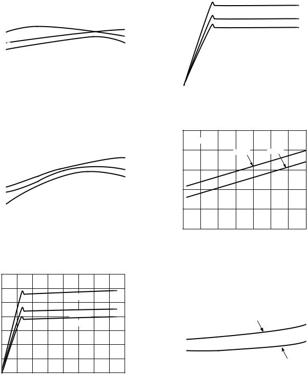
TPC 1. ADR291 VOUT vs. Temperature
|
16 |
|
|
|
|
|
|
|
|
|
|
|
|
|
|
|
|
|
|
|
|
|
|
|
|
|
|
|
|
|
|
|
|
|
|
|
|
|
14 |
|
|
|
|
|
|
|
|
|
|
|
|
|
|
|
|
|
|
|
|
|
|
|
|
|
|
|
|
|
|
|
|
|
|
|
|
|
|
|
|
|
|
|
|
|
|
|
|
|
|
|
|
|
|
|
A |
12 |
|
|
|
|
|
|
|
|
|
TA = +125 C |
|
|
|
|
|
||
|
|
|
|
|
|
|
|
|
|
|
|
|
||||||
– |
|
|
|
|
|
|
|
|
|
|
|
|
|
|
|
|
|
|
CURRENT |
10 |
|
|
|
|
|
|
|
|
|
TA = +25 C |
|
|
|
|
|
|
|
|
|
|
|
|
|
|
|
|
|
|
|
|
|
|
|
|||
|
|
|
|
|
|
|
|
|
|
|
|
|
|
|
|
|
|
|
|
|
|
|
|
|
|
|
|
|
|
|
|
|
|
|
|
|
|
|
8 |
|
|
|
|
|
|
|
|
|
TA = –40 C |
|
|
|
|
|
|
|
QUIESCENT |
6 |
|
|
|
|
|
|
|
|
|
|
|
|
|
|
|
|
|
|
|
|
|
|
|
|
|
|
|
|
|
|
|
|
|
|
|
|
|
4 |
|
|
|
|
|
|
|
|
|
|
|
|
|
|
|
|
|
|
|
|
|
|
|
|
|
|
|
|
|
|
|
|
|
|
|
|
|
2 |
|
|
|
|
|
|
|
|
|
|
|
|
|
|
|
|
|
|
|
|
|
|
|
|
|
|
|
|
|
|
|
|
|
|
|
|
|
0 |
|
|
|
|
|
|
|
|
|
|
|
|
|
|
|
|
|
|
0 |
2 |
4 |
6 |
8 |
10 |
12 |
14 |
16 |
|||||||||
INPUT VOLTAGE – V
TPC 4. ADR292 Quiescent Current vs. Input Voltage
|
4.102 |
|
|
|
|
|
|
|
|
|
|
|
|
|
|
|
|
|
|
|
|
|
|
|
|
|
|
|
|
|
|
|
|
|
|
|
|
|
|
|
|
|
|
|
|
|
|
|
|
|
|
|
|
VS = 5V |
|
|
|
|
|
|
3 TYPICAL PARTS |
|
|
||||
– V |
4.100 |
|
|
|
|
|
|
|
|
|
|
|
|
|
|
|
|
|
|
|
|
|
|
|
|
|
|
|
|
|
|
||
4.098 |
|
|
|
|
|
|
|
|
|
|
|
|
|
|
|
|
|
|
|
|
|
|
|
|
|
|
|
|
|
|
|
||
VOLTAGE |
|
|
|
|
|
|
|
|
|
|
|
|
|
|
|
|
4.096 |
|
|
|
|
|
|
|
|
|
|
|
|
|
|
|
|
OUTPUT |
|
|
|
|
|
|
|
|
|
|
|
|
|
|
|
|
4.094 |
|
|
|
|
|
|
|
|
|
|
|
|
|
|
|
|
|
|
|
|
|
|
|
|
|
|
|
|
|
|
|
|
|
|
4.092 |
|
|
|
|
|
|
|
|
|
|
|
|
|
|
|
|
|
|
|
|
|
|
|
|
|
|
|
|
|
|
|
|
|
4.090 |
|
|
|
|
|
|
|
|
|
|
|
|
|
|
|
|
–50 |
–25 |
0 |
25 |
50 |
75 |
100 |
125 |
||||||||
TEMPERATURE – C
TPC 2. ADR292 VOUT vs. Temperature
|
14 |
|
|
|
|
|
|
|
|
|
12 |
|
|
|
|
|
|
|
|
A |
10 |
|
|
|
|
TA = +125 C |
|
|
|
|
|
|
|
|
|
|
|
||
– |
|
|
|
|
|
|
|
|
|
CURRENT |
8 |
|
|
|
|
TA = +25 C |
|
|
|
|
|
|
|
|
|
|
|
||
|
|
|
|
|
TA = –40 C |
|
|
|
|
6 |
|
|
|
|
|
|
|
|
|
QUIESCENT |
|
|
|
|
|
|
|
|
|
4 |
|
|
|
|
|
|
|
|
|
|
|
|
|
|
|
|
|
|
|
|
2 |
|
|
|
|
|
|
|
|
|
0 |
2 |
4 |
6 |
8 |
10 |
12 |
14 |
16 |
|
0 |
||||||||
|
|
|
|
INPUT VOLTAGE – V |
|
|
|
||
|
14 |
|
|
|
|
|
|
|
|
|
VS = 5V |
|
|
|
|
|
|
|
12 |
|
|
ADR292 |
|
ADR291 |
|
|
– A |
10 |
|
|
|
|
|
|
|
CURRENT |
|
|
|
|
|
|
|
|
8 |
|
|
|
|
|
|
|
|
SUPPLY |
|
|
|
|
|
|
|
|
6 |
|
|
|
|
|
|
|
|
|
|
|
|
|
|
|
|
|
|
4 |
–25 |
0 |
25 |
50 |
75 |
100 |
125 |
|
–50 |
|||||||
|
|
|
|
TEMPERATURE – C |
|
|
|
|
TPC 5. ADR291/ADR292 Supply Current vs. Temperature
|
100 |
|
|
|
|
|
|
|
|
|
|
|
|
|
|
|
|
|
|
|
|
|
|
|
|
|
|
|
|
|
|
|
|
|
|
|
|
|
|
|
|
|
ADR291: |
VS = 3.0V TO 15V |
|
|
|
|
|
|
|
|
|
|
|
||||
|
|
|
ADR292: V |
S |
= 4.5V TO 15V |
|
|
|
|
|
IOUT = 0mA |
|
|
||||||
– ppm/V |
80 |
|
|
|
|
|
|
|
|
|
|
|
|
|
|
|
|
|
|
|
|
|
|
|
|
|
|
|
|
|
|
|
|
|
|
|
|
||
60 |
|
|
|
|
|
|
|
|
|
|
|
|
|
|
|
|
|
|
|
REGULATIONLINE |
|
|
|
|
|
|
|
|
|
|
|
|
|
|
|
|
|
|
|
|
|
|
|
|
|
|
|
|
|
|
|
|
|
|
|
|
|
||
|
|
|
|
|
|
|
|
|
ADR292 |
|
|
|
|
|
|
|
|
||
|
|
|
|
|
|
|
|
|
|
|
|
|
|
|
|
|
|
||
|
40 |
|
|
|
|
|
|
|
|
|
|
|
|
|
|
|
|
|
|
|
|
|
|
|
|
|
|
|
|
|
|
|
|
|
|
|
|
|
|
|
20 |
|
|
|
|
|
|
|
|
|
|
|
|
|
|
|
|
|
|
|
|
|
|
|
|
|
|
|
|
|
|
|
|
|
|
|
|
|
|
|
|
|
|
|
|
|
|
|
|
|
|
|
|
|
|
|
|
|
|
|
|
|
|
|
|
|
|
|
|
|
|
|
|
|
ADR291 |
|
|
|
|
|
0 |
|
|
|
|
|
|
|
|
|
|
|
|
|
|
|
|
|
|
|
–50 |
–25 |
|
0 |
25 |
50 |
75 |
100 |
|
125 |
|||||||||
TEMPERATURE – C
TPC 3. ADR291 Quiescent Current vs. Input Voltage |
TPC 6. ADR291/ADR292 Line Regulation vs. Temperature |
–6– |
REV. C |
|
100 |
ADR291: VS = 3.0V TO 7.0V |
|
|
|
|
|||
|
|
|
|
IOUT = 0mA |
|
||||
|
|
ADR292: V |
S |
= 4.5V TO 9.0V |
|
|
|
||
|
|
|
|
|
|
|
|
|
|
– ppm/V |
80 |
|
|
|
|
|
|
|
|
60 |
|
|
|
|
|
|
|
|
|
LINE REGULATION |
|
|
|
|
|
|
|
|
|
|
ADR291 |
|
|
|
|
|
|
||
40 |
|
|
|
|
|
|
|
|
|
20 |
|
|
|
|
|
|
ADR292 |
|
|
|
|
|
|
|
|
|
|
||
|
|
|
|
|
|
|
|
|
|
|
0 |
–25 |
|
0 |
25 |
50 |
75 |
100 |
125 |
|
–50 |
|
|||||||
|
|
|
|
|
TEMPERATURE – C |
|
|
|
|
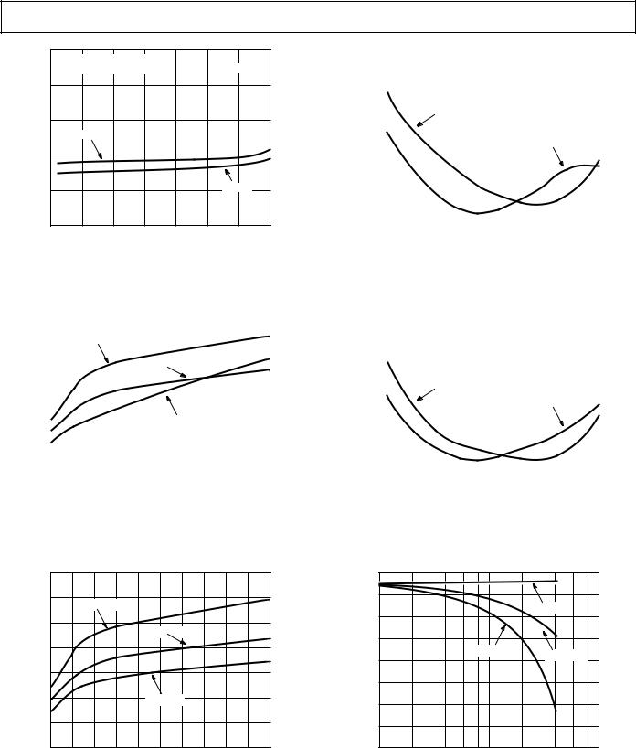
TPC 7. ADR291/ADR292 Line Regulation vs. Temperature
|
0.7 |
|
|
|
|
|
|
|
|
|
|
|
|
|
|
|
|
|
|
|
|
|
|
|
|
|
|
|
|
|
|
|
|
|
|
|
|
|
|
|
|
|
|
|
|
|
|
|
|
|
0.6 |
|
|
|
|
|
|
|
|
|
|
|
|
|
|
|
|
|
|
|
|
|
|
|
|
|
|
|
|
|
|
|
|
|
|
|
|
|
|
|
|
|
|
|
|
|
|
|
|
V |
|
|
|
|
TA = +125 C |
|
|
|
|
|
|
|
|
|
|
|
|
|
|
|
||||
– |
0.5 |
|
|
|
|
|
|
|
|
|
|
|
|
|
|
|
|
|
|
|
|
|
|
|
VOLTAGE |
|
|
|
|
|
|
|
|
|
|
|
|
|
|
|
|
|
|
|
|
|
|
|
|
|
|
|
|
|
|
|
|
|
|
|
|
|
|
|
|
|
|
|
|
|
|
|
||
|
|
|
|
|
|
|
|
|
|
|
TA = +25 C |
|
|
|
|
|
|
|
|
|
||||
|
|
|
|
|
|
|
|
|
|
|
|
|
|
|
|
|
|
|
|
|
||||
DIFFERENTIAL |
0.4 |
|
|
|
|
|
|
|
|
|
|
|
|
|
|
|
|
|
|
|
|
|
|
|
|
|
|
|
|
|
|
|
|
|
|
|
|
|
|
|
|
|
|
|
|
|
|
||
0.3 |
|
|
|
|
|
|
|
|
|
|
|
|
|
|
|
|
|
|
|
|
|
|
|
|
|
|
|
|
|
|
|
|
|
|
|
|
|
|
|
|
|
|
|
|
|
|
|
|
|
|
|
|
|
|
|
|
|
|
|
|
|
|
|
|
|
|
|
|
|
|
|
|
||
|
0.2 |
|
|
|
|
|
|
|
|
|
|
|
TA = –40 C |
|
|
|
|
|
|
|
|
|||
|
|
|
|
|
|
|
|
|
|
|
|
|
|
|
|
|
|
|
|
|
|
|
|
|
|
|
|
|
|
|
|
|
|
|
|
|
|
|
|
|
|
|
|
|
|
|
|
|
|
|
0.1 |
|
|
|
|
|
|
|
|
|
|
|
|
|
|
|
|
|
|
|
|
|
|
|
|
|
|
|
|
|
|
|
|
|
|
|
|
|
|
|
|
|
|
|
|
|
|
|
|
|
0 |
|
|
|
|
|
|
|
|
|
|
|
|
|
|
|
|
|
|
|
|
|
|
|
|
|
|
|
|
|
|
|
|
|
|
|
|
|
|
|
|
|
|
|
|
|
|
|
|
|
0 |
0.5 |
1.0 |
1.5 |
2.0 |
2.5 |
3.0 |
|
3.5 |
4.0 |
4.5 |
5.0 |
||||||||||||
|
|
|
|
|
|
|
|
|
LOAD CURRENT – mA |
|
|
|
|
|
|
|||||||||
TPC 8. ADR291 Minimum Input-Output Voltage Differential vs. Load Current
ADR291/ADR292
|
200 |
|
|
|
|
|
|
|
|
|
|
|
|
|
|
|
|
|
|
|
|
|
|
|
|
|
|
|
|
|
|
|
|
|
|
|
|
|
|
|
|
|
|
|
|
|
|
|
|
|
|
|
|
|
|
|
|
|
|
|
|
|
VS = 5V |
|
|
|
|
|
|
|
|
|
|
|
|
|
|||
ppm/mA |
160 |
|
|
|
|
|
|
|
|
|
|
|
|
|
|
|
|
|
|
|
|
|
|
|
|
|
|
|
|
|
|
|
|
|
|
|
|
||
|
|
|
|
|
|
|
|
|
|
|
|
|
|
|
|
|
|
||
|
|
|
|
|
IOUT = |
1mA |
|
|
|
|
|
|
|
|
|
|
|
||
– |
120 |
|
|
|
|
|
|
|
|
|
|
|
|
|
|
|
|
|
|
REGULATIONLOAD |
|
|
|
|
|
|
|
|
|
|
|
|
|
|
|
|
|
|
|
40 |
|
|
|
|
|
|
|
|
|
|
|
|
|
|
|
|
|
|
|
|
|
|
|
|
|
|
|
|
|
|
IOUT = 5mA |
|
|
|
|||||
|
|
|
|
|
|
|
|
|
|
|
|
|
|
|
|
||||
|
80 |
|
|
|
|
|
|
|
|
|
|
|
|
|
|
|
|
|
|
|
|
|
|
|
|
|
|
|
|
|
|
|
|
|
|
|
|
|
|
|
0 |
|
|
|
|
|
|
|
|
|
|
|
|
|
|
|
|
|
|
|
|
|
|
|
|
|
|
|
|
|
|
|
|
|
|
|
|
|
|
|
–50 |
–25 |
0 |
25 |
50 |
75 |
100 |
125 |
|||||||||||
TEMPERATURE – C
TPC 10. ADR291 Load Regulation vs. Temperature
|
200 |
|
|
|
|
|
|
|
|
|
|
|
|
|
|
|
|
|
|
|
|
|
|
|
|
|
|
|
|
|
|
|
|
|
|
|
|
|
|
|
|
|
|
|
|
|
|
|
|
|
|
|
|
|
|
|
|
|
|
VS = 5V |
|
|
|
|
|
|
|
|
|
|
|
|
|
||
– ppm/mA |
160 |
|
|
|
|
|
|
|
|
|
|
|
|
|
|
|
|
|
|
|
|
|
|
|
|
|
|
|
|
|
|
|
|
|
|
||
120 |
|
|
|
|
|
|
|
|
|
|
|
|
|
|
|
|
|
|
REGULATIONLOAD |
|
|
|
|
|
|
|
|
|
|
|
|
|
|
|
|
|
|
|
|
|
|
IOUT = 1mA |
|
|
|
|
|
|
|
|
|
|
|
|||
|
|
|
|
|
|
|
|
|
|
|
|
|
|
|
|
|||
|
|
|
|
|
|
|
|
|
|
|
|
|
|
|
|
|
|
|
|
80 |
|
|
|
|
|
|
|
|
|
|
I |
OUT = 5mA |
|
|
|
|
|
|
40 |
|
|
|
|
|
|
|
|
|
|
|
|
|
|
|
|
|
|
|
|
|
|
|
|
|
|
|
|
|
|
|
|
|
|
|
|
|
0 |
|
|
|
|
|
|
|
|
|
|
|
|
|
|
|
|
|
|
–50 |
–25 |
0 |
25 |
50 |
75 |
100 |
125 |
||||||||||
TEMPERATURE – C
TPC 11. ADR292 Load Regulation vs. Temperature
|
0.7 |
|
|
|
|
|
|
|
|
|
|
|
0.6 |
|
TA = +125 C |
|
|
|
|
|
|
||
– V |
|
|
|
|
|
|
|
|
|||
0.5 |
|
|
|
|
|
|
|
|
|
|
|
VOLTAGE |
|
|
|
|
|
|
|
|
|
|
|
|
|
|
|
|
TA = +25 C |
|
|
|
|
||
0.4 |
|
|
|
|
|
|
|
|
|
|
|
|
|
|
|
|
|
|
|
|
|
|
|
DIFFERENTIAL |
0.3 |
|
|
|
|
|
|
|
|
|
|
0.2 |
|
|
|
|
TA = –40 C |
|
|
|
|
||
|
|
|
|
|
|
|
|
|
|
|
|
|
0.1 |
|
|
|
|
|
|
|
|
|
|
|
0 |
|
1.0 |
1.5 |
2.0 |
2.5 |
3.0 |
3.5 |
4.0 |
4.5 |
|
|
0 |
0.5 |
5.0 |
||||||||
|
|
|
|
|
LOAD CURRENT – mA |
|
|
|
|||
TPC 9. ADR292 Minimum Input-Output Voltage Differential vs. Load Current
|
0 |
|
|
|
–250 |
|
|
V |
–500 |
|
TA = +25 C |
|
|
||
– |
|
|
|
|
|
|
|
NOMINAL |
–750 |
|
|
|
TA |
= –40 C |
|
–1000 |
|
TA = +125 C |
|
FROM |
–1250 |
|
|
|
|
|
|
OUT |
–1500 |
|
|
V |
|
|
|
|
|
|
|
|
–1750 |
|
|
|
–2000 |
1 |
10 |
|
0.1 |
||
|
|
SOURCING LOAD CURRENT – mA |
|
TPC 12. ADR291 ∆VOUT from Nominal vs. Load Current
REV. C |
–7– |

ADR291/ADR292
|
0 |
|
|
|
|
|
|
|
|
|
|
|
|
|
|
|
|
|
|
|
|
|
|
|
|
|
|
|
|
|
|
|
|
|
|
V |
–500 |
|
|
|
|
|
|
|
|
|
|
|
|
|
|
|
|
|
|
|
|
|
|
|
|
|
|
|
|
|
|
|
|
||
–1000 |
|
|
|
|
|
|
|
|
|
|
|
|
|
|
|
|
|
|
|
|
|
|
|
|
|
|
|
|
|
|
|
|
|
||
– |
|
|
|
|
|
|
|
|
|
|
|
TA = +25 C |
|
|
|||
NOMINAL |
–1500 |
|
|
|
|
TA = –40 C |
|
|
|
|
|
||||||
|
|
|
|
|
|
|
|
|
|
|
|
|
|
||||
|
|
|
|
|
|
|
|
|
|
|
|
|
|
|
|
|
|
|
–2000 |
|
|
|
|
|
|
|
|
|
TA = +125 C |
|
|
|
|
||
FROM |
–2500 |
|
|
|
|
|
|
|
|
|
|
|
|
|
|
|
|
|
|
|
|
|
|
|
|
|
|
|
|
|
|
|
|
||
OUT |
|
|
|
|
|
|
|
|
|
|
|
|
|
|
|
|
|
V |
–3000 |
|
|
|
|
|
|
|
|
|
|
|
|
|
|
|
|
|
|
|
|
|
|
|
|
|
|
|
|
|
|
|
|
|
|
|
|
|
|
|
|
|
|
|
|
|
|
|
|
|
|
|
|
|
–3500 |
|
|
|
|
|
|
|
|
|
|
|
|
|
|
|
|
|
|
|
|
|
|
|
|
|
|
|
|
|
|
|
|
|
|
|
–4000 |
|
|
|
|
|
|
|
|
|
|
|
|
|
|
|
|
|
|
1 |
|
10 |
|||||||||||||
|
0.1 |
|
|||||||||||||||
SOURCING LOAD CURRENT – mA
TPC 13. ADR292 ∆VOUT from Nominal vs. Load Current
|
|
1000 |
|
|
|
|
|
|
|
|
|
|
|
|
|
|
|
|
|
|
|
|
|
|
|
900 |
|
ADR292 |
|
|
VIN = |
15V |
|
||
|
Hz |
|
|
|
TA = 25 C |
|
|||||
|
|
|
|
|
|
|
|
||||
|
800 |
|
|
|
|
|
|
|
|||
|
|
|
|
|
|
|
|
|
|
||
|
|
|
|
|
|
|
|
|
|
||
|
–nV/ |
|
|
|
|
|
|
|
|
|
|
|
700 |
|
|
|
|
|
|
|
|
|
|
|
DENSITY |
|
|
|
|
|
|
|
|
|
|
|
600 |
|
|
ADR291 |
|
|
|
|
|||
|
|
|
|
|
|
|
|
||||
|
|
|
|
|
|
|
|
|
|
|
|
|
|
|
|
|
|
|
|
|
|
|
|
|
NOISE |
500 |
|
|
|
|
|
|
|
|
|
|
|
|
|
|
|
|
|
|
|
||
|
400 |
|
|
|
|
|
|
|
|
|
|
|
VOLTAGE |
|
|
|
|
|
|
|
|
|
|
|
300 |
|
|
|
|
|
|
|
|
|
|
|
|
|
|
|
|
|
|
|
|
|
|
|
|
200 |
|
|
|
|
|
|
|
|
|
|
|
|
|
|
|
|
|
|
|
|
|
|
|
100 |
|
|
|
|
|
|
|
|
|
|
|
|
|
|
|
|
|
|
|
|
|
0
10 100 1000 FREQUENCY – Hz
TPC 14. Voltage Noise Density vs. Frequency
|
120 |
|
|
|
|
|
|
|
|
|
|
|
|
|
|
|
|
|
|
|
|
|
|
|
|
|
|
|
|
|
|
|
|
|
|
|
|
|
|
|
|
|
|
|
– dB |
100 |
|
|
|
|
|
|
|
VS = 5V |
|
|
|
|
|
|
|
|
|
|
|
|
|
|
|
|
|
|||
|
|
|
|
|
|
|
|
|
|
|
|
|
||
|
|
|
|
|
|
|
|
|
|
|
|
|
||
80 |
|
|
|
|
|
|
|
|
|
|
|
|
|
|
|
|
|
|
|
|
|
|
|
|
|
|
|
||
|
|
|
|
|
|
|
|
|
|
|
|
|
||
REJECTION |
60 |
|
|
|
|
|
|
|
|
|
|
|
|
|
|
|
|
|
|
|
|
|
|
|
|
|
|
||
RIPPLE |
|
|
|
|
|
|
|
|
|
|
|
|
|
|
40 |
|
|
|
|
|
|
|
|
|
|
|
|
|
|
|
|
|
|
|
|
|
|
|
|
|
|
|
||
|
|
|
|
|
|
|
|
|
|
|
|
|
|
|
|
20 |
|
|
|
|
|
|
|
|
|
|
|
|
|
|
|
|
|
|
|
|
|
|
|
|
|
|
|
|
|
|
|
|
|
|
|
|
|
|
|
|
|
|
|
|
0 |
|
|
|
|
|
|
|
|
|
|
|
|
|
|
|
|
|
|
|
|
|
|
|
|
|
|
|
|
|
|
100 |
|
1000 |
||||||||||
|
10 |
|
||||||||||||
FREQUENCY – Hz
TPC 15. ADR291/ADR292 Ripple Rejection vs. Frequency
1s
100
90
2 V p-p
10
0%
TPC 16. ADR291 0.1 Hz to 10 Hz Noise
|
50 |
|
|
|
|
|
|
|
|
|
|
|
|
|
|
|
|
|
|
|
|
|
|
|
|
|
|
|
|
|
|
|
|
|
|
|
|
|
|
|
|
|
|
|
|
|
|
|
|
|
V |
S = 5V |
|
|
|
|
|
|
|
|
|
|
|
|
|
|
|
|
|
|
|
– |
40 |
|
IL = 0 mA |
|
|
|
|
|
|
|
|
|
|
|
|
|
|
|
|
|
|
||
|
|
|
|
|
|
|
|
|
|
|
|
|
|
|
|
|
|
|
|||||
|
|
|
|
|
|
|
|
|
|
|
|
|
|
|
|
|
|
|
|
|
|
||
|
|
|
|
|
|
|
|
|
|
|
|
|
|
|
|
|
|
|
|
|
|
||
|
|
|
|
|
|
|
|
|
|
|
|
|
|
|
|
|
|
|
|
|
|
|
|
|
|
|
|
|
|
|
|
|
|
|
|
|
|
|
|
|
|
|
|
|
|
|
|
IMPEDANCE |
30 |
|
|
|
|
|
|
|
|
|
|
|
|
|
|
|
|
|
|
|
|
|
|
|
|
|
|
|
|
|
|
|
|
|
|
|
|
|
|
|
|
|
|
|
|
|
|
OUTPUT |
20 |
|
|
|
|
|
|
|
|
|
|
|
|
|
|
|
|
|
|
|
|
|
|
|
|
|
|
|
|
|
|
|
|
|
|
|
|
|
|
|
|
|
|
|
|
||
|
|
|
|
|
|
|
|
|
|
|
|
|
|
|
|
|
|
|
|
|
|
||
10 |
|
|
|
|
|
|
|
|
|
|
|
|
|
|
|
|
|
|
|
|
|
|
|
|
|
|
|
|
|
|
|
|
|
|
|
|
|
|
|
|
|
|
|
|
|
||
|
|
|
|
|
|
|
|
|
|
|
|
|
|
|
|
|
|
|
|
|
|
|
|
|
|
|
|
|
|
|
|
|
|
|
|
|
|
|
|
|
|
|
|
|
|
|
|
|
0 |
|
|
|
|
|
|
|
|
|
|
|
|
|
|
|
|
|
|
|
|
|
|
|
|
|
|
|
|
|
|
|
|
|
|
|
|
|
|
|
|
|
|
|
|
|
|
|
0 |
10 |
100 |
|
|
|
1k |
|
|
10k |
|||||||||||||
FREQUENCY – Hz
TPC 17. ADR291 Output Impedance vs. Frequency
|
50 |
|
|
|
|
|
|
|
|
|
|
|
|
|
|
|
|
|
|
|
|
|
|
|
|
|
|
|
|
|
|
|
|
|
|
|
|
|
|
|
|
|
|
|
|
|
|
|
|
|
V |
S = 5V |
|
|
|
|
|
|
|
|
|
|
|
|
|
|
|
|
|
|
|
– |
40 |
|
IL = 0 mA |
|
|
|
|
|
|
|
|
|
|
|
|
|
|
|
|
|
|
||
|
|
|
|
|
|
|
|
|
|
|
|
|
|
|
|
|
|
|
|||||
|
|
|
|
|
|
|
|
|
|
|
|
|
|
|
|
|
|
|
|
|
|
||
|
|
|
|
|
|
|
|
|
|
|
|
|
|
|
|
|
|
|
|
|
|
||
|
|
|
|
|
|
|
|
|
|
|
|
|
|
|
|
|
|
|
|
|
|
|
|
|
|
|
|
|
|
|
|
|
|
|
|
|
|
|
|
|
|
|
|
|
|
|
|
IMPEDANCE |
30 |
|
|
|
|
|
|
|
|
|
|
|
|
|
|
|
|
|
|
|
|
|
|
|
|
|
|
|
|
|
|
|
|
|
|
|
|
|
|
|
|
|
|
|
|
|
|
OUTPUT |
20 |
|
|
|
|
|
|
|
|
|
|
|
|
|
|
|
|
|
|
|
|
|
|
|
|
|
|
|
|
|
|
|
|
|
|
|
|
|
|
|
|
|
|
|
|
||
|
|
|
|
|
|
|
|
|
|
|
|
|
|
|
|
|
|
|
|
|
|
||
10 |
|
|
|
|
|
|
|
|
|
|
|
|
|
|
|
|
|
|
|
|
|
|
|
|
|
|
|
|
|
|
|
|
|
|
|
|
|
|
|
|
|
|
|
|
|
||
|
|
|
|
|
|
|
|
|
|
|
|
|
|
|
|
|
|
|
|
|
|
|
|
|
|
|
|
|
|
|
|
|
|
|
|
|
|
|
|
|
|
|
|
|
|
|
|
|
0 |
|
|
|
|
|
|
|
|
|
|
|
|
|
|
|
|
|
|
|
|
|
|
|
|
|
|
|
|
|
|
|
|
|
|
|
|
|
|
|
|
|
|
|
|
|
|
|
0 |
10 |
100 |
|
|
|
1k |
|
|
10k |
|||||||||||||
FREQUENCY – Hz
TPC 18. ADR292 Output Impedance vs. Frequency
–8– |
REV. C |

ADR291/ADR292
|
IL = 5mA |
1ms |
OFF |
|
|
|
100 |
|
ON |
90 |
|
|
10 |
|
|
0% |
|
|
|
1V |
TPC 19. ADR291 Load Transient
IL = 5mA |
1ms |
CL = 1nF
100
OFF 90
ON
10
0%
1V
TPC 20. ADR291 Load Transient
IL = 5mA |
500 s |
100 |
|
90 |
|
10 |
|
0% |
|
|
1V |
TPC 22. ADR291 Turn-On Time
IL = 0mA |
10ms |
100 |
|
90 |
|
10 |
|
0% |
|
|
1V |
TPC 23. ADR291 Turn-Off Time
|
|
|
|
18 |
|
|
|
|
|
|
|
|
|
|
|
|
|
|
|
|
|
16 |
|
|
|
|
|
|
|
|
|
TEMPERATURE |
|
|
|
|
IL = 5mA |
5ms |
|
|
|
|
|
|
|
|
|
|
+25 C –40 C |
|
|
||
|
|
|
|
|
|
|
|
|
|
|
|
85 C |
+25 C |
|
|
||
|
CL = 100nF |
|
|
14 |
|
|
|
|
|
|
|
|
|
|
|
|
|
|
100 |
|
|
12 |
|
|
|
|
|
|
|
|
|
|
|
|
|
OFF |
90 |
|
FREQUENCY |
|
|
|
|
|
|
|
|
|
|
|
|
|
|
ON |
|
|
10 |
|
|
|
|
|
|
|
|
|
|
|
|
|
|
|
|
|
|
|
|
|
|
|
|
|
|
|
|
|
|
||
|
|
|
|
8 |
|
|
|
|
|
|
|
|
|
|
|
|
|
|
|
|
|
6 |
|
|
|
|
|
|
|
|
|
|
|
|
|
|
10 |
|
|
4 |
|
|
|
|
|
|
|
|
|
|
|
|
|
|
0% |
|
|
2 |
|
|
|
|
|
|
|
|
|
|
|
|
|
|
|
|
|
|
|
|
|
|
|
|
|
|
|
|
|
|
|
|
|
1V |
|
0 |
|
|
|
|
|
|
|
|
|
|
|
|
|
|
|
|
|
–180 |
–160 |
–140 |
–120 |
–100 |
–80 |
V |
–40 |
DEVIATION–20 0 20 40 |
– ppm80 100 120 |
140 160 180 |
200 |
MORE |
|
|
|
|
|
–200 |
|||||||||||||
|
|
|
|
|
|
|
|
|
|
|
–60 |
|
|
60 |
|
|
|
|
|
|
|
|
|
|
|
|
|
|
OUT |
|
|
|
|
|
|
TPC 21. ADR291 Load Transient |
TPC 24. Typical Hysteresis for the ADR291 Product |
REV. C |
–9– |