

PHOTOELECTRIC AMPLIFIER BUS SERIES
This new generation of photoelectric amplifiers, pioneers master/slave multiplexing technology in an innovative and flexible modular design. It challenges all conventional thinking on how a photoelectric system should function – and with a versatile design and wide range of unique features it promises more flexibility then ever thought imaginable. Above all, it can proudly be labelled with the performance heritage that Telco has become renowned for over the past 25 years.


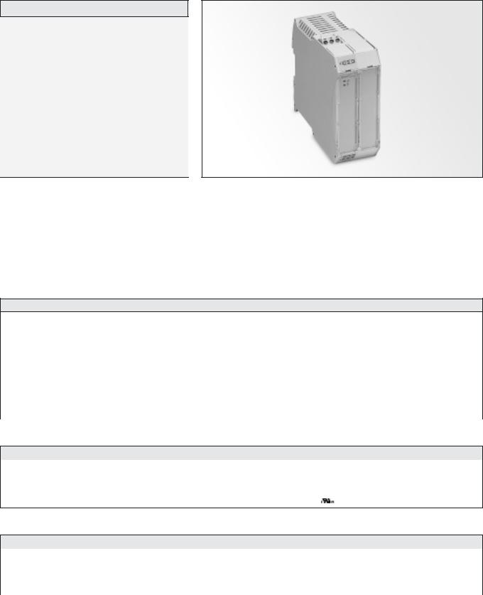
PHOTOELECTRIC AMPLIFIER BUS SERIES |
PAB 10 |
|
|
Description
Operation mode and max sensing range:
Thru beam: 0-70 m Diffuse proximity: 0-4 m
10 – 30 V dc and 24 V ac supply voltage
Manual sensitivity adjustment
Sensor LED-drive
Automatic sensor test
Adjustable on/off time delay
1 relay or 1 transistor output
Switch selectable light or dark function
Switch selectable long or short range
Test input
Power, output, alarm, signal level and master/slave address indicators
Alarm output
Removable connectors
DIN rail mounting
The PAB 10 is a 1-channel photoelectric amplifier, which is to be used in
conjunction with a set of remote transmitter LT and receiver LR from the
series 100, 110 and 120.
This amplifier series offers manual sensitivity adjustment via an integral
potentiometer located on the front panel of the amplifier. Output can
be selected from either a relay or transistor output, with an adjustable
0-10 sec on/off time delay. Light or dark function and long or short range
are switch selectable.
The amplifier can be connected together with up to 9 amplifiers, from the
PAB series, to form a modular master/slave system. The amplifiers are
connected via a rail bus connector positioned on the DIN rail. The bus
connection enables the channels of all the amplifiers to be multiplexed, which ensures that optical cross talk between channels is prevented. The bus connection enables communication between the amplifiers, which allows a common output from the amplifiers and a common power supply to the amplifiers in the bus connection.
The amplifier offers a test input, which is used for either disabling or enabling the transmitting power temporarily for test purposes. The amplifier includes an alarm output, which is used to indicate if the signal level is insufficient or if a sensor is faulty. The sensor LED drive powers the optional monitor LEDs available on the remote sensors – output (LT) and power (LR).
Technical Data
Supply voltage |
|
10 – 30 V dc or 24 V ac |
|
|
|
|
|
Voltage tolerance |
ac |
+/– 10 % |
|
|
|
|
|
Current consumption |
|
Max. 1,7 W |
|
|
|
|
|
Output |
Relay |
250 V ac / 3 A, 120 V ac / 5A |
|
|
|
||
Transistor |
30 V dc / 100 mA |
||
|
|||
|
|
|
|
Power on indicator |
|
Green LED |
|
|
|
|
|
Output indicator |
|
Yellow LED |
|
|
|
|
|
Signal level indicator |
|
Green LED |
|
|
|
|
|
Alarm indicator |
|
Red / yellow LED |
|
|
|
|
|
LR sensor failure indicator |
|
Yellow LED |
|
|
|
|
|
LT sensor failure indicator |
|
Red LED |
|
|
|
||
Master/slave address indicator |
Green / orange LED |
||
|
|
|
|
Sensor monitor LED drive |
|
Green monitor LED on receiver indicates ‘Power ON’ |
|
|
Yellow monitor LED on the transmitter indicates ‘PAB output activated’ |
||
|
|
||
|
|
|
|
Hysteresis |
|
Approx. 35 % |
|
|
|
|
|
|
Short range |
21 Hz |
|
|
Relay |
|
|
|
|
||
Operation frequency |
Long range |
12 Hz |
|
Short range |
|
||
42 Hz |
|||
|
|||
|
Transistor |
|
|
|
|
||
|
Long range |
17 Hz |
|
|
|
|
|
|
Short range |
27 ms / 20 ms |
|
|
Relay |
|
|
|
|
||
Response time tON / tOFF |
Long range |
45 ms / 38 ms |
|
Short range |
|
||
12 ms / 12 ms |
|||
|
|||
|
Transistor |
|
|
|
|
||
|
Long range |
30 ms / 30 ms |
|
|
|
|
|
Delay tON / tOFF |
|
0 – 10 sec, adjustable |
|
Housing material |
|
Polyamide |
|
|
|
|
|
REMOTE PHOTOELECTRIC SYSTEMS I 49
PAB 10 |
|
|
|
PHOTOELECTRIC AMPLIFIER BUS SERIES |
||
|
|
|
|
|
|
|
|
|
|
|
|
|
|
Environmental Data |
|
|
|
|
|
|
Temperature, operation |
|
|
|
|
– 10 to +50 ºC |
|
|
|
|
|
|
|
|
Temperature, storage |
|
|
|
|
– 40 to +80 ºC |
|
|
|
|
|
|
|
|
Sealing class |
|
|
|
|
IP 40 |
|
|
|
|
|
|
|
|
Approvals |
|
|
|
|
a |
|
|
|
|
|
|
|
|
|
|
|
|
|
|
|
Available Types |
|
|
|
|
|
|
Model |
|
Connection |
|
Supply Voltage |
|
10 – 30 V dc / 24 V ac |
|
|
|
|
|
||
|
Output |
|
Order Reference |
|||
|
|
|
|
|
||
|
|
|
|
|
|
|
PAB 10 |
|
|
|
1 individual relay |
|
PAB 10 A 009 |
|
|
|
|
|
|
|
Screw terminals |
|
1 individual NPN |
|
PAB 10 A 109 |
||
On/Off delay |
|
|
|
|||
|
|
|
|
|
|
|
|
|
|
|
1 individual PNP |
|
PAB 10 A 209 |
|
|
|
|
|
|
|
Note: Remote sensors and bus rail connector to be ordered separately.
Applicable Remote Sensors and Ranges
Series |
Mode |
|
Thru Beam |
|
Diffuse Proximity |
||
|
|
|
|
|
|
||
|
|
Short range |
|
Long range |
Short range |
|
Long range |
|
|
|
|
|
|
|
|
100 |
Single |
6 m |
|
18 m |
0,5 m |
|
1,1 m |
|
|
|
|
|
|
|
|
Bus Modular |
4 m |
|
12 m |
0,4 m |
|
0,8 m |
|
|
|
|
|||||
|
|
|
|
|
|
|
|
110 |
Single |
13 m |
|
40 m |
0,9 m |
|
2 m |
|
|
|
|
|
|
|
|
Bus Modular |
9 m |
|
27 m |
0,7 m |
|
1,7 m |
|
|
|
|
|||||
|
|
|
|
|
|
|
|
120 |
Single |
23 m |
|
70 m |
1,7 m |
|
4 m |
|
|
|
|
|
|
|
|
Bus Modular |
16 m |
|
47 m |
1,2 m |
|
2,6 m |
|
|
|
|
|||||
|
|
|
|
|
|
|
|
Response Times in Bus Connection
|
|
Relay |
|
|
Transistor |
||
|
|
|
|
|
|
|
|
|
Short range |
|
Long range |
Short range |
|
Long range |
|
|
|
|
|
|
|
|
|
tON |
6 ms x (N + 1) + 15 ms |
|
15 ms x (N + 1) + 15 ms |
6 ms x (N + 1) |
|
15 ms x (N + 1) |
|
Response time |
|
|
|
|
|
|
|
tOFF |
6 ms x (N + 1) + 8 ms |
|
15 ms x (N + 1) |
+ 8 ms |
6 ms x (N + 1) |
|
15 ms x (N + 1) |
Operation frequency |
83 Hz / (N + 2,9) |
|
33 Hz / (N + |
1,8) |
83 Hz / (N + 1) |
|
33 Hz / (N + 1) |
|
|
|
|
|
|
|
|
Note: “N” is equal to the total number of channels connected in the bus connection.
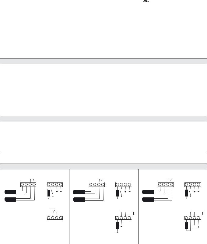
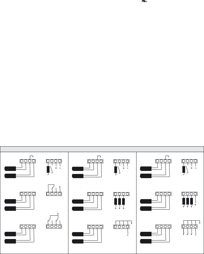
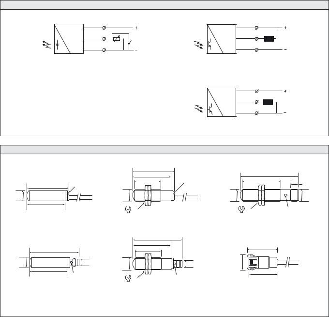
Wiring Diagrams
A 1 2 3 4 |
D 1 2 3 4 |
A 1 2 3 4 |
D 1 2 3 4 |
A 1 2 3 4 |
D 1 2 3 4 |
|||
Red |
|
|
Red |
|
|
Red |
|
|
LT |
Alarm |
Supply |
LT |
Alarm |
Supply |
LT |
Alarm |
Supply |
Black |
Black |
Black |
||||||
Shield |
load |
ac / dc |
Shield |
load |
ac / dc |
Shield |
load |
ac / dc |
|
Test |
|
Test |
|
Test |
|||
LR |
|
LR |
|
LR |
|
|||
Yellow |
|
|
Yellow |
|
|
Yellow |
|
|
|
|
|
|
|
Ch1 |
|
|
Ch1 |
|
E 1 2 3 4 |
|
E 1 2 3 4 |
|
E 1 2 3 4 |
|||
CNC NO Ch1
|
Load |
Load |
Relay output |
NPN output |
PNP output |
50 I REMOTE PHOTOELECTRIC SYSTEMS
PHOTOELECTRIC AMPLIFIER BUS SERIES |
|
PAB 10 |
|
|
|
|
|
|
|
|
|
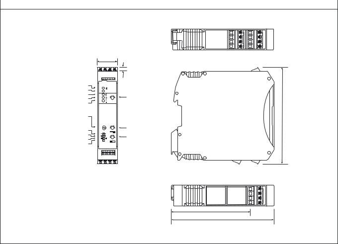
Dimensions and Descriptions |
|
|
|
|
|
|
|
|
|
|
|
|
4,3 |
|
Power on indicator |
|
|
Master/slave indicator |
|
|
Signal level indicator |
|
|
Output indicator |
10 |
|
Alarm indicator |
|
|
Master/slave selector |
108 |
|
Master – M |
|
|
Slave – 1-9 |
|
|
Long/short switch |
10 |
|
8 7 |
||
Light/dark switch |
Off delay adjustment |
|
Common/individual output switch |
||
10 |
||
|
||
Bus/single mode switch |
|
86
114
(Units in mm)
Telco reserves the right to change specifications without notice.
REMOTE PHOTOELECTRIC SYSTEMS I 51

PHOTOELECTRIC AMPLIFIER BUS SERIES |
PAB 20 |
|
|
Description
Operation mode and max sensing range:
Thru beam: 0-47 m Diffuse proximity: 0-2,6 m
10 – 30 V dc and 24 V ac supply voltage
Manual sensitivity adjustment
Sensor LED-drive
Automatic sensor test
Adjustable on/off time delay
2 relay or 2 transistor outputs
Switch selectable light or dark function
Switch selectable long or short range
Test input
Power, output, alarm, signal level and master/slave address indicators
Alarm output
Removable connectors
DIN rail mounting
The PAB 20 is a 2-channel, multiplexed, photoelectric amplifier, which is
to be used in conjunction with 2 sets of remote transmitters LT and
receivers LR from the series 100, 110 and 120. The 2 channels operate
independently of each other with their own set of remote transmitter and
receiver. The multiplexing function ensures that optical cross talk between
channels is prevented.
This amplifier series offers manual sensitivity adjustment, for each
individual channel, via an integral potentiometer located on the front panel
of the amplifier. The series offers a choice between 2 individual relay or 2
individual transistor outputs, with an adjustable 0-10 sec on/off time
delay. Light or dark function and long or short range are switch selectable.
The amplifier can be connected together with up to 9 amplifiers, from the
PAB series, to form a modular master/slave system. The amplifiers are connected via a rail bus connector positioned on the DIN rail. The bus connection enables the channels, of all the amplifiers, to be multiplexed. The bus connection enables communication between the amplifiers, which allows a common output from the amplifiers and a common power supply to the amplifiers in the bus connection.
The |
amplifier offers a test input, which is used |
for |
either |
disabling |
or |
enabling the transmitting power temporarily |
for |
test |
purposes. |
The amplifier includes an alarm output, which is used to indicate if the signal level is insufficient or if a sensor is faulty. The sensor LED drive powers the optional monitor LEDs available on the remote sensors – output (LT) and power (LR).
Technical Data
Supply voltage |
|
10 – 30 V dc or 24 V ac |
|
|
|
|
|
Voltage tolerance |
ac |
+/– 10 % |
|
|
|
|
|
Current consumption |
|
Max. 2,3 W |
|
|
|
|
|
Output |
Relay |
250 V ac / 3 A, 120 V ac / 5A |
|
|
|
||
Transistor |
30 V dc / 100 mA |
||
|
|||
|
|
|
|
Power on indicator |
|
Green LED |
|
|
|
|
|
Output indicator |
|
Yellow LED |
|
|
|
|
|
Signal level indicator |
|
Green LED |
|
|
|
|
|
Alarm indicator |
|
Red / yellow LED |
|
|
|
|
|
LR sensor failure indicator |
|
Yellow LED |
|
|
|
|
|
LT sensor failure indicator |
|
Red LED |
|
|
|
||
Master/slave address indicator |
Green / orange LED |
||
|
|
|
|
Sensor monitor LED drive |
|
Green monitor LED on receiver indicates ‘Power ON’ |
|
|
Yellow monitor LED on the transmitter indicates ‘PAB output activated’ |
||
|
|
||
|
|
|
|
Hysteresis |
|
Approx. 35 % |
|
|
|
|
|
|
Short range |
17 Hz |
|
|
Relay |
|
|
|
|
||
Operation frequency |
Long range |
9 Hz |
|
Short range |
|
||
28 Hz |
|||
|
|||
|
Transistor |
|
|
|
|
||
|
Long range |
11 Hz |
|
|
|
|
|
|
Short range |
33 ms / 26 ms |
|
|
Relay |
|
|
|
|
||
Response time tON / tOFF |
Long range |
60 ms / 53 ms |
|
Short range |
|
||
18 ms / 18 ms |
|||
|
|||
|
Transistor |
|
|
|
|
||
|
Long range |
45 ms / 45 ms |
|
|
|
|
|
Delay tON / tOFF |
|
0 – 10 sec, adjustable |
|
Housing material |
|
Polyamide |
|
|
|
|
|
REMOTE PHOTOELECTRIC SYSTEMS I 53
PAB 20 |
|
|
|
|
|
|
PHOTOELECTRIC AMPLIFIER BUS SERIES |
||||
|
|
|
|
|
|
|
|
|
|
|
|
|
|
|
|
|
|
|
|
|
|
|
|
Environmental Data |
|
|
|
|
|
|
|
|
|
|
|
Temperature, operation |
|
|
|
|
|
|
|
– 10 to +50 ºC |
|
|
|
|
|
|
|
|
|
|
|
|
|
|
|
Temperature, storage |
|
|
|
|
|
|
|
– 40 to +80 ºC |
|
|
|
|
|
|
|
|
|
|
|
|
|
|
|
Sealing class |
|
|
|
|
|
|
|
IP 40 |
|
|
|
|
|
|
|
|
|
|
|
|
|
|
|
Approvals |
|
|
|
|
|
|
|
a |
|
|
|
|
|
|
|
|
|
|
|
|
|
|
|
|
|
|
|
|
|
|
|
|
|
|
|
Available Types |
|
|
|
|
|
|
|
|
|
|
|
Model |
|
Connection |
|
|
|
Supply Voltage |
10 – 30 V dc / 24 V ac |
||||
|
|
|
|
|
|
|
|
|
|
||
|
|
|
Output |
|
Order Reference |
||||||
|
|
|
|
|
|
|
|
||||
|
|
|
|
|
|
|
|
|
|
|
|
PAB 20 |
|
|
|
|
|
2 individual relays |
|
PAB 20 A 009 |
|||
|
|
|
|
|
|
|
|
|
|
|
|
Screw terminals |
|
|
|
2 individual NPN |
|
PAB 20 A 109 |
|||||
On/Off delay |
|
|
|
|
|||||||
|
|
|
|
|
|
|
|
|
|
|
|
|
|
|
|
|
|
2 individual PNP |
|
PAB 20 A 209 |
|||
|
|
|
|
|
|
|
|
|
|||
Note: Remote sensors and bus rail connector to be ordered separately. |
|
|
|
|
|
||||||
|
|
|
|
|
|
|
|
|
|||
Applicable Remote Sensors and Ranges |
|
|
|
|
|
|
|
||||
Series |
|
|
|
|
Thru Beam |
Diffuse Proximity |
|||||
|
|
|
|
|
|
|
|
|
|
||
|
|
|
|
|
Short range |
|
Long range |
Short range |
|
Long range |
|
|
|
|
|
|
|
|
|
|
|
|
|
100 |
|
|
|
|
4 m |
|
12 m |
0,4 m |
|
0,8 m |
|
|
|
|
|
|
|
|
|
|
|
|
|
110 |
|
|
|
|
9 m |
|
27 m |
0,7 m |
|
1,7 m |
|
|
|
|
|
|
|
|
|
|
|
|
|
120 |
|
|
|
|
16 m |
|
47 m |
1,2 m |
|
2,6 m |
|
|
|
|
|
|
|
|
|
|
|||
Response Times in Bus Connection |
|
|
|
|
|
|
|
||||
|
|
|
|
|
|
|
Relay |
|
Transistor |
||
|
|
|
|
|
|
|
|
|
|
|
|
|
|
|
|
|
Short range |
|
Long range |
Short range |
|
Long range |
|
|
|
|
|
|
|
|
|
|
|
||
Response time |
tON |
|
6 ms x (N + 1) + 15 ms |
|
15 ms x (N + 1) + 15 ms |
6 ms x (N + 1) |
|
15 ms x (N + 1) |
|||
tOFF |
|
|
6 ms x (N + 1) + 8 ms |
|
15 ms x (N + 1) + 8 ms |
6 ms x (N + 1) |
|
15 ms x (N + 1) |
|||
|
|
|
|
|
|||||||
Operation frequency |
|
|
|
83 Hz / (N + 2,9) |
|
33 Hz / (N + 1,8) |
83 Hz / (N + 1) |
|
33 Hz / (N + 1) |
||
|
|
|
|
|
|
|
|
|
|
|
|
Note: “N” is equal to the total number of channels connected in the bus connection.
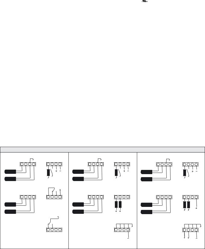
Wiring Diagrams
A 1 2 3 4 |
D 1 2 3 4 |
A 1 2 3 4 |
D 1 2 3 4 |
A 1 2 3 4 |
D 1 2 3 4 |
|||
Red |
|
|
Red |
|
|
Red |
|
|
LT1 |
Alarm |
Supply |
LT1 |
Alarm |
Supply |
LT1 |
Alarm |
Supply |
Black |
Black |
Black |
||||||
Shield |
load |
ac / dc |
Shield |
load |
ac / dc |
Shield |
load |
ac / dc |
LR1 |
Test |
|
LR1 |
|
Test |
LR1 |
|
Test |
|
|
|
|
|
|
|||
Yellow |
|
|
Yellow |
|
|
Yellow |
|
|
|
|
|
|
|
Ch1 Ch2 |
|
|
Ch1 Ch2 |
B 1 2 3 4 |
E 1 2 3 4 |
B 1 2 3 4 |
E 1 2 3 4 |
B 1 2 3 4 |
E 1 2 3 4 |
|||
Red |
C NC NO C |
Red |
|
|
Red |
|
|
|
Ch1 |
Ch2 |
|
|
|
|
|||
LT2 |
|
|
LT2 |
Load |
|
LT2 |
|
|
Black |
|
|
Black |
|
|
Black |
|
|
Shield |
|
|
Shield |
|
|
Shield |
|
|
LR2 |
|
|
LR2 |
|
|
LR2 |
|
|
Yellow |
|
|
Yellow |
|
|
Yellow |
|
|
|
F 1 2 3 4 |
|
F 1 2 3 4 |
|
F 1 2 3 4 |
|||
|
NC NO |
|
|
|
|
|
|
|
|
Ch2 |
|
|
|
|
|
|
|
Relay output |
|
NPN output |
|
PNP output |
|
|||
54 I REMOTE PHOTOELECTRIC SYSTEMS
PHOTOELECTRIC AMPLIFIER BUS SERIES |
PAB 20 |
|
|
|
|
|
|
|
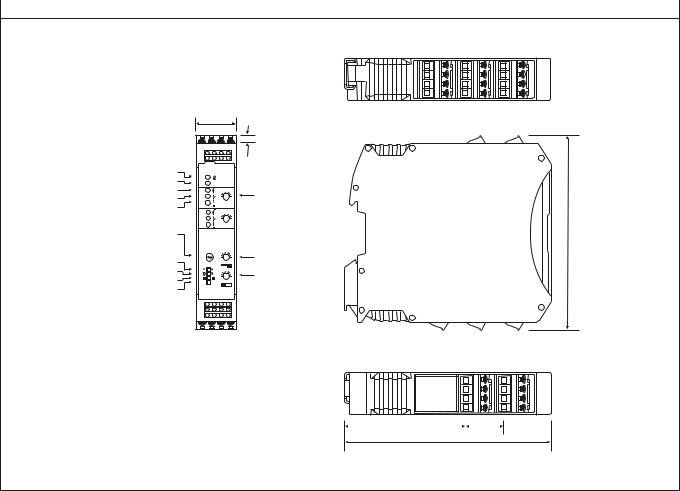
Dimensions and Descriptions |
|
|
|
|
|
|
4,3 |
|
Power on indicator |
|
|
Master/slave indicator |
|
|
Signal level indicator |
|
|
Output indicator |
10 |
|
Alarm indicator |
|
|
|
10 |
|
Master/slave selector |
108 |
|
Master – M |
|
|
Slave – 1-9 |
|
|
Long/short switch |
10 |
|
8 7 |
||
Light/dark switch |
Off delay adjustment |
|
Common/individual output switch |
||
10 |
||
|
||
Bus/single mode switch |
|
|
|
|
|
|
65 |
|
|
21 |
|
|
||||
114
(Units in mm)
Telco reserves the right to change specifications without notice.
REMOTE PHOTOELECTRIC SYSTEMS I 55

PHOTOELECTRIC AMPLIFIER BUS SERIES |
PAB 30 |
|
|
Description
Operation mode and max sensing range:
Thru beam: 0-47 m Diffuse proximity: 0-2,6 m
10 – 30 V dc and 24 V ac supply voltage
Manual sensitivity adjustment
Sensor LED-drive
Automatic sensor test
Adjustable on/off time delay
3 relay or 3 transistor outputs
Switch selectable light or dark function
Switch selectable long or short range
Test input
Power, output, alarm, signal level and master/slave address indicators
Alarm output
Removable connectors
DIN rail mounting
The PAB 30 is a 3-channel, multiplexed, photoelectric amplifier, which is
to be used in conjunction with 3 sets of remote transmitters LT and
receivers LR from the series 100, 110 and 120. The 3 channels operate
independently of each other with their own set of remote transmitter and
receiver. The multiplexing function ensures that optical cross talk between
channels is prevented.
This amplifier series offers manual sensitivity adjustment, for each
individual channel, via an integral potentiometer located on the front panel
of the amplifier. The series offers a choice between 3 individual relay or 3
individual transistor outputs, with an adjustable 0-10 sec on/off time
delay. Light or dark function and long or short range are switch selectable.
The amplifier can be connected together with up to 9 amplifiers, from the
PAB series, to form a modular master/slave system. The amplifiers are connected via a rail bus connector positioned on the DIN rail. The bus connection enables the channels of all the amplifiers to be multiplexed. The bus connection enables communication between the amplifiers, which allows a common output from the amplifiers and a common power supply to the amplifiers in the bus connection.
The amplifier offers a test input, which is used for either disabling or enabling the transmitting power temporarily for test purposes. The amplifier includes an alarm output, which is used to indicate if the signal level is insufficient or if a sensor is faulty. The sensor LED drive powers the optional monitor LEDs available on the remote sensors – output (LT) and power (LR).
Technical Data
Supply voltage |
|
10 – 30 V dc or 24 V ac |
|
|
|
|
|
Voltage tolerance |
ac |
+/– 10 % |
|
|
|
|
|
Current consumption |
|
Max. 2,6 W |
|
|
|
|
|
Output |
Relay |
250 V ac / 3 A, 120 V ac / 5A |
|
|
|
||
Transistor |
30 V dc / 100 mA |
||
|
|||
|
|
|
|
Power on indicator |
|
Green LED |
|
|
|
|
|
Output indicator |
|
Yellow LED |
|
|
|
|
|
Signal level indicator |
|
Green LED |
|
|
|
|
|
Alarm indicator |
|
Red / yellow LED |
|
|
|
|
|
LR sensor failure indicator |
|
Yellow LED |
|
|
|
|
|
LT sensor failure indicator |
|
Red LED |
|
|
|
||
Master/slave address indicator |
Green / orange LED |
||
|
|
|
|
Sensor monitor LED drive |
|
Green monitor LED on receiver indicates ‘Power ON’ |
|
|
Yellow monitor LED on the transmitter indicates ‘PAB output activated’ |
||
|
|
||
|
|
|
|
Hysteresis |
|
Approx. 35 % |
|
|
|
|
|
|
Short range |
14 Hz |
|
|
Relay |
|
|
|
|
||
Operation frequency |
Long range |
7 Hz |
|
Short range |
|
||
21 Hz |
|||
|
|||
|
Transistor |
|
|
|
|
||
|
Long range |
8 Hz |
|
|
|
|
|
|
Short range |
39 ms / 32 ms |
|
|
Relay |
|
|
|
|
||
Response time tON / tOFF |
Long range |
75 ms / 68 ms |
|
Short range |
|
||
24 ms / 24 ms |
|||
|
|||
|
Transistor |
|
|
|
|
||
|
Long range |
60 ms / 60 ms |
|
|
|
|
|
Delay tON / tOFF |
|
0 – 10 sec, adjustable |
|
Housing material |
|
Polyamide |
|
|
|
|
|
REMOTE PHOTOELECTRIC SYSTEMS I 57
PAB 30 |
|
|
|
|
|
|
PHOTOELECTRIC AMPLIFIER BUS SERIES |
||||
|
|
|
|
|
|
|
|
|
|
|
|
|
|
|
|
|
|
|
|
|
|
|
|
Environmental Data |
|
|
|
|
|
|
|
|
|
|
|
Temperature, operation |
|
|
|
|
|
|
|
– 10 to +50 ºC |
|
|
|
|
|
|
|
|
|
|
|
|
|
|
|
Temperature, storage |
|
|
|
|
|
|
|
– 40 to +80 ºC |
|
|
|
|
|
|
|
|
|
|
|
|
|
|
|
Sealing class |
|
|
|
|
|
|
|
IP 40 |
|
|
|
|
|
|
|
|
|
|
|
|
|
|
|
Approvals |
|
|
|
|
|
|
|
a |
|
|
|
|
|
|
|
|
|
|
|
|
|
|
|
|
|
|
|
|
|
|
|
|
|
|
|
Available Types |
|
|
|
|
|
|
|
|
|
|
|
Model |
|
Connection |
|
|
|
Supply Voltage |
10 – 30 V dc / 24 V ac |
||||
|
|
|
|
|
|
|
|
|
|
||
|
|
|
Output |
|
Order Reference |
||||||
|
|
|
|
|
|
|
|
||||
|
|
|
|
|
|
|
|
|
|
|
|
PAB 30 |
|
|
|
|
|
3 individual relays |
|
PAB 30 A 009 |
|||
|
|
|
|
|
|
|
|
|
|
|
|
Screw terminals |
|
|
|
3 individual NPN |
|
PAB 30 A 109 |
|||||
On/Off delay |
|
|
|
|
|||||||
|
|
|
|
|
|
|
|
|
|
|
|
|
|
|
|
|
|
3 individual PNP |
|
PAB 30 A 209 |
|||
|
|
|
|
|
|
|
|
|
|||
Note: Remote sensors and bus rail connector to be ordered separately. |
|
|
|
|
|
||||||
|
|
|
|
|
|
|
|
|
|||
Applicable Remote Sensors and Ranges |
|
|
|
|
|
|
|
||||
Series |
|
|
|
|
Thru Beam |
Diffuse Proximity |
|||||
|
|
|
|
|
|
|
|
|
|
||
|
|
|
|
|
Short range |
|
Long range |
Short range |
|
Long range |
|
|
|
|
|
|
|
|
|
|
|
|
|
100 |
|
|
|
|
4 m |
|
12 m |
0,4 m |
|
0,8 m |
|
|
|
|
|
|
|
|
|
|
|
|
|
110 |
|
|
|
|
9 m |
|
27 m |
0,7 m |
|
1,7 m |
|
|
|
|
|
|
|
|
|
|
|
|
|
120 |
|
|
|
|
16 m |
|
47 m |
1,2 m |
|
2,6 m |
|
|
|
|
|
|
|
|
|
|
|||
Response Times in Bus Connection |
|
|
|
|
|
|
|
||||
|
|
|
|
|
|
|
Relay |
|
Transistor |
||
|
|
|
|
|
|
|
|
|
|
|
|
|
|
|
|
|
Short range |
|
Long range |
Short range |
|
Long range |
|
|
|
|
|
|
|
|
|
|
|
||
Response time |
tON |
|
6 ms x (N + 1) + 15 ms |
|
15 ms x (N + 1) + 15 ms |
6 ms x (N + 1) |
|
15 ms x (N + 1) |
|||
tOFF |
|
|
6 ms x (N + 1) + 8 ms |
|
15 ms x (N + 1) + 8 ms |
6 ms x (N + 1) |
|
15 ms x (N + 1) |
|||
|
|
|
|
|
|||||||
Operation frequency |
|
|
|
83 Hz / (N + 2,9) |
|
33 Hz / (N + 1,8) |
83 Hz / (N + 1) |
|
33 Hz / (N + 1) |
||
|
|
|
|
|
|
|
|
|
|
|
|
Note: “N” is equal to the total number of channels connected in the bus connection.
Wiring Diagrams
A 1 2 3 4 |
D 1 2 3 4 |
A 1 2 3 4 |
D 1 2 3 4 |
A 1 2 3 4 |
D 1 2 3 4 |
|||
Red |
|
|
Red |
|
|
Red |
|
|
LT1 |
Alarm |
Supply |
LT1 |
Alarm |
Supply |
LT1 |
Alarm |
Supply |
Black |
Black |
Black |
||||||
Shield |
load |
ac / dc |
Shield |
load |
ac / dc |
Shield |
load |
ac / dc |
Test |
|
|
Test |
|
Test |
|||
LR1 |
|
LR1 |
|
LR1 |
|
|||
|
|
|
|
|
|
|||
Yellow |
|
|
Yellow |
|
|
Yellow |
|
|
|
|
|
|
|
Ch1 Ch2 Ch3 |
|
|
Ch1 Ch2 Ch3 |
B 1 2 3 4 |
E 1 2 3 4 |
B 1 2 3 4 |
E 1 2 3 4 |
B 1 2 3 4 |
E 1 2 3 4 |
|||
Red |
C NC NO C |
Red |
|
|
Red |
|
|
|
Ch1 |
Ch2/3 |
|
|
|
|
|||
LT2 |
|
|
LT2 |
Load |
|
LT2 |
Load |
|
Black |
|
|
Black |
|
|
Black |
|
|
Shield |
|
|
Shield |
|
|
Shield |
|
|
LR2 |
|
|
LR2 |
|
|
LR2 |
|
|
Yellow |
|
|
Yellow |
|
|
Yellow |
|
|
C 1 2 3 4 |
F 1 2 3 4 |
C 1 2 3 4 |
F 1 2 3 4 |
C 1 2 3 4 |
F 1 2 3 4 |
|||
Red |
NC NO NC NO |
Red |
|
|
Red |
|
|
|
Ch2 |
Ch3 |
|
|
|
|
|||
LT3 |
|
|
LT3 |
|
|
LT3 |
|
|
Black |
|
|
Black |
|
|
Black |
|
|
Shield |
|
|
Shield |
|
|
Shield |
|
|
LR3 |
|
|
LR3 |
|
|
LR3 |
|
|
Yellow |
|
|
Yellow |
|
|
Yellow |
|
|
Relay output |
|
NPN output |
|
PNP output |
|
|||
58 I REMOTE PHOTOELECTRIC SYSTEMS
PHOTOELECTRIC AMPLIFIER BUS SERIES |
PAB 30 |
|
|
|
|
|
|
|
Dimensions and Descriptions |
|
|
|
|
|
|
4,3 |
|
Power on indicator |
|
|
Master/slave indicator |
|
|
Signal level indicator |
|
|
Output indicator |
10 |
|
Alarm indicator |
|
|
|
10 |
|
Master/slave selector |
108 |
|
Master – M |
10 |
|
Slave – 1-9 |
|
|
Long/short switch |
10 |
|
8 7 |
||
Light/dark switch |
Off delay adjustment |
|
Common/individual output switch |
||
10 |
||
|
||
Bus/single mode switch |
|
|
|
|
|
|
|
|
|
|
|
|
|
44 |
|
|
21 |
|
|
21 |
|
|
|
||
|
|
|
|||||||||
|
|
|
|
|
|
|
|
|
|
|
|
|
|
114 |
|
|
|
|
|
|
|
||
(Units in mm)
Telco reserves the right to change specifications without notice.
REMOTE PHOTOELECTRIC SYSTEMS I 59
POWER PACK BUS SERIES |
PPB 00 |
|
|
Description
Switch mode power supply
110-240 V ac supply voltage
Power and overload indicators
DIN rail mounting
The PPB 00 is intended to be used in conjunction with the PAB series, where there is a need for AC supply voltage. This power pack supplies a 24 V dc supply to the photoelectric amplifier bus (PAB) modules connected together via a rail bus connector positioned on the DIN rail. The PPB 00 can power up to ten PAB modules connected via the bus connection.
The power pack offers a shut down feature for short circuit protection, which ensures that if an external voltage is connected to a PAB module, while connected to the power pack, then the PPB 00 will shut down. This prevents a short circuit between the power pack and the external power supply.
Technical Data
Supply voltage |
110-240 V ac |
|
|
Voltage tolerance |
–15 % / + 10 % |
|
|
Current consumption |
Max. 60 VA |
|
|
Supply output voltage |
24 V dc |
|
|
Output load |
1,2 A |
|
|
Output power |
29 W |
|
|
Power on indicator |
Green LED |
|
|
Overload indicator |
Red LED |
|
|
Housing material |
Polymide |
|
|
Environmental Data
Temperature, operation |
– |
20 to +55 ºC |
|
|
|
Temperature, storage |
– |
40 to +80 ºC |
|
|
|
Sealing class |
|
IP 40 |
|
|
|
Approvals |
|
a |
|
|
|
Available Types
Model |
Supply Voltage |
110 – 240 V ac |
|
|
|
||
Connection |
Order Reference |
||
|
|||
|
|
|
|
PPB 00 |
Screw terminals |
PPB 00 A 909 |
|
|
|
|
Note: Bus connector to be ordered separately.
REMOTE PHOTOELECTRIC SYSTEMS I 61
PPB 00 |
|
|
|
POWER PACK BUS SERIES |
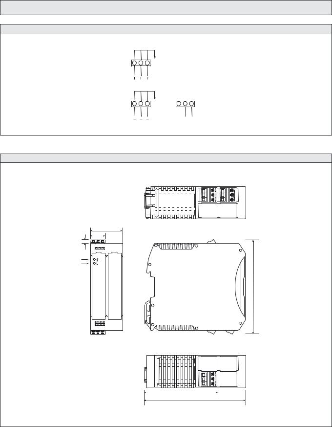
Wiring Diagrams |
|
|
|
|
|
|
24 V dc |
|
|
D |
1 |
2 |
3 |
|
|
|
0 V dc |
|
|
E |
1 |
2 |
3 |
B 1 2 3 |
|
|
|
|
~ |
|
|
|
|
ac supply |
Dimensions and Descriptions
36
Power on indicator
Overload indicator
108
82
114
(Units in mm)
Telco reserves the right to change specifications without notice.
62 I REMOTE PHOTOELECTRIC SYSTEMS

SPACEMASTER SERIES
True to its original concept, the SpaceMaster series is diverse in every sense of the word. There is a sensor suitable for every industry out there. And this can easily be justified by the thousands of sites where these infrared sensors operate relentlessly and problem-free day-after-day. That’s the only way it should be.

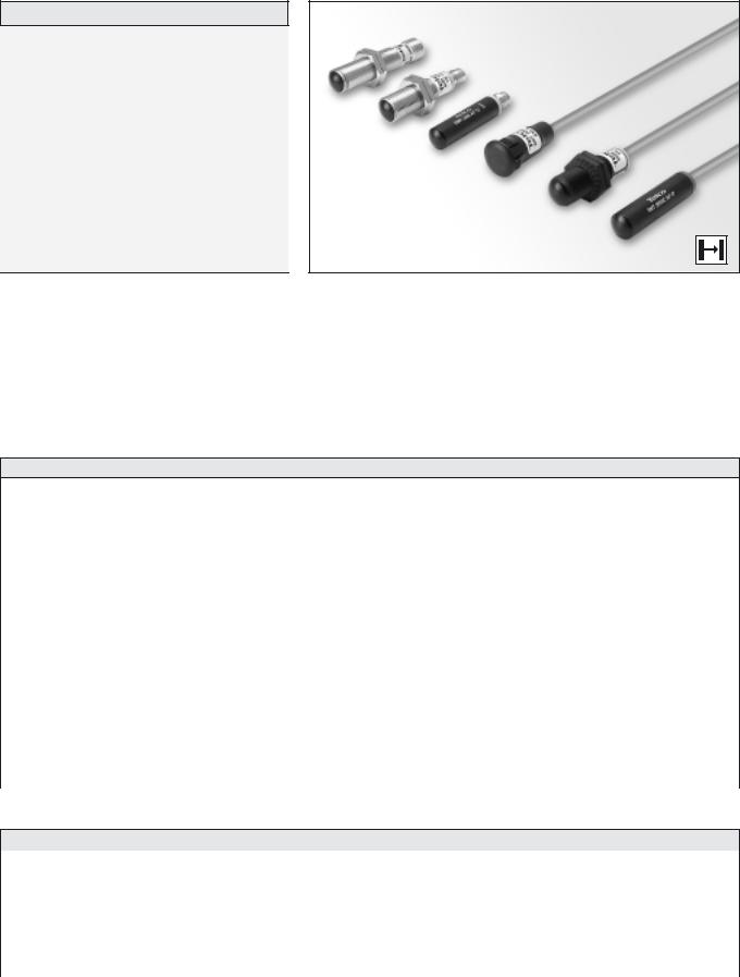
SPACEMASTER™ SERIES |
SM 3000 |
Description
Operation mode and max sensing range:
Thru beam: 1-15 m
Cable or plug connection
Sensitivity adjustment via control input
Wide variety of housings
Power and output indicator
High tolerance to hostile environments
10 – 30 V dc supply voltage
3 wire, NPN or PNP transistor output
The 3000 series consists of a self-contained transmitter SMT, and a receiver SMR, which are to be used in thru beam mode. The complete series is available in a wide range of housings with either cable or plug connection.
The SMR is supplied with a 10-30 V dc supply voltage with a 3 wire, NPN or PNP transistor output with a choice between light or dark function.
The control input in the SMT may be used for either disabling or enabling the transmitting power temporarily for test purpose, multiplexing applications or as a gradual regulation of the transmitting power level.
Both the transmitter and receiver are protected against reverse polarity of power supplies, control input and output signals. The output is also protected against short circuit and inductive loads.
Technical Data
|
|
SMT |
|
|
|
|
SMR |
|
|
|
|
|
|
|
|
|
|
|
3000C |
3012C |
3000HC |
|
3x06 |
|
3x12 |
3x15 |
|
|
|
|
|
|
|
|
|
Supply voltage |
|
|
10 – 30 V dc |
|
|
|
|
|
|
|
|
|
|
|
|
|
|
Voltage ripple |
|
|
15 % |
|
|
|
|
|
|
|
|
|
|
|
|
|
|
Reverse polarity protected |
|
|
Yes |
|
|
|
|
|
|
|
|
|
|
|
|
|
|
Short circuit protected |
|
– |
|
|
|
|
Yes |
|
|
|
|
|
|
|
|
|
|
Current consumption |
|
Max. 30 mA |
|
|
|
|
Max. 8 mA |
|
|
|
|
|
|
|
|
|
|
Maximum output load |
|
– |
|
|
|
|
100 mA |
|
|
|
|
|
|
|
|
|
|
Maximum residual voltage |
|
– |
|
|
|
|
2,5 V |
|
|
|
|
|
|
|
|
|
|
Maximum operation frequency |
|
– |
|
|
|
> 125 Hz |
> 60 Hz |
|
|
|
|
|
|
|
|
|
|
Response time tON / tOFF |
|
– |
|
|
< 4 ms / < 6 ms |
< 13 ms / < 6 ms |
||
Power on indicator |
|
Green LED |
|
|
|
|
– |
|
|
|
|
|
|
|
|
|
|
Output indicator |
|
– |
|
|
|
|
Yellow LED |
|
|
|
|
|
|
|
|
|
|
Hysteresis |
|
– |
|
|
Approx. 25 % |
Approx. 30 % |
||
|
|
|
|
|
|
|
|
|
Transmitter diode |
|
Ga Al As (880 nm) |
|
|
|
|
– |
|
|
|
|
|
|
|
|
|
|
Opening angle |
|
– |
|
|
+/– 7° |
|
+/– 3° |
+/– 7° |
|
|
|
|
|
|
|
|
|
Emission angle |
+/– 10° |
+/– 5° |
+/– 12° |
|
|
|
– |
|
|
|
|
|
|
|
|
|
|
Environmental Data
Vibration |
|
10 – 55 Hz, 0,5 mm |
|
|
||
|
|
|
|
|
|
|
Shock |
|
30 g |
|
|
|
|
|
|
|
|
|
|
|
Light immunity, @ 5° incidence |
– |
|
35 |
000 lux |
12 000 lux |
35 000 lux |
|
|
|
|
|
|
|
Temperature, operation |
|
– 20 to +50 ºC |
|
|
|
|
|
|
|
|
|
|
|
Temperature, storage |
|
– 40 to +80 ºC |
|
|
|
|
|
|
|
|
|
|
|
Sealing class |
|
IP 67 |
|
|
|
|
|
|
|
|
|
|
|
Approvals |
|
a |
|
|
|
|
|
|
|
|
|
|
|
SELF-CONTAINED PHOTOELECTRIC SYSTEMS I 67

SM 3000 |
|
|
|
|
SPACEMASTER™ SERIES |
|||||
|
|
|
|
|
|
|
|
|
|
|
Available Types |
|
|
|
|
|
|
|
|||
|
Type |
Control |
Output |
Connection |
5 m Cable |
3 pin, M8 Plug |
4 pin, M12 Plug |
Range |
||
|
|
Feature |
|
Housing Material |
Housing Type |
|
Order Reference |
|
|
|
|
|
|
|
|
|
|
|
|
|
|
Transmitter |
|
|
|
Polycarbonate |
Ø10 |
SMT 3000C AP 5 |
SMT 3000C AP T3 |
– |
|
|
|
|
|
|
|
|
|
|
|||
|
Adjustable |
|
M12 x 1 |
SMT 3000C TP 5 |
SMT 3000C TP T3 |
– |
|
|||
|
|
|
|
|||||||
3000C |
range and |
|
|
|
|
|
1- 6 m |
|||
– |
Nickel Plated Brass |
SMT 3000C TB 5 |
SMT 3000C TB T3 |
SMT 3000C TB J |
||||||
|
||||||||||
|
test input |
|
|
|||||||
|
|
|
|
|
|
|
|
|||
|
|
Polycarbonate |
Ø12,7 |
SMT 3000C S30 5* |
– |
– |
|
|||
|
|
|
|
|||||||
|
|
|
(Snap Housing) |
|
||||||
|
|
|
|
|
||||||
|
|
|
|
|
|
|
|
|
||
|
|
|
|
|
|
|
|
|
|
|
|
|
|
|
|
|
|
|
|
|
|
|
|
|
|
Polycarbonate |
Ø10 |
SMR 3006 AP 5 |
SMR 3006 AP T3 |
– |
|
|
|
|
|
|
|
|
|
|
|
||
|
|
|
NPN, NC |
M12 x 1 |
SMR 3006 TP 5 |
SMR 3006 TP T3 |
– |
|
||
|
|
|
|
|
||||||
|
3006 |
|
(light |
Nickel Plated Brass |
SMR 3006 TB 5 |
SMR 3006 TB T3 |
SMR 3006 TB J |
|
||
|
|
|
|
|||||||
|
|
|
operated) |
|
|
|
|
|
|
|
|
|
|
Polycarbonate |
Ø12,7 |
SMR 3006 S30 5*S |
– |
– |
|
||
|
|
|
|
|
||||||
|
|
|
|
(Snap Housing) |
|
|||||
|
|
|
|
|
|
|
|
|
||
|
|
|
|
|
|
|
|
|
|
|
|
|
|
|
Polycarbonate |
Ø10 |
SMR 3106 AP 5 |
SMR 3106 AP T3 |
– |
|
|
|
|
|
|
|
|
|
|
|
||
|
|
|
NPN, NO |
M12 x 1 |
SMR 3106 TP 5 |
SMR 3106 TP T3 |
– |
|
||
|
|
|
|
|
||||||
|
3106 |
|
(dark |
Nickel Plated Brass |
SMR 3106 TB 5 |
SMR 3106 TB T3 |
SMR 3106 TB J |
|
||
|
|
|
|
|||||||
|
|
|
operated) |
|
|
|
|
|
|
|
Receiver |
|
|
Polycarbonate |
Ø12,7 |
SMR 3106 S30 5*S |
– |
– |
|
||
|
|
|
|
|||||||
|
|
|
(Snap Housing) |
|
||||||
|
– |
|
|
|
|
|
6 m |
|||
|
|
|
|
|
|
|
||||
|
|
Polycarbonate |
Ø10 |
SMR 3206 AP 5 |
SMR 3206 AP T3 |
– |
||||
|
|
|
|
|||||||
|
|
|
|
|
|
|
|
|||
|
|
PNP, NC |
M12 x 1 |
SMR 3206 TP 5 |
SMR 3206 TP T3 |
– |
|
|||
|
|
|
|
|
||||||
|
3206 |
|
(light |
Nickel Plated Brass |
SMR 3206 TB 5 |
SMR 3206 TB T3 |
SMR 3206 TB J |
|
||
|
|
|
|
|||||||
|
|
|
operated) |
|
|
|
|
|
|
|
|
|
|
Polycarbonate |
Ø12,7 |
SMR 3206 S30 5*S |
– |
– |
|
||
|
|
|
|
|
||||||
|
|
|
|
(Snap Housing) |
|
|||||
|
|
|
|
|
|
|
|
|
||
|
|
|
|
|
|
|
|
|
|
|
|
|
|
|
Polycarbonate |
Ø10 |
SMR 3306 AP 5 |
SMR 3306 AP T3 |
– |
|
|
|
|
|
|
|
|
|
|
|
||
|
|
|
PNP, NO |
M12 x 1 |
SMR 3306 TP 5 |
SMR 3306 TP T3 |
– |
|
||
|
|
|
|
|
||||||
|
3306 |
|
(dark |
Nickel Plated Brass |
SMR 3306 TB 5 |
SMR 3306 TB T3 |
SMR 3306 TB J |
|
||
|
|
|
|
|||||||
|
|
|
operated) |
|
|
|
|
|
|
|
|
|
|
Polycarbonate |
Ø12,7 |
SMR 3306 S30 5*S |
– |
– |
|
||
|
|
|
|
|
||||||
|
|
|
|
(Snap Housing) |
|
|||||
|
|
|
|
|
|
|
|
|
||
|
|
|
|
|
|
|
|
|
|
|
Note: Sensors marked * do not have power on or output indicators incorporated.
Transmitter |
|
Adjustable |
|
Polycarbonate |
Ø10 |
SMT 3012C AP 5 |
SMT 3012C AP T3 |
– |
|
|
3012C |
|
|
|
|
|
|
|
|||
|
|
|
|
|
|
|
||||
range and |
– |
|
|
|
SMT 3012C TP 5 |
SMT 3012C TP T3 |
– |
2-12 m |
||
|
test input |
|
|
|
M12 x 1 |
|
|
|
|
|
|
|
Nickel Plated Brass |
SMT 3012C TB 5 |
SMT 3012C TB T3 |
SMT 3012C TB J |
|
||||
|
|
|
|
|
|
|||||
|
|
|
|
|
|
|
|
|
|
|
|
|
|
|
|
|
|
|
|
|
|
|
|
|
NPN, NC |
Polycarbonate |
Ø10 |
SMR 3012 AP 5 |
SMR 3012 AP T3 |
– |
|
|
|
3012 |
|
|
|
|
|
|
|
||
|
|
(light |
|
M12 x 1 |
SMR 3012 TP 5 |
SMR 3012 TP T3 |
– |
|
||
|
|
|
|
|
||||||
|
|
|
operated) |
|
|
|
|
|
|
|
|
|
|
Nickel Plated Brass |
|
SMR 3012 TB 5 |
SMR 3012 TB T3 |
SMR 3012 TB J |
|
||
|
|
|
|
|
|
|
||||
|
|
|
|
|
|
|
|
|
|
|
|
|
|
NPN, NO |
Polycarbonate |
Ø10 |
SMR 3112 AP 5 |
SMR 3112 AP T3 |
– |
|
|
|
3112 |
|
|
|
|
|
|
|
||
Receiver |
|
(dark |
|
M12 x 1 |
SMR 3112 TP 5 |
SMR 3112 TP T3 |
– |
|
||
|
|
|
|
|||||||
|
|
operated) |
|
|
|
|
|
|
||
|
– |
Nickel Plated Brass |
|
SMR 3112 TB 5 |
SMR 3112 TB T3 |
SMR 3112 TB J |
12 m |
|||
|
|
|
|
|||||||
|
|
|
|
|
|
|
|
|||
|
|
PNP, NC |
Polycarbonate |
Ø10 |
SMR 3212 AP 5 |
SMR 3212 AP T3 |
– |
|
||
3212 |
|
|
|
|
|
|
|
|||
|
|
|
SMR 3212 TP 5 |
SMR 3212 TP T3 |
– |
|
||||
|
|
(light |
|
|
M12 x 1 |
|
||||
|
|
|
operated) |
|
|
|
|
|
|
|
|
|
|
Nickel Plated Brass |
|
SMR 3212 TB 5 |
SMR 3212 TB T3 |
SMR 3212 TB J |
|
||
|
|
|
|
|
|
|
||||
|
|
|
|
|
|
|
|
|
|
|
|
|
|
PNP, NO |
Polycarbonate |
Ø10 |
SMR 3312 AP 5 |
SMR 3312 AP T3 |
– |
|
|
|
|
|
|
|
|
|
|
|
||
|
3312 |
|
(dark |
|
M12 x 1 |
SMR 3312 TP 5 |
SMR 3312 TP T3 |
– |
|
|
|
|
|
|
|
||||||
|
|
|
operated) |
|
|
|
|
|
|
|
|
|
|
Nickel Plated Brass |
|
SMR 3312 TB 5 |
SMR 3312 TB T3 |
SMR 3312 TB J |
|
||
|
|
|
|
|
|
|
||||
|
|
|
|
|
|
|
|
|
|
|
68 I SELF-CONTAINED PHOTOELECTRIC SYSTEMS

SPACEMASTER™ SERIES |
|
|
|
|
SM 3000 |
|||||
|
|
|
|
|
|
|
|
|
|
|
Available Types |
|
|
|
|
|
|
|
|
||
|
Type |
Control |
Output |
Connection |
5 m Cable |
3 pin, M8 Plug |
4 pin, M12 Plug |
|
Range |
|
|
|
Feature |
|
Housing Material |
Housing Type |
|
Order Reference |
|
|
|
|
|
|
|
|
|
|
|
|
|
|
Transmitter |
|
|
|
Polycarbonate |
Ø10 |
SMT 3000HC AP 5 |
SMT 3000HC AP T3 |
– |
|
|
|
|
|
|
|
|
|
|
|
||
|
Adjustable |
|
M12 x 1 |
SMT 3000HC TP 5 |
SMT 3000HC TP T3 |
– |
|
|
||
|
|
|
|
|
||||||
3000HC |
range and |
|
|
|
|
|
|
2-15 m |
||
– |
Nickel Plated Brass |
SMT 3000HC TB 5 |
SMT 3000HC TB T3 |
SMT 3000HC TB J |
|
|||||
|
|
|||||||||
|
test input |
|
|
|
||||||
|
|
|
|
|
|
|
|
|
||
|
|
Polycarbonate |
Ø12,7 |
SMT 3000HC S30 5* |
– |
– |
|
|
||
|
|
|
|
|
||||||
|
|
|
(Snap Housing) |
|
|
|||||
|
|
|
|
|
|
|||||
|
|
|
|
|
|
|
|
|
|
|
|
|
|
|
|
|
|
|
|
|
|
|
|
|
|
|
|
|
|
|
|
|
|
|
|
|
Polycarbonate |
Ø10 |
SMR 3015 AP 5 |
SMR 3015 AP T3 |
– |
|
|
|
|
|
|
|
|
|
|
|
|
|
|
|
|
NPN, NC |
M12 x 1 |
SMR 3015 TP 5 |
SMR 3015 TP T3 |
– |
|
|
|
|
|
|
|
|
|
|||||
|
3015 |
|
(light |
Nickel Plated Brass |
SMR 3015 TB 5 |
SMR 3015 TB T3 |
SMR 3015 TB J |
|
|
|
|
|
|
|
|
||||||
|
|
|
operated) |
|
|
|
|
|
|
|
|
|
|
Polycarbonate |
Ø12,7 |
SMR 3015 S30 5*S |
– |
– |
|
|
|
|
|
|
|
|
|
|||||
|
|
|
|
(Snap Housing) |
|
|
||||
|
|
|
|
|
|
|
|
|
|
|
|
|
|
|
|
|
|
|
|
|
|
|
|
|
|
Polycarbonate |
Ø10 |
SMR 3115 AP 5 |
SMR 3115 AP T3 |
– |
|
|
|
|
|
|
|
|
|
|
|
|
|
|
|
|
NPN, NO |
M12 x 1 |
SMR 3115 TP 5 |
SMR 3115 TP T3 |
– |
|
|
|
|
|
|
|
|
|
|||||
|
3115 |
|
(dark |
Nickel Plated Brass |
SMR 3115 TB 5 |
SMR 3115 TB T3 |
SMR 3115 TB J |
|
|
|
|
|
|
|
|
||||||
|
|
|
operated) |
|
|
|
|
|
|
|
Receiver |
|
|
Polycarbonate |
Ø12,7 |
SMR 3115 S30 5*S |
– |
– |
|
|
|
|
|
|
|
|
||||||
|
|
|
(Snap Housing) |
|
|
|||||
|
– |
|
|
|
|
|
|
15 m |
||
|
|
|
|
|
|
|
|
|||
|
|
Polycarbonate |
Ø10 |
SMR 3215 AP 5 |
SMR 3215 AP T3 |
– |
|
|||
|
|
|
|
|
||||||
|
|
|
|
|
|
|
|
|
||
|
|
PNP, NC |
M12 x 1 |
SMR 3215 TP 5 |
SMR 3215 TP T3 |
– |
|
|
||
|
|
|
|
|
|
|||||
|
3215 |
|
(light |
Nickel Plated Brass |
SMR 3215 TB 5 |
SMR 3215 TB T3 |
SMR 3215 TB J |
|
|
|
|
|
|
|
|
||||||
|
|
|
operated) |
|
|
|
|
|
|
|
|
|
|
Polycarbonate |
Ø12,7 |
SMR 3215 S30 5*S |
– |
– |
|
|
|
|
|
|
|
|
|
|||||
|
|
|
|
(Snap Housing) |
|
|
||||
|
|
|
|
|
|
|
|
|
|
|
|
|
|
|
|
|
|
|
|
|
|
|
|
|
|
Polycarbonate |
Ø10 |
SMR 3315 AP 5 |
SMR 3315 AP T3 |
– |
|
|
|
|
|
|
|
|
|
|
|
|
|
|
|
|
PNP, NO |
M12 x 1 |
SMR 3315 TP 5 |
SMR 3315 TP T3 |
– |
|
|
|
|
|
|
|
|
|
|||||
|
3315 |
|
(dark |
Nickel Plated Brass |
SMR 3315 TB 5 |
SMR 3315 TB T3 |
SMR 3315 TB J |
|
|
|
|
|
|
|
|
||||||
|
|
|
operated) |
|
|
|
|
|
|
|
|
|
|
Polycarbonate |
Ø12,7 |
SMR 3315 S30 5*S |
– |
– |
|
|
|
|
|
|
|
|
|
|||||
|
|
|
|
(Snap Housing) |
|
|
||||
|
|
|
|
|
|
|
|
|
|
|
|
|
|
|
|
|
|
|
|
|
|
Note: Sensors marked * do not have power on or output indicators incorporated.
Connections
|
Cable |
M8 Plug/Cable |
M12 Plug/Cable |
|
|
|
|
Supply + |
Brown |
Pin 1/Brown |
Pin 1/Brown |
|
|
|
|
Supply – |
Blue |
Pin 3/Blue |
Pin 3/Blue |
|
|
|
|
SMT control |
Black |
Pin 4/Black |
Pin 4/Black |
|
|
|
|
SMR output |
Black |
Pin 4/Black |
Pin 4/Black |
|
|
|
|
3 pin, M8 |
|
|
4 pin, M12 |
|
||
Sensor Plug |
Cable Plug |
|
Sensor Plug |
Cable Plug |
|
|
(Male) |
(Female) |
|
(Male) |
|
(Female) |
|
|
|
Black |
|
|
|
Brown |
4 |
4 |
Brown |
1 |
|
1 |
White |
2 4 |
|
4 2 |
||||
1 3 |
3 1 |
|
||||
|
|
|
3 |
|
3 |
|
|
|
Blue |
|
|
|
Blue |
|
|
|
|
|
|
Black |
SELF-CONTAINED PHOTOELECTRIC SYSTEMS I 69
SM 3000 |
SPACEMASTER™ SERIES |
Wiring Diagrams
Brown |
1 |
Brown |
1 |
|
|
200 ohm – 10 kohm |
4 |
|
|
Black |
4 |
Black |
|
|
|
|
Control |
|
|
Blue |
R |
switch |
3 |
Load |
3 |
Blue |
|
||
SMT 30xxC |
|
SMR 30xx / 31xx |
|
|
Variable range and ON/OFF switch |
|
|
|
|
for transmitting power |
|
|
|
|
|
|
Brown |
1 |
|
|
|
Black |
4 |
Load |
|
|
|
||
|
|
Blue |
3 |
|
|
|
SMR 32xx / 33xx |
|
|
Dimensions and Descriptions
|
|
41,5 |
|
|
|
|
|
38 |
|
|
58 |
|
|
26 |
LED |
|
38 |
41,5 |
LED |
|
|
|
8 |
Ø 10 |
|
M12 x 1 |
|
M12 x 1 |
M12 x 1 |
38 |
|
17 |
|
17 |
LED |
|
|
|
|||
AP 5 |
|
TP/TB 5 |
|
|
TB J |
|
|
49 |
|
|
|
|
|
38 |
|
|
32 |
49 |
|
26 |
|
|
|
|
|
|
|
||
Ø 10 |
M8 x 1 |
M12 x 1 |
M8 x 1 |
15,9 |
|
|
|
|
|
||
38 |
LED |
17 |
LED |
|
30 |
|
|
|
|||
AP T3 |
|
TP/TB T3 |
|
|
S30 5 |
(Units in mm)
70 I SELF-CONTAINED PHOTOELECTRIC SYSTEMS
SPACEMASTER™ SERIES
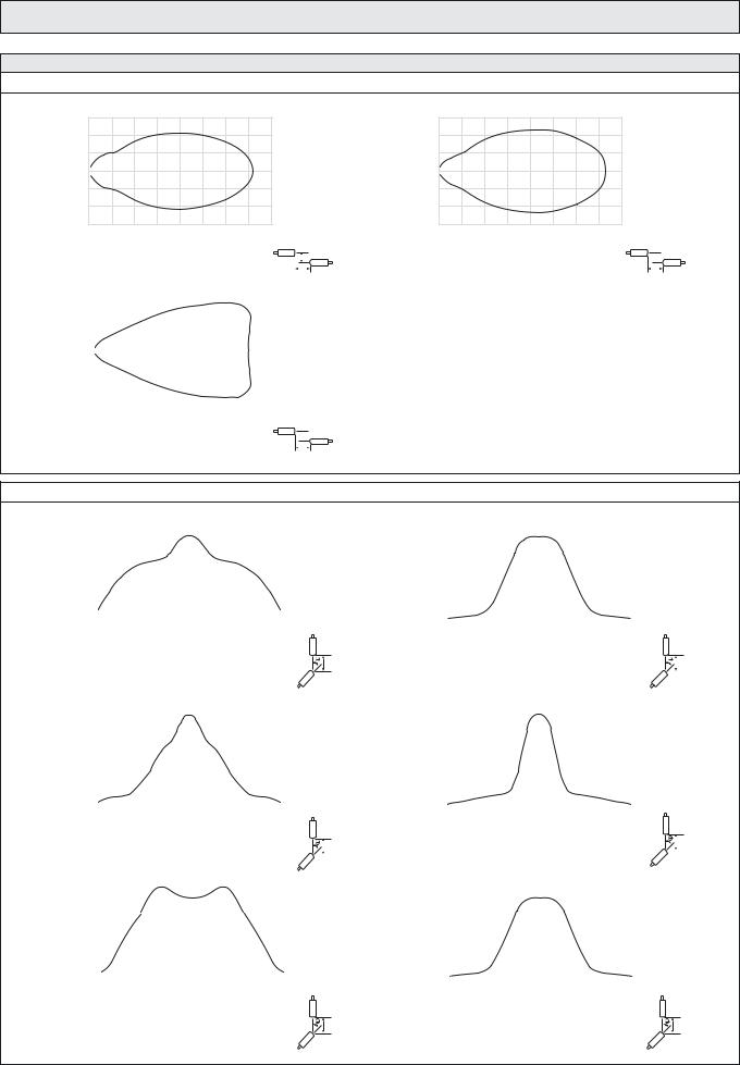
Sensing Characteristics
Parallel Displacement
|
0,6 |
|
(m) |
0,4 |
|
|
||
Displacement |
0,2 |
|
0 |
||
– 0,2 |
||
– 0,4 |
||
|
||
|
– 0,6 |
|
0 |
1 |
2 |
3 |
4 |
5 |
6 |
7 |
8 |
|
|
|
|||||
|
|
|
|
|
Range (m) |
|
|
|
|
|
|
|
|
||||
|
|
|
|
SMT 3000C and SMR 3x06 |
|
|
|
|
|
Y |
|||||||
|
|
|
|
|
|
|
|
|
|||||||||
|
|
|
|
|
|
|
|
|
|
||||||||
|
1,8 |
|
|
|
|
|
|
X |
|||||||||
|
|
|
|
|
|
|
|
|
|
|
|
|
|
|
|
|
|
|
|
|
|
|
|
|
|
|
|
|
|
|
|
|
|
|
|
(m) |
1,2 |
|
|
|
|
|
|
|
|
|
|
|
|
|
|
|
|
|
|
|
|
|
|
|
|
|
|
|
|
|
|
|
|
||
|
|
|
|
|
|
|
|
|
|
|
|
|
|
|
|
|
|
Displacement |
0,6 |
|
|
|
|
|
|
|
|
|
|
|
|
|
|
|
|
|
|
|
|
|
|
|
|
|
|
|
|
|
|
|
|
||
0 |
|
|
|
|
|
|
|
|
|
|
|
|
|
|
|
|
|
|
|
|
|
|
|
|
|
|
|
|
|
|
|
|
|
||
– 0,6 |
|
|
|
|
|
|
|
|
|
|
|
|
|
|
|
|
|
|
|
|
|
|
|
|
|
|
|
|
|
|
|
|
|
||
–1,2 |
|
|
|
|
|
|
|
|
|
|
|
|
|
|
|
|
|
|
|
|
|
|
|
|
|
|
|
|
|
|
|
|
|
|
|
|
–1,8 |
|
|
|
|
|
|
|
|
|
|
|
|
|
|
|
|
|
|
3 |
6 |
|
9 |
12 |
15 |
18 |
21 |
|
|
||||||
|
0 |
|
|
|
|||||||||||||
Range (m)
 Y
Y
SMT 3000HC and SMR 3x15 |
X |
Angular Displacement
|
8 |
|
|
|
|
|
|
|
|
|
|
|
|
|
|
|
|
|
|
|
|
|
|
|
7 |
|
|
|
|
|
|
|
|
|
|
|
|
|
|
|
|
|
|
|
|
|
|
(m) |
6 |
|
|
|
|
|
|
|
|
|
|
|
|
|
|
|
|
|
|
|
|
||
5 |
|
|
|
|
|
|
|
|
|
|
|
|
|
|
|
|
|
|
|
|
|
||
Range |
4 |
|
|
|
|
|
|
|
|
|
|
|
|
|
|
|
|
|
|
|
|
|
|
|
3 |
|
|
|
|
|
|
|
|
|
|
|
|
|
|
|
|
|
|
|
|
|
|
|
2 |
|
|
|
|
|
|
|
|
|
|
|
|
|
|
|
|
|
|
|
|
|
|
|
1 |
|
|
|
|
|
|
|
|
|
|
|
|
|
|
|
|
|
|
|
|
|
|
|
0 |
|
|
|
|
|
|
|
|
|
|
|
|
|
|
|
|
|
|
|
|
|
|
|
–20 –15 –10 –5 |
0 |
5 |
10 15 20 |
|||||||
Degrees
Y
SMT 3000C
|
16 |
|
|
|
|
|
|
|
|
|
|
|
|
|
|
|
|
|
|
|
|
|
|
|
|
|
|
|
|
|
|
|
|
|
|
|
|
|
|
|
|
|
14 |
|
|
|
|
|
|
|
|
|
|
|
|
|
|
|
|
|
|
|
|
|
|
|
|
|
|
|
|
|
|
|
|
|
|
|
|
|
|
|
|
(m) |
12 |
|
|
|
|
|
|
|
|
|
|
|
|
|
|
|
|
|
|
|
|
|
|
|
|
|
|
|
|
|
|
|
|
|
|
|
|
|
|
||
10 |
|
|
|
|
|
|
|
|
|
|
|
|
|
|
|
|
|
|
|
|
|
|
|
|
|
|
|
|
|
|
|
|
|
|
|
|
|
|
|
||
Range |
8 |
|
|
|
|
|
|
|
|
|
|
|
|
|
|
|
|
|
|
|
|
|
|
|
|
|
|
|
|
|
|
|
|
|
|
|
|
|
|
|
|
|
6 |
|
|
|
|
|
|
|
|
|
|
|
|
|
|
|
|
|
|
|
|
|
|
|
|
|
|
|
|
|
|
|
|
|
|
|
|
|
|
|
|
|
4 |
|
|
|
|
|
|
|
|
|
|
|
|
|
|
|
|
|
|
|
|
|
|
|
|
|
|
|
|
|
|
|
|
|
|
|
|
|
|
|
|
|
2 |
|
|
|
|
|
|
|
|
|
|
|
|
|
|
|
|
|
|
|
|
|
|
|
|
|
|
|
|
|
|
|
|
|
|
|
|
|
|
|
|
|
0 |
|
|
|
|
|
|
|
|
|
|
|
|
|
|
|
|
|
|
|
|
|
|
|
|
|
|
|
|
|
|
|
|
|
|
|
|
|
|
|
|
|
–20 |
–15 |
–10 |
–5 |
0 |
5 |
10 |
15 |
20 |
|
|
|||||||||
|
|
|
|
|
|
|
|
Degrees |
|
|
|
|
|
|
|
|
|
|
||
|
|
|
|
|
|
|
SMT 3012C |
|
|
|
|
|
|
|
Y |
|||||
|
|
|
|
|
|
|
|
|
|
|
|
|
|
|||||||
|
21 |
|
|
|
|
|
|
|
|
|
|
|
|
|
||||||
|
|
|
|
|
|
|
|
|
|
|
|
|
|
|
|
|
|
|
|
|
|
18 |
|
|
|
|
|
|
|
|
|
|
|
|
|
|
|
|
|
|
|
|
|
|
|
|
|
|
|
|
|
|
|
|
|
|
|
|
|
|
|
|
(m) |
15 |
|
|
|
|
|
|
|
|
|
|
|
|
|
|
|
|
|
|
|
|
|
|
|
|
|
|
|
|
|
|
|
|
|
|
|
|
|
|
||
12 |
|
|
|
|
|
|
|
|
|
|
|
|
|
|
|
|
|
|
|
|
Range |
|
|
|
|
|
|
|
|
|
|
|
|
|
|
|
|
|
|
|
|
9 |
|
|
|
|
|
|
|
|
|
|
|
|
|
|
|
|
|
|
|
|
|
|
|
|
|
|
|
|
|
|
|
|
|
|
|
|
|
|
|
||
6 |
|
|
|
|
|
|
|
|
|
|
|
|
|
|
|
|
|
|
|
|
|
|
|
|
|
|
|
|
|
|
|
|
|
|
|
|
|
|
|
|
|
|
|
|
|
|
|
|
|
|
|
|
|
|
|
|
|
|
|
|
|
|
|
3 |
|
|
|
|
|
|
|
|
|
|
|
|
|
|
|
|
|
|
|
|
|
|
|
|
|
|
|
|
|
|
|
|
|
|
|
|
|
|
|
|
|
0 |
|
|
|
|
|
|
|
|
|
|
|
|
|
|
|
|
|
|
|
|
|
|
|
|
|
|
|
|
|
|
|
|
|
|
|
|
|
|
|
|
|
–20 |
–15 |
–10 |
–5 |
0 |
5 |
10 |
15 |
20 |
|
|
|||||||||
Degrees
Y
SMT 3000HC
Telco reserves the right to change specifications without notice.
SM 3000
|
0,6 |
(m) |
0,4 |
|
|
Displacement |
0,2 |
|
0
– 0,2
– 0,4
– 0,6
0 |
2 |
4 |
6 |
8 |
10 |
12 |
14 |
16 |
|
|
|
Range (m) |
|
|
|
||
 Y
Y
SMT 3012 and SMR 3x12 |
X |
|
8 |
|
|
|
|
|
|
|
|
|
|
|
|
|
|
|
|
|
|
|
|
|
|
|
|
|
|
|
|
|
|
|
|
|
|
|
|
|
|
|
|
|
7 |
|
|
|
|
|
|
|
|
|
|
|
|
|
|
|
|
|
|
|
|
|
|
|
|
|
|
|
|
|
|
|
|
|
|
|
|
|
|
|
|
(m) |
6 |
|
|
|
|
|
|
|
|
|
|
|
|
|
|
|
|
|
|
|
|
|
|
|
|
|
|
|
|
|
|
|
|
|
|
|
|
|
|
||
5 |
|
|
|
|
|
|
|
|
|
|
|
|
|
|
|
|
|
|
|
|
|
|
|
|
|
|
|
|
|
|
|
|
|
|
|
|
|
|
|
||
Range |
4 |
|
|
|
|
|
|
|
|
|
|
|
|
|
|
|
|
|
|
|
|
|
|
|
|
|
|
|
|
|
|
|
|
|
|
|
|
|
|
|
|
|
3 |
|
|
|
|
|
|
|
|
|
|
|
|
|
|
|
|
|
|
|
|
|
|
|
|
|
|
|
|
|
|
|
|
|
|
|
|
|
|
|
|
|
2 |
|
|
|
|
|
|
|
|
|
|
|
|
|
|
|
|
|
|
|
|
|
|
|
|
|
|
|
|
|
|
|
|
|
|
|
|
|
|
|
|
|
1 |
|
|
|
|
|
|
|
|
|
|
|
|
|
|
|
|
|
|
|
|
|
|
|
|
|
|
|
|
|
|
|
|
|
|
|
|
|
|
|
|
|
0 |
|
|
|
|
|
|
|
|
|
|
|
|
|
|
|
|
|
|
|
|
|
|
|
|
|
|
|
|
|
|
|
|
|
|
|
|
|
|
|
|
|
–20 |
–15 |
–10 |
–5 |
0 |
5 |
10 |
15 |
20 |
|
|
|||||||||
|
|
|
|
|
|
|
|
Degrees |
|
|
|
|
|
|
|
|
|
Y |
||
|
|
|
|
|
|
|
|
SMR 3x06 |
|
|
|
|
|
|
|
|||||
|
16 |
|
|
|
|
|
|
|
|
|
|
|
|
|
|
|||||
|
|
|
|
|
|
|
|
|
|
|
|
|
|
|
||||||
|
|
|
|
|
|
|
|
|
|
|
|
|
|
|
|
|
|
|
|
|
|
14 |
|
|
|
|
|
|
|
|
|
|
|
|
|
|
|
|
|
|
|
|
|
|
|
|
|
|
|
|
|
|
|
|
|
|
|
|
|
|
|
|
(m) |
12 |
|
|
|
|
|
|
|
|
|
|
|
|
|
|
|
|
|
|
|
|
|
|
|
|
|
|
|
|
|
|
|
|
|
|
|
|
|
|
||
10 |
|
|
|
|
|
|
|
|
|
|
|
|
|
|
|
|
|
|
|
|
|
|
|
|
|
|
|
|
|
|
|
|
|
|
|
|
|
|
|
||
Range |
8 |
|
|
|
|
|
|
|
|
|
|
|
|
|
|
|
|
|
|
|
|
|
|
|
|
|
|
|
|
|
|
|
|
|
|
|
|
|
|
|
|
|
6 |
|
|
|
|
|
|
|
|
|
|
|
|
|
|
|
|
|
|
|
|
|
|
|
|
|
|
|
|
|
|
|
|
|
|
|
|
|
|
|
|
|
4 |
|
|
|
|
|
|
|
|
|
|
|
|
|
|
|
|
|
|
|
|
|
|
|
|
|
|
|
|
|
|
|
|
|
|
|
|
|
|
|
|
|
2 |
|
|
|
|
|
|
|
|
|
|
|
|
|
|
|
|
|
|
|
|
|
|
|
|
|
|
|
|
|
|
|
|
|
|
|
|
|
|
|
|
|
0 |
|
|
|
|
|
|
|
|
|
|
|
|
|
|
|
|
|
|
|
|
|
|
|
|
|
|
|
|
|
|
|
|
|
|
|
|
|
|
|
|
|
–20 |
–15 |
–10 |
–5 |
0 |
5 |
10 |
15 |
20 |
|
|
|||||||||
|
|
|
|
|
|
|
|
Degrees |
|
|
|
|
|
|
|
|
|
Y |
||
|
|
|
|
|
|
|
|
SMR 3x12 |
|
|
|
|
|
|
|
|
|
|||
|
21 |
|
|
|
|
|
|
|
|
|
|
|
|
|
|
|
|
|||
|
|
|
|
|
|
|
|
|
|
|
|
|
|
|
|
|
||||
|
|
|
|
|
|
|
|
|
|
|
|
|
|
|
|
|
|
|
|
|
|
18 |
|
|
|
|
|
|
|
|
|
|
|
|
|
|
|
|
|
|
|
|
|
|
|
|
|
|
|
|
|
|
|
|
|
|
|
|
|
|
|
|
(m) |
15 |
|
|
|
|
|
|
|
|
|
|
|
|
|
|
|
|
|
|
|
|
|
|
|
|
|
|
|
|
|
|
|
|
|
|
|
|
|
|
||
12 |
|
|
|
|
|
|
|
|
|
|
|
|
|
|
|
|
|
|
|
|
Range |
|
|
|
|
|
|
|
|
|
|
|
|
|
|
|
|
|
|
|
|
9 |
|
|
|
|
|
|
|
|
|
|
|
|
|
|
|
|
|
|
|
|
|
|
|
|
|
|
|
|
|
|
|
|
|
|
|
|
|
|
|
|
|
|
6 |
|
|
|
|
|
|
|
|
|
|
|
|
|
|
|
|
|
|
|
|
|
|
|
|
|
|
|
|
|
|
|
|
|
|
|
|
|
|
|
|
|
3 |
|
|
|
|
|
|
|
|
|
|
|
|
|
|
|
|
|
|
|
|
|
|
|
|
|
|
|
|
|
|
|
|
|
|
|
|
|
|
|
|
|
0 |
|
|
|
|
|
|
|
|
|
|
|
|
|
|
|
|
|
|
|
|
|
|
|
|
|
|
|
|
|
|
|
|
|
|
|
|
|
|
|
|
|
–20 |
–15 |
–10 |
–5 |
0 |
5 |
10 |
15 |
20 |
|
|
|||||||||
Degrees
Y
SMR 3x15
SELF-CONTAINED PHOTOELECTRIC SYSTEMS I 71
SPACEMASTER™ SERIES |
SM 6000 |
Description
Operation mode and max sensing range:
Thru beam: 1-6 m
Cable or plug connection
Sensitivity adjustment via control input
Wide variety of housings
Power and output indicators
High tolerance to hostile environments
10 – 32 V dc supply voltage
3 wire, NPN or PNP output or
4 wire, NPN/PNP opto isolated output
5 or 0,5 ms response time
Low current consumption
The 6000 series consists of a self-contained transmitter SMT, and a receiver SMR, which are to be used in thru beam mode. The complete series is available in a wide range of housings with either plug or cable connection.
The SMR is supplied with a 10-32 V dc supply voltage with either a 3 wire, NPN or PNP or as a 4 wire, NPN/PNP opto-isolated transistor output with a choice between light or dark function. The SMR is available with either a 0.5 ms response time with a 2 metre range, or with a 5 ms
response time with a 6 metre range. The control input in the SMT may be used for either disabling or enabling the transmitting power temporarily for test purpose, multiplexing applications or as a gradual regulation of the transmitting power level.
Both the transmitter and receiver are protected against reverse polarity of power supplies, control input and output signals. The output is also protected against short circuit and inductive loads.
Technical Data
|
SMT |
|
SMR |
|
|
|
|
|
|
|
|
6x02 |
|
6x06 |
|
|
|
|
|
Supply voltage |
|
10 – 32 V dc |
|
|
|
|
|
|
|
Voltage ripple |
|
15 % |
|
|
|
|
|
|
|
Reverse polarity protected |
|
Yes |
|
|
|
|
|
|
|
Short circuit protected |
– |
|
Yes |
|
|
|
|
|
|
Current consumption |
|
max. 320 mW |
|
|
|
|
|
|
|
Maximum output load |
– |
|
100 mA |
|
|
|
|
|
|
Maximum residual voltage |
– |
|
2,5 V |
|
|
|
|
|
|
Maximum operation frequency |
– |
1000 Hz |
|
100 Hz |
|
|
|
|
|
Response time tON / tOFF |
– |
0,5 ms / 0,5 ms |
|
5 ms / 5 ms |
Power on indicator |
Green LED |
|
– |
|
|
|
|
|
|
Output indicator |
– |
|
Yellow LED |
|
|
|
|
|
|
Hysteresis |
– |
|
Approx. 30% |
|
|
|
|
|
|
Transmitter diode |
Ga Al As (880 nm) |
|
– |
|
|
|
|
|
|
Opening angle |
– |
|
+/– 6° |
|
|
|
|
|
|
Emission angle |
+/– 10° |
|
– |
|
|
|
|
|
|
Environmental Data
Vibration |
|
10 – 55 Hz, 0,5 mm |
|
|
|
Shock |
|
30 g |
|
|
|
Light immunity, @ 5° incidence |
– |
> 50 000 lux |
|
|
|
Temperature, operation |
|
– 20 to +60 ºC |
|
|
|
Temperature, storage |
|
– 40 to +80 ºC |
|
|
|
Sealing class |
|
IP 67 |
|
|
|
Approvals |
|
a |
|
|
|
SELF-CONTAINED PHOTOELECTRIC SYSTEMS I 73

SM 6000 |
|
|
|
|
|
SPACEMASTER™ SERIES |
||||
|
|
|
|
|
|
|
|
|
|
|
Available Types |
|
|
|
|
|
|
|
|
||
|
Type |
Control |
Output |
Connection |
5 m Cable |
3 pin, M8 Plug |
4 pin, M8 Plug |
4 pin, M12 Plug |
Range |
|
|
|
Feature |
|
Housing Material |
Housing Type |
|
Order Reference |
|
|
|
|
|
|
|
|
|
|
|
|
|
|
Transmitter |
|
|
|
Polycarbonate |
Ø10 |
SMT 6000 AP 5 |
SMT 6000 AP T3 |
– |
– |
|
|
|
|
|
|
|
|
|
|
||
|
Adjustable |
|
M12 x 1 |
SMT 6000 TP 5 |
SMT 6000 TP T3 |
– |
– |
|
||
|
|
|
|
|||||||
|
|
|
|
|
|
|
|
|
||
6000 |
range and |
– |
Stainless Steel |
Ø10 |
SMT 6000 AS 5 |
SMT 6000 AS T3 |
SMT 6000 AS T4 |
– |
1– 6 m |
|
|
test input |
|
|
|
|
|
|
|
||
|
|
M12 x 1 |
SMT 6000 TS 5 |
SMT 6000 TS T3 |
SMT 6000 TS T4 |
SMT 6000 TS J |
|
|||
|
|
|
|
|||||||
|
|
|
|
|
||||||
|
|
|
|
|
|
|
|
|
|
|
|
|
|
|
Polyester |
9,5 x 11,5 |
SMT 6000 SG 5* |
SMT 6000 SG T3 |
– |
– |
|
|
|
|
|
|
|
|
|
|
|
|
|
|
|
|
|
|
|
|
|
|
|
|
|
|
|
Polycarbonate |
Ø10 |
SMR 6006 AP 5 |
SMR 6006 AP T3 |
– |
– |
|
|
|
|
|
|
|
|
|
|
|
|
|
|
|
NPN, NC |
M12 x 1 |
SMR 6006 TP 5 |
SMR 6006 TP T3 |
– |
– |
|
|
|
|
|
|
|
||||||
|
|
|
|
|
|
|
|
|
|
|
|
6006 |
|
(light |
Stainless Steel |
Ø10 |
SMR 6006 AS 5 |
SMR 6006 AS T3 |
– |
– |
|
|
|
|
operated) |
|
|
|
|
|
|
|
|
|
|
M12 x 1 |
SMR 6006 TS 5 |
SMR 6006 TS T3 |
– |
SMR 6006 TS J |
|
||
|
|
|
|
|
||||||
|
|
|
|
|
|
|||||
|
|
|
|
|
|
|
|
|
|
|
|
|
|
|
Polyester |
9,5 x 11,5 |
SMR 6006 SG 5* |
SMR 6006 SG T3 |
– |
– |
|
|
|
|
|
|
|
|
|
|
|
|
|
|
|
|
Polycarbonate |
Ø10 |
SMR 6106 AP 5 |
SMR 6106 AP T3 |
– |
– |
|
|
|
|
|
|
|
|
|
|
|
|
|
|
|
NPN, NO |
M12 x 1 |
SMR 6106 TP 5 |
SMR 6106 TP T3 |
– |
– |
|
|
|
|
|
|
|
||||||
|
6106 |
|
|
|
|
|
|
|
|
|
|
|
(dark |
Stainless Steel |
Ø10 |
SMR 6106 AS 5 |
SMR 6106 AS T3 |
– |
– |
|
|
|
|
|
operated) |
|
|
|
|
|
|
|
|
|
|
M12 x 1 |
SMR 6106 TS 5 |
SMR 6106 TS T3 |
– |
SMR 6106 TS J |
|
||
|
|
|
|
|
||||||
|
|
|
|
|
|
|||||
|
|
|
|
|
|
|
|
|
|
|
|
|
|
|
Polyester |
9,5 x 11,5 |
SMR 6106 SG 5* |
SMR 6106 SG T3 |
– |
– |
|
|
|
|
|
Polycarbonate |
Ø10 |
SMR 6206 AP 5 |
SMR 6206 AP T3 |
– |
– |
|
|
|
|
|
|
|
|
|
|
|
|
|
|
|
PNP, NC |
M12 x 1 |
SMR 6206 TP 5 |
SMR 6206 TP T3 |
– |
– |
|
|
|
|
|
|
|
||||||
Receiver |
6206 |
|
|
|
|
|
|
|
|
|
|
(light |
Stainless Steel |
Ø10 |
SMR 6206 AS 5 |
SMR 6206 AS T3 |
– |
– |
|
||
|
– |
operated) |
|
|
|
|
|
6 m |
||
|
M12 x 1 |
SMR 6206 TS 5 |
SMR 6206 TS T3 |
– |
SMR 6206 TS J |
|||||
|
|
|||||||||
|
|
|
|
|
||||||
|
|
|
|
|
|
|
|
|
|
|
|
|
|
Polyester |
9,5 x 11,5 |
SMR 6206 SG 5* |
SMR 6206 SG T3 |
– |
– |
|
|
|
|
|
|
|
||||||
|
|
|
|
|
|
|
|
|
|
|
|
|
|
|
Polycarbonate |
Ø10 |
SMR 6306 AP 5 |
SMR 6306 AP T3 |
– |
– |
|
|
|
|
|
|
|
|
|
|
|
|
|
|
|
PNP, NO |
M12 x 1 |
SMR 6306 TP 5 |
SMR 6306 TP T3 |
– |
– |
|
|
|
|
|
|
|
||||||
|
6306 |
|
|
|
|
|
|
|
|
|
|
|
(dark |
Stainless Steel |
Ø10 |
SMR 6306 AS 5 |
SMR 6306 AS T3 |
– |
– |
|
|
|
|
|
operated) |
|
|
|
|
|
|
|
|
|
|
M12 x 1 |
SMR 6306 TS 5 |
SMR 6306 TS T3 |
– |
SMR 6306 TS J |
|
||
|
|
|
|
|
||||||
|
|
|
|
|
|
|||||
|
|
|
|
|
|
|
|
|
|
|
|
|
|
|
Polyester |
9,5 x 11,5 |
SMR 6306 SG 5* |
SMR 6306 SG T3 |
– |
– |
|
|
|
|
|
|
|
|
|
|
|
|
|
|
|
NPN/PNP, |
|
Ø10 |
– |
– |
SMR 6406 AS T4 |
– |
|
|
|
|
NO |
|
|
|||||
|
6406 |
|
|
|
|
|
|
|
|
|
|
|
(dark |
|
|
|
|
SMR 6406 TS T4 |
SMR 6406 TS J |
|
|
|
|
|
|
|
|
|
|
|||
|
|
|
operated) |
|
M12 x 1 |
– |
– |
|
||
|
|
|
|
Stainless Steel |
|
|
|
|
|
|
|
|
|
NPN/PNP, |
Ø10 |
– |
– |
SMR 6506 AS T4 |
– |
|
|
|
|
|
|
|
||||||
|
|
|
NC |
|
|
|||||
|
6506 |
|
|
|
|
|
|
|
|
|
|
|
(light |
|
M12 x 1 |
– |
– |
SMR 6506 TS T4 |
SMR 6506 TS J |
|
|
|
|
|
|
|
||||||
|
|
|
operated) |
|
|
|||||
|
|
|
|
|
|
|
|
|
|
|
Note: Sensors marked * do not have power on or output indicators incorporated.
74 I SELF-CONTAINED PHOTOELECTRIC SYSTEMS
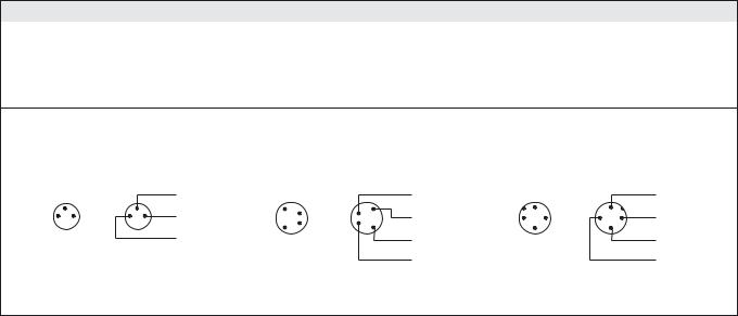
SPACEMASTER™ SERIES |
|
|
|
|
SM 6000 |
|||||||
|
|
|
|
|
|
|
|
|
|
|
|
|
|
Type |
Control |
Output |
Connection |
5m Cable |
3 pin, M8 Plug |
4 pin, M8 Plug |
4 pin, M12 Plug |
Range |
|||
|
Feature |
Housing Material |
Housing Type |
|
Order Reference |
|
|
|
||||
|
|
|
|
|
|
|
|
|||||
|
|
|
|
|
|
|
|
|
|
|
||
|
|
|
|
Polycarbonate |
Ø10 |
SMR 6002 AP 5 |
SMR 6002 AP T3 |
– |
– |
|
||
|
|
|
|
|
|
|
|
|
|
|
||
|
|
|
NPN, NC |
M12 x 1 |
SMR 6002 TP 5 |
SMR 6002 TP T3 |
– |
– |
|
|||
|
|
|
|
|
||||||||
|
|
|
|
|
|
|
|
|
|
|
||
|
6002 |
|
(light |
Stainless Steel |
Ø10 |
SMR 6002 AS 5 |
SMR 6002 AS T3 |
– |
– |
|
||
|
|
|
operated) |
|
|
|
|
|
|
|
||
|
|
|
M12 x 1 |
SMR 6002 TS 5 |
SMR 6002 TS T3 |
– |
SMR 6002 TS J |
|
||||
|
|
|
|
|
||||||||
|
|
|
|
|
|
|||||||
|
|
|
|
|
|
|
|
|
|
|
|
|
|
|
|
|
Polyester |
9,5 x 11,5 |
SMR 6002 SG 5* |
SMR 6002 SG T3 |
– |
– |
|
||
|
|
|
|
|
|
|
|
|
|
|
|
|
|
|
|
|
Polycarbonate |
Ø10 |
SMR 6102 AP 5 |
SMR 6102 AP T3 |
– |
– |
|
||
|
|
|
|
|
|
|
|
|
|
|
||
|
|
|
NPN, NO |
M12 x 1 |
SMR 6102 TP 5 |
SMR 6102 TP T3 |
– |
– |
|
|||
|
|
|
|
|
||||||||
|
|
|
|
|
|
|
|
|
|
|
||
|
6102 |
|
(dark |
Stainless Steel |
Ø10 |
SMR 6102 AS 5 |
SMR 6102 AS T3 |
– |
– |
|
||
|
|
|
operated) |
|
|
|
|
|
|
|
||
|
|
|
M12 x 1 |
SMR 6102 TS 5 |
SMR 6102 TS T3 |
– |
SMR 6102 TS J |
|
||||
|
|
|
|
|
||||||||
|
|
|
|
|
|
|||||||
|
|
|
|
|
|
|
|
|
|
|
|
|
|
|
|
|
Polyester |
9,5 x 11,5 |
SMR 6102 SG 5* |
SMR 6102 SG T3 |
– |
– |
|
||
|
|
|
|
|
|
|
|
|
|
|
|
|
|
|
|
|
Polycarbonate |
Ø10 |
SMR 6202 AP 5 |
SMR 6202 AP T3 |
– |
– |
|
||
|
|
|
|
|
|
|
|
|
|
|
||
|
|
|
PNP, NC |
M12 x 1 |
SMR 6202 TP 5 |
SMR 6202 TP T3 |
– |
– |
2 m |
|||
|
|
|
|
|||||||||
Receiver |
|
|
|
|
|
|
|
|
|
|||
6202 |
– |
(light |
Stainless Steel |
Ø10 |
SMR 6202 AS 5 |
SMR 6202 AS T3 |
– |
– |
||||
|
||||||||||||
|
|
operated) |
|
|
|
|
|
|
|
|||
|
|
M12 x 1 |
SMR 6202 TS 5 |
SMR 6202 TS T3 |
– |
SMR 6202 TS J |
|
|||||
|
|
|
|
|||||||||
|
|
|
|
|
||||||||
|
|
|
|
|
|
|
|
|
|
|
||
|
|
|
Polyester |
9,5 x 11,5 |
SMR 6202 SG 5* |
SMR 6202 SG T3 |
– |
– |
|
|||
|
|
|
|
|
||||||||
|
|
|
|
|
|
|
|
|
|
|
|
|
|
|
|
|
Polycarbonate |
Ø10 |
SMR 6302 AP 5 |
SMR 6302 AP T3 |
– |
– |
|
||
|
|
|
|
|
|
|
|
|
|
|
||
|
|
|
PNP, NO |
M12 x 1 |
SMR 6302 TP 5 |
SMR 6302 TP T3 |
– |
– |
|
|||
|
|
|
|
|
||||||||
|
|
|
|
|
|
|
|
|
|
|
||
|
6302 |
|
(dark |
Stainless Steel |
Ø10 |
SMR 6302 AS 5 |
SMR 6302 AS T3 |
– |
– |
|
||
|
|
|
operated) |
|
|
|
|
|
|
|
||
|
|
|
M12 x 1 |
SMR 6302 TS 5 |
SMR 6302 TS T3 |
– |
SMR 6302 TS J |
|
||||
|
|
|
|
|
||||||||
|
|
|
|
|
|
|||||||
|
|
|
|
|
|
|
|
|
|
|
|
|
|
|
|
|
Polyester |
9,5 x 11,5 |
SMR 6302 SG 5* |
SMR 6302 SG T3 |
– |
– |
|
||
|
|
|
|
|
|
|
|
|
|
|
|
|
|
|
|
NPN/PNP, |
|
Ø10 |
– |
– |
SMR 6402 AS T4 |
SMR 6402 AS J |
|
||
|
6402 |
|
NO |
|
|
|||||||
|
|
|
|
|
|
|
|
|
|
|||
|
|
|
(dark |
|
M12 x 1 |
– |
– |
SMR 6402 TS T4 |
SMR 6402 TS J |
|
||
|
|
|
operated) |
|
|
|||||||
|
|
|
|
Stainless Steel |
|
|
|
|
|
|
|
|
|
|
|
NPN/PNP, |
Ø10 |
– |
– |
SMR 6502 AS T4 |
SMR 6502 AS J |
|
|||
|
|
|
|
|
||||||||
|
6502 |
|
NC |
|
|
|||||||
|
|
|
|
|
|
|
|
|
|
|||
|
|
|
(light |
|
M12 x 1 |
– |
– |
SMR 6502 TS T4 |
SMR 6502 TS J |
|
||
|
|
|
operated) |
|
|
|||||||
|
|
|
|
|
|
|
|
|
|
|
|
|
Note: Sensors marked * do not have power on or output indicators incorporated.
Connections
|
Cable |
M8 Plug/Cable |
M12 Plug/Cable |
|
|
|
|
Supply + |
Brown |
Pin 1/Brown |
Pin 1/Brown |
|
|
|
|
Supply – |
Blue |
Pin 3/Blue |
Pin 3/Blue |
|
|
|
|
Control/output |
Black |
Pin 4/Black |
Pin 4/Black |
|
|
|
|
SMR output |
White |
Pin 2/White |
Pin 2/White |
|
|
|
|
3 pin, M8 |
4 pin, M8 |
4 pin, M12 |
|||
Sensor Plug |
Cable Plug |
Sensor Plug |
Cable Plug |
Sensor Plug |
Cable Plug |
(Male) |
(Female) |
(Male) |
(Female) |
(Male) |
(Female) |
|
Black |
|
White |
|
Brown |
|
4 |
|
4 |
1 |
3 |
3 |
1 |
Brown
1 |
1 |
2 |
2 |
4 |
4 |
3 |
3 |
Brown
|
1 |
|
1 |
2 |
4 |
4 |
2 |
|
3 |
|
3 |
White
Blue |
Blue |
Blue |
|
Black |
Black |
SELF-CONTAINED PHOTOELECTRIC SYSTEMS I 75
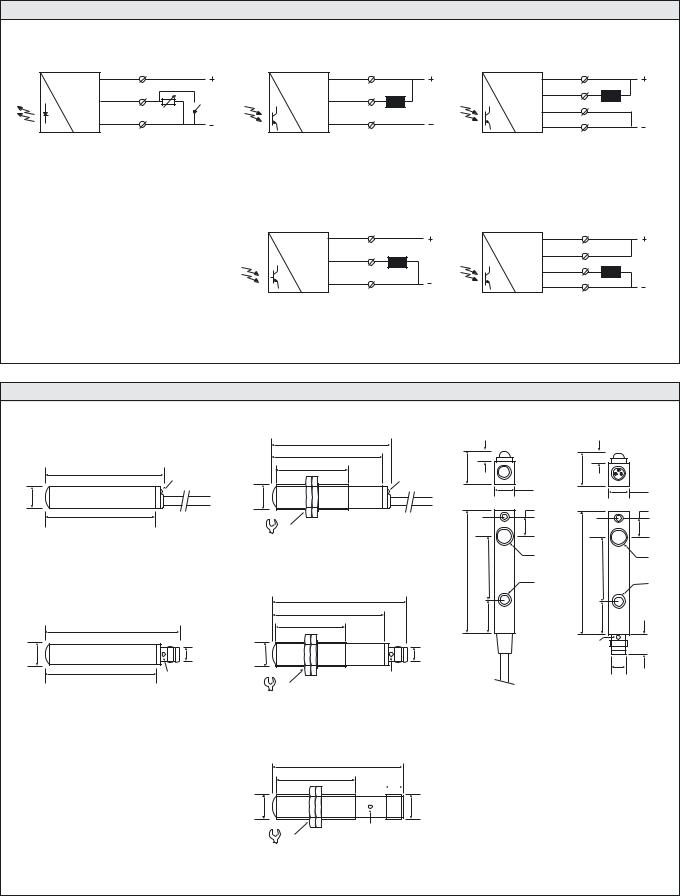
SM 6000 |
SPACEMASTER™ SERIES |
Wiring Diagrams |
|
|
|
|
|
|
|
Brown |
1 |
Brown |
1 |
|
Brown |
1 |
|
|
2 - 20 kohm |
|
|
Load |
White |
2 |
Load |
Black |
4 |
Black |
4 |
|
|
|
|
|
|
|
|
||||
|
R |
Control |
|
|
Black |
4 |
|
Blue |
switch |
3 |
|
|
|
|
|
3 |
Blue |
|
Blue |
3 |
|
||
|
|
|
|
|
|
||
SMT 6000 1-6 m |
|
SMR 600x / 610x |
|
|
SMR 640x / 650x (load as NPN) |
|
|
Variable range and ON/OFF switch |
|
|
|
|
|
|
|
for transmitting power |
|
|
|
|
|
|
|
|
|
Brown |
1 |
|
Brown |
1 |
|
|
|
Black |
4 |
Load |
White |
2 |
|
|
|
|
|
|
|||
|
|
|
|
|
|
||
|
|
|
|
|
Black |
4 |
|
|
|
Blue |
3 |
|
Blue |
3 |
Load |
|
|
|
|
|
|||
|
|
SMR 620x / 630x |
|
|
SMR 640x / 650x (load as PNP) |
|
|
Dimensions and Descriptions
|
|
|
|
60 |
|
|
|
|
|
|
|
|
54 |
|
5 |
|
5 |
|
|
|
|
35 |
|
|
||
|
60 |
|
|
16 |
|
16 |
|
|
|
|
|
|
|
|
|||
|
|
LED |
|
|
LED |
|
|
|
Ø 10 |
|
|
M12 x 1 |
|
|
10 |
|
10 |
|
|
|
|
|
|
|
||
|
|
|
|
|
|
8,7 |
|
8,7 |
|
54 |
|
|
17 |
|
|
|
|
|
|
|
|
|
|
|
|
|
|
AP/AS 5 |
|
|
TP/TS 5 |
|
|
|
|
|
|
|
|
|
|
Ø 9 |
|
Ø 9 |
|
|
|
|
|
60 |
32,3 |
60 |
32,3 |
|
|
|
|
|
|
Ø 3,5 |
|
Ø 3,5 |
|
|
|
|
66 |
|
|
|
|
|
|
|
|
55 |
|
15 |
|
15 |
|
|
|
|
34 |
|
|
||
|
66 |
|
|
|
|
|
9 |
|
|
|
|
|
|
|
|
||
|
|
|
|
|
|
|
|
|
|
|
|
|
|
|
|
|
LED |
Ø 10 |
|
M8 x 1 |
M12 x 1 |
|
M8 x 1 |
|
|
|
|
|
LED |
|
|
|
|
|
M8 x 1 |
|
55 |
|
17 |
LED |
|
|
|
|
|
|
|
|
|
|
|
||
|
|
|
|
|
|
|
|
|
|
AP/AS T3/T4 |
|
|
TP/TS T3/T4 |
|
SG 5 |
|
SG T3 |
|
|
|
|
|
|
|
64
38


 8
8
M12 x 1 |
M12 x 1 |
LED
17
TS J
(Units in mm)
76 I SELF-CONTAINED PHOTOELECTRIC SYSTEMS
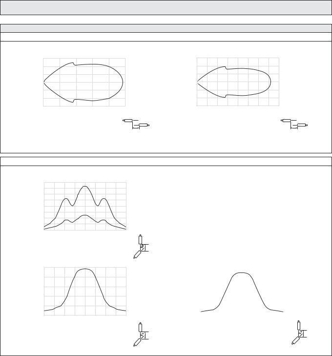
SPACEMASTER™ SERIES
Sensing Characteristics
Parallel Displacement
|
0,15 |
(m) |
0,10 |
|
|
Displacement |
0,05 |
|
|
|
0 |
–0,05
–0,10
–0,15
0 |
0,5 |
1,0 |
1,5 |
2,0 |
2,5 |
Range (m)
 Y
Y
X
SMT 6000 and SMR 6x02
Angular Displacement
|
8 |
|
|
7 |
|
(m) |
6 |
|
5 |
|
|
Range |
4 |
SMR 6x06 |
|
||
|
3 |
|
|
2 |
|
|
1 |
SMR 6x02 |
|
0 |
|
|
–20 –15 –10 |
–5 0 5 10 15 20 |
|
|
Degrees |
|
|
Y |
|
|
SMT 6000 |
|
2,5 |
|
|
2,0 |
|
(m) |
1,5 |
|
Range |
|
|
1,0 |
|
|
|
|
|
|
0,5 |
|
0
–20 –15 –10 –5 0 5 10 15 20 Degrees
Y
SMR 6x02
Telco reserves the right to change specifications without notice.
SM 6000
|
0,6 |
(m) |
0,4 |
|
|
Displacement |
0,2 |
|
|
|
0 |
– 0,2
– 0,4
– 0,6
0 |
1 |
2 |
3 |
4 |
5 |
6 |
7 |
8 |
|
|
|
Range (m) |
|
|
|
||
 Y
Y
X
SMT 6000 and SMR 6x06
|
8 |
|
|
|
|
|
|
|
|
|
|
|
|
|
|
|
|
|
|
|
|
|
|
|
7 |
|
|
|
|
|
|
|
|
|
|
|
|
|
|
|
|
|
|
|
|
|
|
(m) |
6 |
|
|
|
|
|
|
|
|
|
|
|
|
|
|
|
|
|
|
|
|
||
5 |
|
|
|
|
|
|
|
|
|
|
|
|
|
|
|
|
|
|
|
|
|
||
Range |
4 |
|
|
|
|
|
|
|
|
|
|
|
|
|
|
|
|
|
|
|
|
|
|
|
3 |
|
|
|
|
|
|
|
|
|
|
|
|
|
|
|
|
|
|
|
|
|
|
|
2 |
|
|
|
|
|
|
|
|
|
|
|
|
|
|
|
|
|
|
|
|
|
|
|
1 |
|
|
|
|
|
|
|
|
|
|
|
|
|
|
|
|
|
|
|
|
|
|
|
0 |
|
|
|
|
|
|
|
|
|
|
|
|
|
|
|
|
|
|
|
|
|
|
|
–20 –15 –10 –5 |
0 |
5 |
10 15 20 |
|||||||
Degrees
Y
SMR 6x06
SELF-CONTAINED PHOTOELECTRIC SYSTEMS I 77
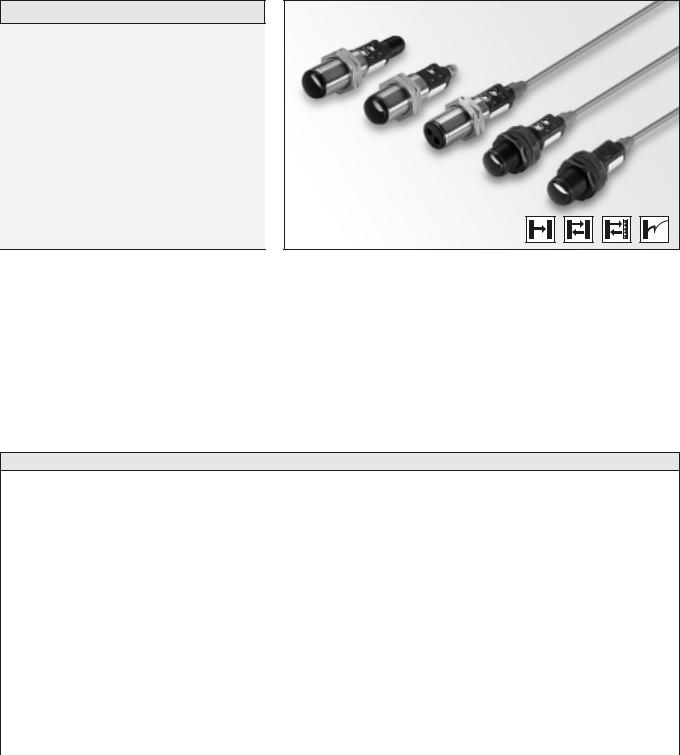
SPACEMASTER™ SERIES |
SM 7000 |
Description
Operation mode and max sensing range:
Thru beam: 0-20 m Diffuse proximity: 0-0,5 m Retro reflective: 0-3 m
Fibre: Dependent on fibre optic
Cable or plug connection
Sensitivity adjustment via potentiometer
Switch selectable light or dark function
Power and output indicators
High tolerance to hostile environments
10-30 V dc supply voltage
4 wire, NPN/PNP transistor output or 4 wire, ambivalent PNP/PNP transistor output
Test input
The 7000 series consists of a self-contained transmitter SMT, and a receiver SMR which are to be used in thru beam mode, an SMP for diffuse proximity, SMRR for retro reflective and an SMPF for use with fibre optic cables. All are offered with sensitivity adjustment via integral potentiometer with either cable or plug connection.
The complete series is available either as 4 wire, NPN/PNP transistor output or 4 wire ambivalent PNP/PNP output with a 10-30 V dc supply voltage, both offering switch selectable light or dark function. The SMR
is available with either a 0.5 ms response time and a 7 metre range or with a 2 ms response time with a 20 metre range. The control input in the SMT is intended to be used for disabling or enabling the transmitting power temporarily for test purpose or for multiplexing applications.
The complete series is protected against reverse polarity of power supplies, control input and output signals. The output is protected against short circuit and inductive loads.
Technical Data
|
SMT |
SMR |
|
|
SMP/SMPF |
SMRR |
|
|
|
|
|
|
|||
|
|
7x07 |
|
7x20 |
|
|
|
|
|
|
|
|
|
|
|
Supply voltage |
|
|
|
10 – 30 V dc |
|
|
|
|
|
|
|
|
|
|
|
Voltage ripple |
|
|
|
15 % |
|
|
|
|
|
|
|
|
|
|
|
Reverse polarity protected |
|
|
|
Yes |
|
|
|
|
|
|
|
|
|
|
|
Short circuit protected |
– |
|
|
Yes |
|
|
|
|
|
|
|
|
|
|
|
Current consumption |
25 mA |
|
|
20 mA |
|
|
|
|
|
|
|
|
|
|
|
Maximum output load |
– |
|
|
120 mA / 30 V dc |
|
||
|
|
|
|
|
|
|
|
Maximum residual voltage |
– |
|
|
2 V |
|
|
|
|
|
|
|
|
|
|
|
Maximum operation frequency |
– |
1000 Hz |
|
|
|
250 Hz |
|
|
|
|
|
|
|
|
|
Response time tON / tOFF |
– |
0,5 ms / 0,5 ms |
|
|
|
2 ms / 2 ms |
|
Power on indicator |
|
|
|
Green LED |
|
|
|
|
|
|
|
|
|
|
|
Output indicator |
– |
|
|
Yellow LED |
|
|
|
|
|
|
|
|
|
|
|
Hysteresis |
– |
Approx. 15 – 20 % |
|
Approx. 3 – 10 % |
|||
|
|
|
|
|
|
|
|
Transmitter diode |
Ga Al As (880 nm) |
– |
|
|
Ga Al As (880 nm) |
||
|
|
|
|
|
|
|
|
Opening angle |
– |
+/– 6° |
|
|
+/– 4° |
+/– 1,5° |
|
|
|
|
|
|
|
|
|
Emission angle |
+/– 2° |
|
|
– |
|
|
|
|
|
|
|
|
|
|
|
SELF-CONTAINED PHOTOELECTRIC SYSTEMS I 79

SM 7000 |
|
|
|
|
|
|
|
|
|
|
|
SPACEMASTER™ SERIES |
||||||||||
|
|
|
|
|
|
|
|
|
|
|
|
|
|
|
|
|
|
|
|
|
|
|
Environmental Data |
|
|
|
|
|
|
|
|
|
|
|
|
|
|
|
|
|
|
|
|||
|
|
|
|
|
|
|
|
|
SMT |
|
|
SMR |
|
|
|
SMP |
|
SMRR/SMPF |
||||
|
|
|
|
|
|
|
|
|
|
|
|
|
|
|
|
|
||||||
|
|
|
|
|
|
|
|
|
|
|
7x07 |
|
7x20 |
|
|
|
|
|
|
|
||
|
|
|
|
|
|
|
|
|
|
|
|
|
|
|
|
|
|
|
||||
Vibration |
|
|
|
|
|
|
|
|
|
10 – 55 Hz, 0,5 mm |
|
|
|
|
|
|
||||||
|
|
|
|
|
|
|
|
|
|
|
|
|
|
|
|
|
|
|
|
|
||
Shock |
|
|
|
|
|
|
|
|
|
30 g |
|
|
|
|
|
|
|
|
|
|||
|
|
|
|
|
|
|
|
|
|
|
|
|
|
|
|
|||||||
Light immunity, @ 5° incidence |
|
|
|
|
– |
|
|
> 20 000 lux |
|
|
|
|
> 10 000 lux |
|||||||||
|
|
|
|
|
|
|
|
|
|
|
|
|
|
|
|
|
|
|
|
|||
Temperature, operation |
|
|
|
|
|
|
|
|
– 20 to +60 ºC |
|
|
|
|
|
|
|
|
|
||||
|
|
|
|
|
|
|
|
|
|
|
|
|
|
|
|
|
|
|
|
|||
Temperature, storage |
|
|
|
|
|
|
|
|
– 40 to +80 ºC |
|
|
|
|
|
|
|
|
|
||||
|
|
|
|
|
|
|
|
|
|
|
|
|
|
|
|
|
|
|
|
|
||
Sealing class |
|
|
|
|
|
|
|
|
|
IP 67 |
|
|
|
|
|
|
|
|
|
|||
|
|
|
|
|
|
|
|
|
|
|
|
|
|
|
|
|
|
|
|
|
||
Approvals |
|
|
|
|
|
|
|
|
|
a |
|
|
|
|
|
|
|
|
|
|||
|
|
|
|
|
|
|
|
|
|
|
|
|
|
|
|
|
|
|
|
|
|
|
|
|
|
|
|
|
|
|
|
|
|
|
|
|
|
|
|
|
|
|
|
|
|
Available Types |
|
|
|
|
|
|
|
|
|
|
|
|
|
|
|
|
|
|
|
|||
|
Type |
|
Power |
Control |
Output |
|
|
Connection |
5 m Cable |
|
4 pin, M8 Plug |
4 pin, M12 Plug |
Range |
|||||||||
|
|
Supply |
Feature |
|
|
Housing Material |
Housing Type |
|
|
|
Order Reference |
|
|
|
|
|||||||
|
|
|
|
|
|
|
|
|
|
|
|
|
|
|
|
|||||||
|
|
|
|
|
|
|
|
|
|
|
|
|
|
|
|
|
|
|
|
|
|
|
Transmitter |
|
|
|
|
|
|
|
|
Polycarbonate |
|
|
SMT 7000 TP 5 |
|
SMT 7000 TP T4 |
SMT 7000 TP J |
|
|
|||||
|
|
|
|
|
|
|
|
|
|
|
|
|
||||||||||
|
7000 |
|
10-30 V |
Test |
_ |
|
|
|
|
M18 x 1 |
|
|
|
|
|
|
|
|
|
20 m |
||
|
|
dc |
input |
|
|
|
|
|
|
|
|
|
|
|
|
|
||||||
|
|
|
|
|
|
|
|
|
|
|
|
|
|
|||||||||
|
|
|
|
|
|
|
|
|
|
|
|
|
|
|
|
|
|
|
|
|
||
|
|
|
|
|
|
|
|
|
Stainless Steel |
|
|
SMT 7000 TS 5 |
|
SMT 7000 TS T4 |
SMT 7000 TS J |
|
||||||
|
|
|
|
|
|
|
|
|
|
|
|
|
|
|
|
|
|
|
|
|
||
|
|
|
|
|
|
|
|
|
|
|
|
|
|
|
|
|
|
|
|
|||
|
7607 |
|
|
|
|
|
|
|
Polycarbonate |
|
|
SMR 7607 TP 5 |
|
SMR 7607 TP T4 |
SMR 7607 TP J |
0-7 m |
||||||
|
|
|
Sensitivity |
|
|
|
|
|
|
|
|
|
|
|
|
|
|
|
|
|||
|
|
|
|
|
|
|
Stainless Steel |
|
|
SMR 7607 TS 5 |
|
SMR 7607 TS T4 |
SMR 7607 TS J |
|||||||||
|
|
|
|
|
|
|
|
|
|
|
|
|
||||||||||
|
|
|
|
pot. and |
NPN/PNP |
|
|
|
|
|
|
|||||||||||
|
|
|
|
|
|
|
|
|
|
|
|
|
|
|
|
|
|
|
|
|||
|
|
|
|
light/dark |
|
|
Polycarbonate |
|
|
SMR 7620 TP 5 |
|
SMR 7620 TP T4 |
SMR 7620 TP J |
|
|
|||||||
|
|
|
|
|
|
|
|
|
|
|
|
|
||||||||||
|
7620 |
|
|
switch |
|
|
|
|
|
|
|
0-20 m |
||||||||||
Receiver |
|
|
|
|
|
|
|
|
|
|
|
|
|
|
|
|
|
|
||||
|
10-30 V |
|
|
|
|
Stainless Steel |
M18 x 1 |
SMR 7620 TS 5 |
|
SMR 7620 TS T4 |
SMR 7620 TS J |
|||||||||||
|
|
|
|
|
|
|
|
|
|
|||||||||||||
|
|
|
|
|
|
|
|
|
|
|
|
|
|
|
|
|
|
|
|
|||
|
|
|
dc |
|
|
|
|
|
|
|
|
|
|
|
|
|
|
|
|
|
||
|
|
|
|
|
|
|
|
Polycarbonate |
SMR 7707 TP 5 |
|
SMR 7707 TP T4 |
SMR 7707 TP J |
|
|
||||||||
|
|
|
|
|
|
|
|
|
|
|
|
|
||||||||||
|
7707 |
|
|
|
|
|
|
|
|
|
|
0-7 m |
||||||||||
|
|
|
|
|
|
|
|
|
|
|
|
|
|
|
|
|
|
|
|
|||
|
|
|
Sensitivity |
PNP/PNP |
|
|
Stainless Steel |
|
|
SMR 7707 TS 5 |
|
SMR 7707 TS T4 |
SMR 7707 TS J |
|||||||||
|
|
|
|
|
|
|
|
|
|
|||||||||||||
|
|
|
|
|
|
|
|
|
|
|
|
|
|
|
|
|
|
|
|
|||
|
|
|
|
pot. |
|
Polycarbonate |
|
|
SMR 7720 TP 5 |
|
SMR 7720 TP T4 |
SMR 7720 TP J |
|
|
||||||||
|
|
|
|
|
|
|
|
|
|
|
|
|
||||||||||
|
7720 |
|
|
|
|
|
|
|
|
|
|
0-20 m |
||||||||||
|
|
|
|
|
|
|
|
|
|
|
|
|
|
|
|
|
|
|
|
|||
|
|
|
|
|
|
|
|
Stainless Steel |
|
|
SMR 7720 TS 5 |
|
SMR 7720 TS T4 |
SMR 7720 TS J |
||||||||
|
|
|
|
|
|
|
|
|
|
|
|
|
||||||||||
|
|
|
|
|
|
|
|
|
|
|
|
|
|
|
|
|
|
|
|
|||
|
|
|
|
|
|
|
|
|
|
|
|
|
|
|
|
|
|
|
|
|||
Proximity |
|
|
|
Sensitivity |
|
|
|
|
Polycarbonate |
|
|
SMP 7600 TP 5 |
|
SMP 7600 TP T4 |
SMP 7600 TP J |
|
||||||
|
|
|
|
|
|
|
|
|
|
|
|
|
|
|
|
|
|
|
|
|
||
|
|
|
|
|
|
|
|
|
|
|
|
|
|
|
|
|
|
|
|
|
|
|
|
7600 |
|
10-30 V |
pot. and |
NPN/PNP |
|
|
|
M18 x 1 |
|
|
|
|
|
|
|
|
|
0-0,5 m |
|||
|
|
dc |
light/dark |
|
|
|
|
|
|
|
|
|
|
|
|
|||||||
|
|
|
|
|
|
|
|
|
|
|
|
|
|
|
|
|
|
|
|
|
||
|
|
|
|
switch |
|
|
|
|
Stainless Steel |
|
|
SMP 7600 TS 5 |
|
SMP 7600 TS T4 |
SMP 7600 TS J |
|
|
|||||
|
|
|
|
|
|
|
|
|
|
|
|
|
||||||||||
|
|
|
|
|
|
|
|
|
|
|
|
|
|
|
|
|
|
|
|
|
|
|
|
|
|
|
|
|
|
|
|
|
|
|
|
|
|
|
|
|
|
|
|
|
|
Sensors |
|
|
|
Sensitivity |
|
|
|
|
Polycarbonate |
|
|
SMPF 7600 TP 5 |
|
SMPF 7600 TP T4 |
SMPF 7600 TP J |
|
|
|||||
|
|
|
|
|
|
|
|
|
|
|
|
|||||||||||
|
|
|
|
|
|
|
|
|
|
|
|
|
|
|
|
|
|
|
|
|
|
|
|
7600 |
|
10-30 V |
pot. and |
NPN/PNP |
|
|
|
M18 x 1 |
|
|
|
|
|
|
|
|
|
Refer to |
|||
Fibre |
|
dc |
light/dark |
|
|
|
|
|
|
|
|
|
|
|
|
page 130 |
||||||
|
|
|
|
|
|
|
|
|
|
|
|
|
|
|
|
|
|
|||||
|
|
|
switch |
|
|
|
|
Stainless Steel |
|
|
SMPF 7600 TS 5 |
|
SMPF 7600 TS T4 |
SMPF 7600 TS J |
|
|
||||||
|
|
|
|
|
|
|
|
|
|
|
|
|
||||||||||
|
|
|
|
|
|
|
|
|
|
|
|
|
||||||||||
|
|
|
|
|
|
|
|
|
|
|
|
|
|
|
|
|
|
|
|
|
||
Note: Fibre optic cable to be ordered separately. |
|
|
|
|
|
|
|
|
|
|
|
|
|
|
||||||||
|
|
|
|
|
|
|
|
|
|
|
|
|
|
|
|
|
|
|
|
|
|
|
Reflective |
|
|
dc |
light/dark |
|
|
|
|
Polycarbonate |
|
|
SMRR 7600 TP 5 |
|
SMRR 7600 TP T4 |
SMRR 7600 TP J |
|
|
|||||
|
|
|
|
Sensitivity |
|
|
|
|
|
|
|
|
||||||||||
|
|
|
|
|
|
|
|
|
|
|
|
|
|
|
|
|
|
|
|
|
|
|
|
7600 |
|
10-30 V |
pot. and |
NPN/PNP |
|
|
|
M18 x 1 |
|
|
|
|
|
|
|
|
|
0-3 m |
|||
Retro |
|
|
switch |
|
|
Stainless Steel |
SMRR 7600 TS 5 |
|
SMRR 7600 TS T4 |
SMRR 7600 TS J |
||||||||||||
|
|
|
|
|
|
|
|
|
|
|
|
|||||||||||
|
|
|
|
|
|
|
|
|
|
|
|
|
||||||||||
|
|
|
|
|
|
|
|
|
|
|
|
|
||||||||||
|
|
|
|
|
|
|
|
|
|
|
|
|
|
|
|
|
|
|
|
|
|
|
Note: Reflector to be ordered separately.
80 I SELF-CONTAINED PHOTOELECTRIC SYSTEMS
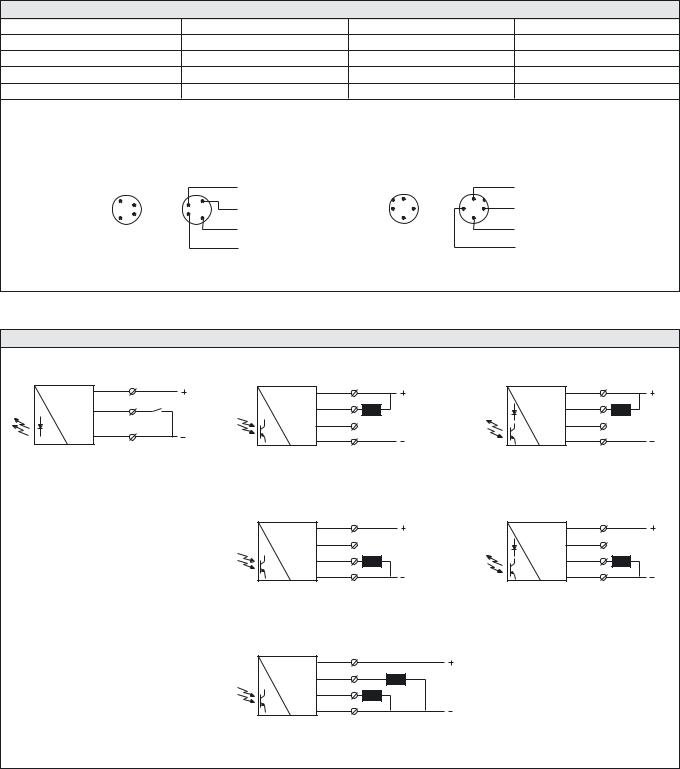
SPACEMASTER™ SERIES |
SM 7000 |
Connections |
|
|
|
|
|
|
|
|
|
|
|
|
|
|
|
|
|
Cable |
|
|
M8 Plug/Cable |
|
|
M12 Plug/Cable |
|
||
Supply + |
|
|
|
Brown |
|
|
Pin 1/Brown |
|
|
Pin 1/Brown |
|
||
Supply – |
|
|
|
Blue |
|
|
Pin 3/Blue |
|
|
Pin 3/Blue |
|
||
Control/output |
|
|
|
Black |
|
|
Pin 4/Black |
|
|
Pin 4/Black |
|
||
Output |
|
|
|
White |
|
|
Pin 2/White |
|
|
Pin 2/White |
|
||
|
|
4 pin, M8 |
|
|
|
4 pin, M12 |
|
|
|
|
|
||
Sensor Plug |
Cable Plug |
|
|
Sensor Plug |
Cable Plug |
|
|
|
|||||
(Male) |
|
(Female) |
|
|
(Male) |
(Female) |
|
|
|
||||
|
|
|
|
White |
|
|
|
|
|
|
Brown |
|
|
|
1 |
|
1 |
|
|
|
1 |
|
|
1 |
|
|
|
|
2 |
|
2 |
Brown |
|
|
|
|
White |
|
|
||
|
|
|
2 |
4 |
|
4 |
2 |
|
|
||||
|
|
|
|
|
|
|
|
||||||
|
4 |
|
4 |
|
|
3 |
|
|
3 |
|
|
||
|
|
|
|
|
|
|
|
|
|
||||
|
3 |
|
3 |
|
|
|
|
|
|
|
|
|
|
|
|
|
|
Blue |
|
|
|
|
|
|
Blue |
|
|
|
|
|
|
Black |
|
|
|
|
|
|
Black |
|
|
Wiring Diagrams |
|
|
|
|
|
|
|
|
|
|
|
|
|
Brown |
1 |
|
|
Brown |
1 |
|
|
|
|
|
Brown |
1 |
|
Black |
4 |
ON/OFF Switch |
White |
2 |
|
|
|
|
|
White |
2 |
|
|
|
|
|
|
Black |
4 |
Load |
|
|
|
|
Black |
4 |
Load |
|
|
|
|
|
|
|
|
|
|
||||
Blue |
3 |
|
|
|
NC* |
|
|
|
|
|
|
NC* |
|
|
|
|
|
Blue |
3 |
|
|
|
|
|
Blue |
3 |
|
|
|
|
|
*Do not connect black wire |
|
|
|
|
|
*Do not connect black wire |
|
||
SMT 7000 |
|
|
|
SMR 76xx (load as NPN) |
|
|
|
|
|
|
SMP/SMPF/SMRR 7600 (load as NPN) |
||
|
|
|
|
Brown |
1 |
|
|
|
|
|
Brown |
1 |
|
|
|
|
|
White |
2 |
|
|
|
|
|
White |
2 |
|
|
|
|
|
|
NC* |
|
|
|
|
|
|
NC* |
|
|
|
|
|
Black |
4 |
Load |
|
|
|
|
Black |
4 |
Load |
|
|
|
|
Blue |
3 |
|
|
|
|
|
Blue |
3 |
|
|
|
|
|
|
|
|
|
|
|
|
|
||
|
|
|
|
*Do not connect white wire |
|
|
|
|
|
*Do not connect white wire |
|
||
|
|
|
|
SMR 76xx (load as PNP) |
|
|
|
|
|
|
SMP/SMPF/SMRR 7600 (load as PNP) |
||
|
|
|
|
Brown |
1 |
|
|
|
|
|
|
|
|
|
|
|
|
White |
2 |
|
|
PNP load, light operated |
|
|
|||
|
|
|
|
Black |
4 |
Loads |
on white wire |
|
|
|
|||
|
|
|
|
PNP load, dark operated |
|
|
|||||||
|
|
|
|
|
|
|
|
|
|
||||
|
|
|
|
Blue |
3 |
|
|
on black wire |
|
|
|
||
|
|
|
|
|
|
|
|
|
|
|
|
|
|
|
|
|
|
SMR 77xx |
|
|
|
|
|
|
|
|
|
SELF-CONTAINED PHOTOELECTRIC SYSTEMS I 81
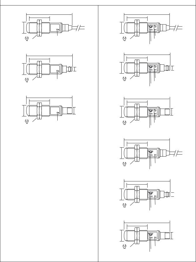
SM 7000 |
SPACEMASTER™ SERIES |
|
|
|
|
Dimensions and Descriptions |
|
|
|
|
|
Transmitter Models |
|
Receiver Models |
|
77 |
|
|
34 |
|
M18 x 1 |
|
M18 x 1 |
24 |
Power on indicator |
|
|
|
|
|
SMT 7000 TP/TS 5 |
|
|
78 |
|
|
34 |
|
M18 x 1 |
M8 x 1 |
M18 x 1 |
|
||
24 |
Power on indicator |
|
|
SMT 7000 TP/TS T4 |
|
|
77 |
|
|
34 |
|
M18 x 1 |
M12 x 1 |
M18 x 1 |
|
|
|
24 |
Power on indicator |
|
SMT 7000 TP/TS J
M18 x 1
M18 x 1
M18 x 1
(Units in mm)
|
77 |
|
|
34 |
|
|
Output indicator |
|
24 |
Light/dark switch |
|
Power on indicator |
||
|
||
|
Sensitivity adjustment |
|
SMR/SMP/SMPF/SMRR 76xx TP/TS 5 |
||
|
78 |
|
|
34 |
|
|
M8 x 1 |
|
24 |
Output indicator |
|
Light/dark switch |
||
|
||
|
Power on indicator |
|
|
Sensitivity adjustment |
|
SMR/SMP/SMPF/SMRR 76xx TP/TS T4 |
||
|
77 |
|
|
34 |
|
|
M12 x 1 |
|
|
Output indicator |
|
24 |
Light/dark switch |
|
Power on indicator |
||
|
||
|
Sensitivity adjustment |
|
SMR/SMP/SMPF/SMRR 76xx TP/TS J |
||
|
77 |
|
|
34 |
|
24
Signal indicator
Power on indicator
Sensitivity adjustment
SMR 77xx TP/TS 5
78
34
 M8 x 1
24 |
Signal indicator |
|
Power on indicator |
||
|
||
|
Sensitivity adjustment |
|
|
SMR 77xx TP/TS T4 |
|
|
77 |
|
|
34 |
M12 x 1
24
Signal indicator
Power on indicator
Sensitivity adjustment
SMR 77xx TP/TS J
(Units in mm)
82 I SELF-CONTAINED PHOTOELECTRIC SYSTEMS
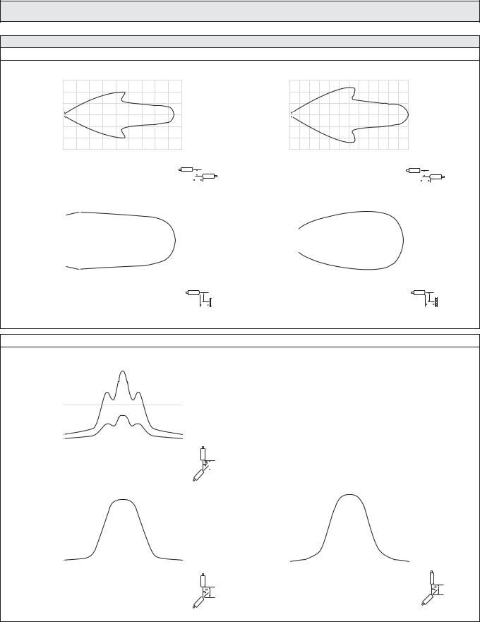
SPACEMASTER™ SERIES
Sensing Characteristics
Parallel Displacement
|
0,6 |
(m) |
0,4 |
|
|
Displacement |
0,2 |
|
0 |
|
– 0,2 |
|
– 0,4 |
|
– 0,6 |
|
0 |
1 |
2 |
3 |
|
4 |
5 |
6 |
|
7 |
8 |
9 |
|
|
|
|||
|
|
|
|
|
|
Range (m) |
|
|
|
|
|
|
|
|
|
|||
|
|
|
|
SMT 7000 and SMR 7x07 |
|
|
|
|
|
Y |
||||||||
|
|
|
|
|
|
|
|
|
||||||||||
|
|
|
|
|
|
|
|
|
|
|||||||||
|
0,15 |
|
|
|
|
|
|
X |
||||||||||
|
|
|
|
|
|
|
|
|
|
|
|
|
|
|
|
|
|
|
(m) |
0,10 |
|
|
|
|
|
|
|
|
|
|
|
|
|
|
|
|
|
|
|
|
|
|
|
|
|
|
|
|
|
|
|
|
|
|
||
0,05 |
|
|
|
|
|
|
|
|
|
|
|
|
|
|
|
|
|
|
Displacement |
|
|
|
|
|
|
|
|
|
|
|
|
|
|
|
|
|
|
|
|
|
|
|
|
|
|
|
|
|
|
|
|
|
|
|
||
–0,10 |
|
|
|
|
|
|
|
|
|
|
|
|
|
|
|
|
|
|
|
0,00 |
|
|
|
|
|
|
|
|
|
|
|
|
|
|
|
|
|
|
–0,05 |
|
|
|
|
|
|
|
|
|
|
|
|
|
|
|
|
|
|
–0,15 |
|
|
|
|
|
|
|
|
|
|
|
|
|
|
|
|
|
|
|
|
|
|
|
|
|
|
|
|
|
|
|
|
|
|
|
|
|
|
0,1 |
0,2 |
|
0,3 |
0,4 |
|
0,5 |
0,6 |
|
|
|||||||
|
0 |
|
|
|
|
|
||||||||||||
Range (m)
Y
SMP 7x00 with 20cm x 20cm white paper |
X |
Angular Displacement
|
24 |
|
|
|
|
|
|
|
|
|
|
|
|
|
|
|
|
|
|
|
|
|
|
|
|
|
|
|
|
|
|
|
|
|
|
|
|
|
|
|
|
(m) |
20 |
|
|
|
|
|
|
|
|
|
|
|
|
|
|
|
|
|
|
|
|
|
|
|
|
|
|
|
|
|
|
|
|
|
|
|
|
|
|
||
16 |
|
|
|
|
|
|
|
|
|
|
|
|
|
|
|
|
|
|
|
|
Range |
|
|
|
|
|
|
|
|
|
|
|
|
|
|
|
|
|
|
|
|
8 |
|
|
|
|
|
|
|
|
|
|
|
|
|
|
|
|
|
|
|
|
|
12 |
|
|
|
|
|
|
SMR |
7x20 |
|
|
|
|
|
|
|
|
|
|
|
|
4 |
|
|
|
|
|
|
|
|
|
|
|
|
|
|
|
|
|
|
|
|
|
|
|
|
|
|
SMR |
7x07 |
|
|
|
|
|
|
|
|
|
|
||
|
|
|
|
|
|
|
|
|
|
|
|
|
|
|
|
|
|
|||
|
0 |
|
|
|
|
|
|
|
|
|
|
|
|
|
|
|
|
|
|
|
|
|
|
|
|
|
|
|
|
|
|
|
|
|
|
|
|
|
|
|
|
|
–20 |
–15 |
–10 |
–5 |
0 |
5 |
10 |
15 |
20 |
|
|
|||||||||
|
|
|
|
|
|
|
|
Degrees |
|
|
|
|
|
|
|
|
|
|
||
|
|
|
|
|
|
|
|
SMT 7000 |
|
|
|
|
|
|
|
Y |
||||
|
|
|
|
|
|
|
|
|
|
|
|
|
|
|
||||||
|
9 |
|
|
|
|
|
|
|
|
|
|
|
|
|
|
|||||
|
|
|
|
|
|
|
|
|
|
|
|
|
|
|
||||||
|
|
|
|
|
|
|
|
|
|
|
|
|
|
|
|
|
|
|
|
|
|
8 |
|
|
|
|
|
|
|
|
|
|
|
|
|
|
|
|
|
|
|
|
|
|
|
|
|
|
|
|
|
|
|
|
|
|
|
|
|
|
|
|
|
7 |
|
|
|
|
|
|
|
|
|
|
|
|
|
|
|
|
|
|
|
|
|
|
|
|
|
|
|
|
|
|
|
|
|
|
|
|
|
|
|
|
(m) |
6 |
|
|
|
|
|
|
|
|
|
|
|
|
|
|
|
|
|
|
|
|
|
|
|
|
|
|
|
|
|
|
|
|
|
|
|
|
|
|
||
5 |
|
|
|
|
|
|
|
|
|
|
|
|
|
|
|
|
|
|
|
|
Range |
|
|
|
|
|
|
|
|
|
|
|
|
|
|
|
|
|
|
|
|
|
|
|
|
|
|
|
|
|
|
|
|
|
|
|
|
|
|
|
||
3 |
|
|
|
|
|
|
|
|
|
|
|
|
|
|
|
|
|
|
|
|
|
4 |
|
|
|
|
|
|
|
|
|
|
|
|
|
|
|
|
|
|
|
|
2 |
|
|
|
|
|
|
|
|
|
|
|
|
|
|
|
|
|
|
|
|
|
|
|
|
|
|
|
|
|
|
|
|
|
|
|
|
|
|
|
|
|
1 |
|
|
|
|
|
|
|
|
|
|
|
|
|
|
|
|
|
|
|
|
|
|
|
|
|
|
|
|
|
|
|
|
|
|
|
|
|
|
|
|
|
0 |
|
|
|
|
|
|
|
|
|
|
|
|
|
|
|
|
|
|
|
|
|
|
|
|
|
|
|
|
|
|
|
|
|
|
|
|
|
|
|
|
|
–20 |
–15 |
–10 |
–5 |
0 |
5 |
10 |
15 |
20 |
|
|
|||||||||
Degrees
Y
SMR 7x07
Telco reserves the right to change specifications without notice.
SM 7000
|
1,5 |
(m) |
1,0 |
|
|
Displacement |
0,5 |
|
|
|
0 |
|
– 0,5 |
|
–1,0 |
|
– 1,5 |
|
0 |
2 |
4 |
6 |
8 |
10 |
12 |
14 |
16 |
18 |
20 |
22 |
24 |
|
|
||||
|
|
|
|
|
|
|
Range (m) |
|
|
|
|
|
|
|
|
|
|||
|
|
|
|
|
SMT 7000 and SMR 7x20 |
|
|
|
|
|
Y |
||||||||
|
|
|
|
|
|
|
|
|
|
||||||||||
|
|
|
|
|
|
|
|
|
|
|
|||||||||
|
0,15 |
|
|
|
|
|
|
|
X |
||||||||||
|
|
|
|
|
|
|
|
|
|
|
|
|
|
|
|
|
|
|
|
(m) |
0,10 |
|
|
|
|
|
|
|
|
|
|
|
|
|
|
|
|
|
|
|
|
|
|
|
|
|
|
|
|
|
|
|
|
|
|
|
|
||
0,05 |
|
|
|
|
|
|
|
|
|
|
|
|
|
|
|
|
|
|
|
Displacement |
|
|
|
|
|
|
|
|
|
|
|
|
|
|
|
|
|
|
|
|
|
|
|
|
|
|
|
|
|
|
|
|
|
|
|
|
|
||
0,00 |
|
|
|
|
|
|
|
|
|
|
|
|
|
|
|
|
|
|
|
|
|
|
|
|
|
|
|
|
|
|
|
|
|
|
|
|
|
|
|
|
–0,05 |
|
|
|
|
|
|
|
|
|
|
|
|
|
|
|
|
|
|
|
|
|
|
|
|
|
|
|
|
|
|
|
|
|
|
|
|
|
|
|
–0,10 |
|
|
|
|
|
|
|
|
|
|
|
|
|
|
|
|
|
|
|
|
|
|
|
|
|
|
|
|
|
|
|
|
|
|
|
|
|
|
|
–0,15 |
|
|
|
|
|
|
|
|
|
|
|
|
|
|
|
|
|
|
|
|
|
|
|
|
|
|
|
|
|
|
|
|
|
|
|
|
|
|
0 |
0,5 |
1,0 |
1,5 |
2,0 |
2,5 |
3,0 |
3,5 |
|
|
|
Range (m) |
|
|
|
|
Y
SMRR 7x00 with Ø84mm reflector |
X |
|
24 |
|
|
|
|
|
|
|
|
|
|
|
|
|
|
|
|
|
|
|
|
|
|
(m) |
20 |
|
|
|
|
|
|
|
|
|
|
|
|
|
|
|
|
|
|
|
|
||
16 |
|
|
|
|
|
|
|
|
|
|
|
Range |
|
|
|
|
|
|
|
|
|
|
|
8 |
|
|
|
|
|
|
|
|
|
|
|
|
12 |
|
|
|
|
|
|
|
|
|
|
|
4 |
|
|
|
|
|
|
|
|
|
|
|
|
|
|
|
|
|
|
|
|
|
|
|
0 |
|
|
|
|
|
|
|
|
|
|
|
|
|
|
|
|
|
|
|
|
|
|
|
–20 –15 –10 –5 |
0 |
5 |
10 15 20 |
|||||||
Degrees
Y
SMR 7x20
SELF-CONTAINED PHOTOELECTRIC SYSTEMS I 83
SPACEMASTER™ SERIES |
SM 8000 |
Description
Operation mode and max sensing range:
Thru beam: 0-20 m Diffuse proximity: 0-0,5 m Retro reflective: 0-3 m
Fibre: Dependent on fibre optic
Cable or plug connection
Sensitivity adjustment via potentiometer
Switch selectable light or dark function
Power and output indicators
High tolerance to hostile environments
10-30 V dc or 20-250 V ac supply voltage
3 wire, NPN or PNP transistor output or 2 wire, SCR output
Test input
The 8000 series consists of a self-contained transmitter SMT, and a receiver SMR which are to be used in thru beam mode, an SMP for diffuse proximity, SMRR for retro reflective and an SMPF for use with fibre optic cables. All are offered with sensitivity adjustment via integral potentiometer with either cable or plug connection.
The complete series is available either as 3 wire, NPN or PNP transistor output with a 10-30 V dc supply voltage, or as 2 wire, SCR output with a
20-250 V ac supply voltage both offering switch selectable light or dark function. The control input in the 10-30 V dc SMT is intended to be used for disabling or enabling the transmitting power temporarily for test purpose or for multiplexing applications.
The dc series is protected against reverse polarity of power supplies, control input and output signals. The output is protected against short circuit and inductive loads.
Technical Data
|
|
SMT |
|
SMR |
|
SMP/SMPF |
|
SMRR |
|
|
|
|
|
|
|
|
|||
|
|
|
8x20 |
|
8x00 |
|
|
|
|
|
|
|
|
|
|
|
|
|
|
Supply voltage |
ac |
20 – 250 V ac |
– |
|
|
|
20 – 250 V ac |
|
|
|
|
|
|
|
|
|
|
|
|
|
dc |
|
|
|
10 – 30 V dc |
|
|
||
|
|
|
|
|
|
|
|
|
|
Voltage ripple |
|
|
|
15 % |
|
|
|
|
|
|
|
|
|
|
|
|
|
|
|
Reverse polarity protected |
dc |
|
|
|
Yes |
|
|
|
|
|
|
|
|
|
|
|
|
|
|
Short circuit protected |
dc |
– |
|
|
|
Yes |
|
|
|
|
|
|
|
|
|
|
|
|
|
Current consumption |
ac |
3 mA |
– |
|
|
|
2 mA |
|
|
dc |
|
|
|
|
|
|
|
|
|
|
15 mA |
|
5 mA |
|
|
14 mA |
|||
|
|
|
|
|
|
|
|
|
|
Maximum output load |
ac |
– |
– |
|
|
|
200 mA |
|
|
|
|
|
|
|
|
|
|
||
dc |
|
|
|
120 mA @ 30 V dc |
|
|
|||
|
|
|
|
|
|
|
|||
|
|
|
|
|
|
|
|
|
|
Maximum residual voltage |
ac |
– |
– |
|
|
|
8 V |
|
|
dc |
|
|
|
|
|
|
|
||
|
|
|
1,5 V |
|
|
||||
|
|
|
|
|
|
|
|||
|
|
|
|
|
|
|
|
|
|
Max. operation frequency |
ac |
– |
– |
|
|
|
20 Hz |
|
|
|
|
|
|
|
|
|
|
||
dc |
100 Hz |
|
|
|
250 Hz |
|
|
||
|
|
|
|
|
|
|
|||
|
|
|
|
|
|
|
|
|
|
Response time tON / tOFF |
ac |
– |
– |
|
|
|
25 ms / 25 ms |
|
|
|
|
|
|
|
|
|
|
||
dc |
5 ms / 5 ms |
|
|
|
2 ms / 2 ms |
|
|
||
|
|
|
|
|
|
|
|||
|
|
|
|
|
|
|
|
|
|
Power on indicator |
|
|
|
|
Green LED |
|
|
|
|
|
|
|
|
|
|
|
|
|
|
Output indicator |
|
– |
|
|
|
Yellow LED |
|
|
|
|
|
|
|
|
|
|
|
||
Hysteresis |
|
– |
Approx. 10 – 30 % |
|
Approx. 5 – 15 % |
||||
|
|
|
|
|
|
|
|
|
|
Transmitter diode |
|
Ga Al As (880 nm) |
|
– |
|
Ga Al As (880 nm) |
|||
|
|
|
|
|
|
|
|
|
|
Opening angle |
|
– |
|
+/– 6° |
|
+/– 4° |
|
+/– 1,5° |
|
|
|
|
|
|
|
|
|
|
|
Emission angle |
|
+/– 2° |
|
|
|
– |
|
|
|
|
|
|
|
|
|
|
|
|
|
SELF-CONTAINED PHOTOELECTRIC SYSTEMS I 85

SM 8000 |
|
|
|
|
|
|
|
|
|
|
SPACEMASTER™ SERIES |
|||||||
|
|
|
|
|
|
|
|
|
|
|
|
|
|
|
|
|
|
|
Environmental Data |
|
|
|
|
|
|
|
|
|
|
|
|
|
|
|
|||
|
|
|
|
|
|
|
SMT |
|
|
SMR |
|
SMP |
|
SMRR/SMPF |
||||
|
|
|
|
|
|
|
|
|
|
|
|
|
|
|||||
|
|
|
|
|
|
|
|
|
8x20 |
|
|
8x00 |
|
|
|
|
|
|
|
|
|
|
|
|
|
|
|
|
|
|
|
|
|
|
|
||
Vibration |
|
|
|
|
|
|
|
|
|
10 – 55 Hz, 0,5 mm |
|
|
|
|
||||
|
|
|
|
|
|
|
|
|
|
|
|
|
|
|
|
|
|
|
Shock |
|
|
|
|
|
|
|
|
|
30 g |
|
|
|
|
|
|||
|
|
|
|
|
|
|
|
|
|
|
|
|
|
|
||||
Light immunity, @ 5° incidence |
|
|
– |
|
> 7000 lux |
|
|
|
|
> 10 000 lux |
|
|
||||||
|
|
|
|
|
|
|
|
|
|
|
|
|
|
|
|
|||
Temperature, operation |
|
|
|
|
|
|
|
|
– 20 to +60 ºC |
|
|
|
|
|||||
|
|
|
|
|
|
|
|
|
|
|
|
|
|
|
|
|||
Temperature, storage |
|
|
|
|
|
|
|
|
– 40 to +80 ºC |
|
|
|
|
|||||
|
|
|
|
|
|
|
|
|
|
|
|
|
|
|
|
|
|
|
Sealing class |
|
ac |
|
|
|
|
|
|
|
IP 60 |
|
|
|
|
|
|||
|
|
|
|
|
|
|
|
|
|
|
|
|
|
|
|
|||
|
dc |
|
|
|
|
|
|
|
IP 67 |
|
|
|
|
|
||||
|
|
|
|
|
|
|
|
|
|
|
|
|
|
|
|
|||
|
|
|
|
|
|
|
|
|
|
|
|
|
|
|
|
|
|
|
Approvals |
|
ac |
|
|
|
|
|
|
|
a |
|
|
|
|
|
|||
|
dc |
|
|
|
|
|
|
|
|
|
|
|
|
|
|
|||
|
|
|
|
|
|
|
|
a |
|
|
|
|
|
|||||
|
|
|
|
|
|
|
|
|
|
|
|
|
|
|
|
|||
|
|
|
|
|
|
|
|
|
|
|
|
|
|
|
|
|
|
|
|
|
|
|
|
|
|
|
|
|
|
|
|
|
|
|
|
|
|
Available Types |
|
|
|
|
|
|
|
|
|
|
|
|
|
|
|
|||
|
Type |
|
Power |
Control |
Output |
Connection |
|
|
5 m Cable |
3 pin, M8 Plug |
4 pin, M12 Plug |
Range |
||||||
Transmitter |
|
|
Supply |
Feature |
|
|
Housing Material |
Housing Type |
|
|
|
|
Order Reference |
|
|
|
|
|
|
|
|
|
|
|
|
|
|
|
|
|
|
|
|
|
|
|
|
8000 |
|
10 – 30 |
Test |
|
|
Polycarbonate |
|
|
|
|
SMT 8000 PG 5 |
SMT 8000 PG T3 |
SMT 8000 PG J |
20 m |
||||
|
|
|
|
|
|
|
|
|||||||||||
|
|
V dc |
Input |
– |
Stainless Steel |
|
M18 x 1 |
|
|
SMT 8000 MG 5 |
SMT 8000 MG T3 |
SMT 8000 MG J |
||||||
|
|
|
|
|
|
|
|
|||||||||||
|
|
|
|
|
|
|
|
|
|
|
|
|
|
|
|
|||
|
8600 |
|
20 – 250 |
– |
|
|
Polycarbonate |
|
|
|
|
SMT 8600 PG 5 |
– |
|
– |
7 m |
||
|
|
V ac |
|
|
Stainless Steel |
|
|
|
|
SMT 8600 MG 5 |
– |
|
– |
|||||
|
|
|
|
|
|
|
|
|
|
|
|
|
||||||
|
|
|
|
|
|
|
|
|
|
|
|
|
|
|
|
|
|
|
|
|
|
|
|
|
|
|
|
|
|
|
|
|
|
|
|
|
|
|
8400 |
|
|
|
NPN |
Polycarbonate |
|
|
|
|
SMR 8400 PG 5 |
SMR 8400 PG T3 |
SMR 8400 PG J |
|
|
|||
|
|
|
|
|
|
|
|
|
|
|
|
|
|
|
|
|||
|
|
|
|
Stainless Steel |
|
|
|
|
SMR 8400 MG 5 |
SMR 8400 MG T3 |
SMR 8400 MG J |
0-7 m |
||||||
|
|
|
|
|
|
|
|
|
|
|
||||||||
|
|
|
|
|
|
|
|
|
|
|
|
|
|
|
|
|
||
|
8500 |
|
|
Sensitivity |
|
|
Polycarbonate |
|
|
|
|
SMR 8500 PG 5 |
SMR 8500 PG T3 |
SMR 8500 PG J |
||||
|
|
|
|
|
|
|
|
|
|
|
||||||||
|
|
|
|
|
|
|
|
|
|
|
|
|
|
|
|
|
||
|
|
|
|
|
Stainless Steel |
|
|
|
|
SMR 8500 MG 5 |
SMR 8500 MG T3 |
SMR 8500 MG J |
|
|
||||
Receiver |
|
|
10 – 30 |
pot. and |
PNP |
|
|
|
|
|
|
|||||||
|
|
V dc |
light/dark |
|
|
|
|
|
|
|
|
|
|
0-20 m |
||||
|
8520 |
|
Polycarbonate |
|
|
|
|
SMR 8520 PG 5 |
SMR 8520 PG T3 |
SMR 8520 PG J |
|
|
||||||
|
|
|
|
|
|
|
|
|
|
|||||||||
|
|
|
switch |
|
|
|
M18 x 1 |
|
|
|
|
|||||||
|
|
|
|
|
|
|
|
|
|
|
|
|
|
|
|
|||
|
|
|
|
|
Stainless Steel |
|
|
SMR 8520 MG 5 |
SMR 8520 MG T3 |
SMR 8520 MG J |
|
|
||||||
|
|
|
|
|
|
|
|
|
|
|
|
|
||||||
|
|
|
|
|
|
|
|
|
|
|
|
|
|
|
|
|
|
|
|
8420 |
|
|
|
NPN |
Polycarbonate |
|
|
|
|
SMR 8420 PG 5 |
SMR 8420 PG T3 |
SMR 8420 PG J |
|
|
|||
|
|
|
|
|
|
|
|
|
|
|
|
|
|
|
|
|||
|
|
|
|
Stainless Steel |
|
|
|
|
SMR 8420 MG 5 |
SMR 8420 MG T3 |
SMR 8420 MG J |
|
|
|||||
|
|
|
|
|
|
|
|
|
|
|
|
|
||||||
|
|
|
|
|
|
|
|
|
|
|
|
|
|
|
|
|
|
|
|
8800 |
|
20 – 250 |
Light/dark |
SCR |
Polycarbonate |
|
|
|
|
SMR 8800 PG 5 |
– |
|
– |
7 m |
|||
|
|
V ac |
switch |
Stainless Steel |
|
|
|
|
SMR 8800 MG 5 |
– |
|
– |
||||||
|
|
|
|
|
|
|
|
|
|
|
|
|||||||
|
|
|
|
|
|
|
|
|
|
|
|
|
|
|
|
|
|
|
|
|
|
|
|
|
|
|
|
|
|
|
|
|
|
|
|
|
|
|
8500 |
|
|
|
PNP |
Polycarbonate |
|
|
|
|
SMP 8500 PG 5 |
SMP 8500 PG T3 |
SMP 8500 PG J |
|
|
|||
|
|
|
|
|
|
|
|
|
|
|
|
|
|
|
|
|||
Proximity |
|
|
10 – 30 |
switch |
|
|
Stainless Steel |
|
|
|
|
SMP 8500 MG 5 |
SMP 8500 MG T3 |
SMP 8500 MG J |
|
|
||
|
|
|
V dc |
Sensitivity |
|
|
|
|
|
|
|
|
|
|
|
|
|
|
|
8400 |
|
pot. and |
|
|
Polycarbonate |
|
|
|
|
SMP 8400 PG 5 |
SMP 8400 PG T3 |
SMP 8400 PG J |
|
|
|||
|
|
|
NPN |
|
M18 x 1 |
|
|
0-0,5 m |
||||||||||
|
|
|
light/dark |
|
|
|
|
|
|
|
|
|
||||||
|
|
|
|
|
|
Stainless Steel |
|
|
|
|
SMP 8400 MG 5 |
SMP 8400 MG T3 |
SMP 8400 MG J |
|
|
|||
|
|
|
|
|
|
|
|
|
|
|
|
|
||||||
|
|
|
|
|
|
|
|
|
|
|
|
|
|
|
|
|
|
|
|
8800 |
|
20 – 250 |
|
SCR |
Polycarbonate |
|
|
|
|
SMP 8800 PG 5 |
– |
|
– |
|
|
||
|
|
V ac |
|
Stainless Steel |
|
|
|
|
SMP 8800 MG 5 |
– |
|
– |
|
|
||||
|
|
|
|
|
|
|
|
|
|
|
|
|
||||||
|
|
|
|
|
|
|
|
|
|
|
|
|
|
|
|
|
|
|
|
|
|
|
|
|
|
|
|
|
|
|
|
|
|
|
|
|
|
|
8500 |
|
|
|
PNP |
Polycarbonate |
|
|
|
|
SMPF 8500 PG 5 |
SMPF 8500 PG T3 |
SMPF 8500 PG J |
|
|
|||
Sensor |
|
|
|
|
|
|
|
|
|
|
|
|
|
|
|
|||
|
10 – 30 |
Sensitivity |
Stainless Steel |
|
M18 x 1 |
|
|
SMPF 8500 MG 5 |
SMPF 8500 MG T3 |
SMPF 8500 MG J |
|
|
||||||
8400 |
|
NPN |
|
|
|
|
|
|||||||||||
|
|
|
|
|
|
|
|
|
|
|
||||||||
|
|
|
|
|
|
|
|
|
|
|
|
|
|
|
|
|
||
|
|
|
V dc |
pot. and |
|
|
Polycarbonate |
|
|
|
|
SMPF 8400 PG 5 |
SMPF 8400 PG T3 |
SMPF 8400 PG J |
Refer to |
|||
|
|
|
|
light/dark |
|
|
|
|
|
|
|
|
|
|
|
|
page 130 |
|
Fibre |
|
|
|
|
|
Stainless Steel |
|
|
|
|
SMPF 8400 MG 5 |
SMPF 8400 MG T3 |
SMPF 8400 MG J |
|||||
|
|
20 – 250 |
switch |
|
|
|
|
|
|
|
|
|||||||
|
|
|
|
Polycarbonate |
|
|
|
|
SMPF 8800 PG 5 |
– |
|
– |
|
|
||||
|
8800 |
|
V ac |
SCR |
|
|
|
|
|
|
|
|
|
|
|
|
||
|
|
|
|
|
|
|
|
|
|
|
|
|
|
|
||||
|
|
|
Stainless Steel |
|
|
|
|
SMPF 8800 MG 5 |
– |
|
– |
|
|
|||||
|
|
|
|
|
|
|
|
|
|
|
|
|
||||||
|
|
|
|
|
|
|
|
|
|
|
|
|
|
|
|
|
|
|
Note: Fibre optic cable to be ordered separately. |
|
|
|
|
|
|
|
|
|
|
|
|||||||
|
|
|
|
|
|
|
|
|
|
|
|
|
|
|
|
|
|
|
Reflective |
8500 |
|
|
|
PNP |
Polycarbonate |
|
|
|
|
SMRR 8500 PG 5 |
SMRR 8500 PG T3 |
SMRR 8500 PG J |
|
|
|||
|
|
|
|
|
|
|
|
|
|
|
|
|
|
|
||||
|
10 – 30 |
light/dark |
Stainless Steel |
|
|
|
|
SMRR 8500 MG 5 |
SMRR 8500 MG T3 |
SMRR 8500 MG J |
0-3 m |
|||||||
8400 |
|
NPN |
|
|
|
|
||||||||||||
|
|
|
V dc |
Sensitivity |
|
|
|
|
|
|
|
|
|
|
|
|
|
|
|
|
|
|
pot. and |
|
|
Polycarbonate |
|
M18 x 1 |
|
|
SMRR 8400 PG 5 |
SMRR 8400 PG T3 |
SMRR 8400 PG J |
|
|
||
Retro |
8800 |
|
|
switch |
SCR |
Stainless Steel |
|
|
|
SMRR 8400 MG 5 |
SMRR 8400 MG T3 |
SMRR 8400 MG J |
|
|
||||
|
|
|
|
|
|
|
|
|||||||||||
|
|
|
|
|
|
|
|
|
|
|
|
|
|
|||||
|
|
|
20 – 250 |
|
|
Polycarbonate |
|
|
|
|
SMRR 8800 PG 5 |
– |
|
– |
|
|
||
|
|
|
|
|
|
|
|
|
|
|
|
|
||||||
|
|
|
V ac |
|
|
|
Stainless Steel |
|
|
|
|
SMRR 8800 MG 5 |
– |
|
– |
|
|
|
|
|
|
|
|
|
|
|
|
|
|
|
|
|
|
|
|
|
|
Note: Reflector to be ordered separately.
86 I SELF-CONTAINED PHOTOELECTRIC SYSTEMS
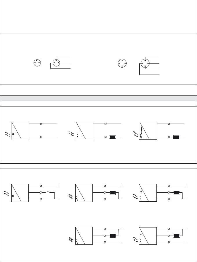
SPACEMASTER™ SERIES |
|
|
SM 8000 |
|
|
|
|
|
|
|
|
Connections |
|
|
|
|
|
|
|
Cable |
M8 Plug/Cable |
M12 Plug/Cable |
|
|
|
|
|
|
|
AC supply |
|
Blue & Brown |
– |
– |
|
|
|
|
|
|
|
Supply + |
|
Brown |
Pin 1/Brown |
Pin 1/Brown |
|
|
|
|
|
|
|
Supply – |
|
Blue |
Pin 3/Blue |
Pin 3/Blue |
|
|
|
|
|
|
|
SMT control |
|
Black |
Pin 4/Black |
Pin 4/Black |
|
|
|
|
|
|
|
SMR output |
|
Black |
Pin 4/Black |
Pin 4/Black |
|
|
|
|
|
|
|
3 pin, M8 |
4 pin, M12 |
||
Sensor Plug |
Cable Plug |
Sensor Plug |
Cable Plug |
(Male) |
(Female) |
(Male) |
(Female) |
|
|
|
|
Black |
|
|
|
|
|
Brown |
|
4 |
|
|
4 |
Brown |
|
|
1 |
|
1 |
White |
|
|
|
|
2 |
4 |
4 |
2 |
|
||||
1 |
3 |
3 |
1 |
|
|
||||||
|
|
|
|
|
|
|
3 |
|
3 |
|
|
|
|
|
|
Blue |
|
|
|
|
|
Blue |
|
|
|
|
|
|
|
|
|
|
|
Black |
|
Wiring Diagrams |
|
|
|
|
|
|
|
|
|
|
|
AC Models |
|
|
|
|
|
|
|
|
|
|
|
Brown |
|
|
|
|
Brown |
|
|
|
|
Brown |
|
Blue |
|
|
|
|
Blue |
Load |
|
|
|
Blue |
Load |
|
|
|
|
|
|
|
|
|
|||
SMT 8600 |
|
|
|
SMR 8800 |
|
|
|
SMP / SMPF / SMRR 8800 |
|
||
DC Models |
|
|
|
|
|
|
|
|
Brown |
1 |
|
Brown |
1 |
|
Brown |
1 |
|
Black |
4 |
ON/OFF Switch |
Black |
4 |
Load |
Black |
4 |
Load |
Blue |
3 |
|
Blue |
3 |
|
Blue |
3 |
|
SMT 8000 |
|
|
SMR 85xx |
|
|
SMP / SMPF / SMRR 8500 |
|
|
|
|
|
Brown |
1 |
|
Brown |
1 |
|
|
|
|
Black |
4 |
Load |
Black |
4 |
Load |
|
|
|
|
|
||||
|
|
|
Blue |
3 |
|
Blue |
3 |
|
|
|
|
SMR 84xx |
|
|
SMP / SMPF / SMRR 8400 |
|
|
SELF-CONTAINED PHOTOELECTRIC SYSTEMS I 87

SM 8000 |
SPACEMASTER™ SERIES |
|
|
|
|
Dimensions and Descriptions |
|
|
|
|
|
AC Models
75
45
M18 x 1
24 |
Power on indicator |
SMT PG/MG 5
75
45
M18 x 1
|
Output indicator |
|
24 |
Light/dark switch |
|
Power on indicator |
||
|
SMR PG/MG 5
75
45
M18 x 1
|
Output indicator |
|
24 |
Light/dark switch |
|
Power on indicator |
||
|
||
|
Sensitivity adjustment |
SMP/SMPF/SMRR PG/MG 5
DC Models
M18 x 1
M18 x 1
M18 x 1
M18 x 1
M18 x 1
M18 x 1
(Units in mm)
77
34
24 |
Power on indicator |
|
|
|
SMT PG/MG 5 |
|
78 |
|
34 |
 M8 x 1
 24 Power on indicator
SMT PG/MG T3
77
34
M12 x 1
24 |
Power on indicator |
SMT PG/MG J
77
34
|
Output indicator |
|
24 |
Light/dark switch |
|
Power on indicator |
||
|
||
|
Sensitivity adjustment |
SMR/SMP/SMPF/SMRR PG/MG 5
78
34
 M8 x 1
24
Output indicator
Light/dark switch
Power on indicator
Sensitivity adjustment
SMR/SMP/SMPF/SMRR PG/MG T3
77
34
M12 x 1
|
Output indicator |
|
24 |
Light/dark switch |
|
Power on indicator |
||
|
||
|
Sensitivity adjustment |
SMR/SMP/SMPF/SMRR PG/MG J
(Units in mm)
88 I SELF-CONTAINED PHOTOELECTRIC SYSTEMS
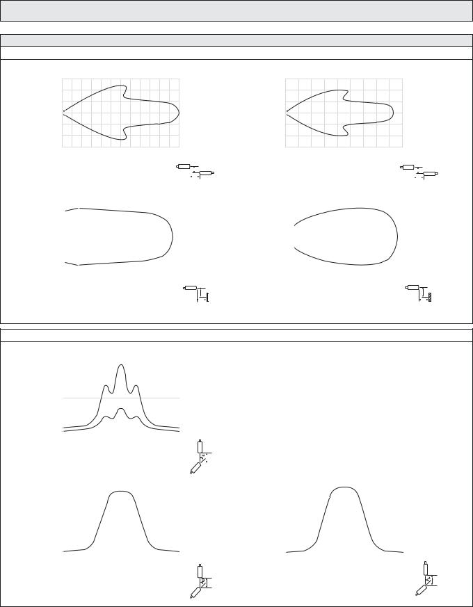
SPACEMASTER™ SERIES
Sensing Characteristics
Parallel Displacement
|
1,5 |
(m) |
1,0 |
|
|
Displacement |
0,5 |
|
|
|
0 |
|
– 0,5 |
|
–1,0 |
|
– 1,5 |
|
0 |
2 |
4 |
6 |
8 |
10 |
12 |
14 |
16 |
18 |
20 |
22 |
24 |
|
|
|
|
|
|
|
|
|
Range (m) |
|
|
|
|
|
|
|
|
||
|
|
|
|
SMT 8x00 and SMR 8x20 |
|
|
|
|
|
Y |
||||||
|
|
|
|
|
|
|
|
|
||||||||
|
|
|
|
|
|
|
|
|
|
|||||||
|
0,15 |
|
|
|
|
|
|
X |
||||||||
|
|
|
|
|
|
|
|
|
|
|
|
|
|
|
|
|
(m) |
0,10 |
|
|
|
|
|
|
|
|
|
|
|
|
|
|
|
|
|
|
|
|
|
|
|
|
|
|
|
|
|
|
||
0,05 |
|
|
|
|
|
|
|
|
|
|
|
|
|
|
|
|
Displacement |
|
|
|
|
|
|
|
|
|
|
|
|
|
|
|
|
|
|
|
|
|
|
|
|
|
|
|
|
|
|
|
||
–0,10 |
|
|
|
|
|
|
|
|
|
|
|
|
|
|
|
|
|
0,00 |
|
|
|
|
|
|
|
|
|
|
|
|
|
|
|
|
–0,05 |
|
|
|
|
|
|
|
|
|
|
|
|
|
|
|
|
–0,15 |
|
|
|
|
|
|
|
|
|
|
|
|
|
|
|
|
|
|
|
|
|
|
|
|
|
|
|
|
|
|
|
|
|
|
|
|
|
|
|
|
|
|
|
|
|
|
|
|
|
0 |
0,1 |
0,2 |
0,3 |
0,4 |
0,5 |
0,6 |
|
|
|
Range (m) |
|
|
|
Y
SMP 8x00 with 20cm x 20cm white paper |
X |
Angular Displacement
|
24 |
|
|
|
|
|
|
|
|
|
|
|
|
|
|
|
|
|
|
|
|
|
|
|
|
|
|
|
|
|
|
|
|
|
|
|
|
|
|
|
|
(m) |
20 |
|
|
|
|
|
|
|
|
|
|
|
|
|
|
|
|
|
|
|
|
|
|
|
|
|
|
|
|
|
|
|
|
|
|
|
|
|
|
||
16 |
|
|
|
|
|
|
|
|
|
|
|
|
|
|
|
|
|
|
|
|
Range |
|
|
|
|
|
|
SMR |
8x20 |
|
|
|
|
|
|
|
|
|
|
||
8 |
|
|
|
|
|
|
|
|
|
|
|
|
|
|
|
|
||||
|
12 |
|
|
|
|
|
|
|
|
|
|
|
|
|
|
|
|
|||
|
4 |
|
|
|
|
|
|
|
|
|
|
|
|
|
|
|
|
|
|
|
|
|
|
|
|
|
|
SMR |
8x00 |
|
|
|
|
|
|
|
|
|
|
||
|
|
|
|
|
|
|
|
|
|
|
|
|
|
|
|
|
|
|||
|
0 |
|
|
|
|
|
|
|
|
|
|
|
|
|
|
|
|
|
|
|
|
|
–15 |
–10 |
–5 |
0 |
5 |
10 |
15 |
20 |
|
|
|||||||||
|
–20 |
|
|
|||||||||||||||||
|
|
|
|
|
|
|
|
|
Degrees |
|
|
|
|
|
|
|
|
|
|
|
|
|
|
|
|
|
|
|
SMT 8000 |
|
|
|
|
|
|
|
Y |
||||
|
|
|
|
|
|
|
|
|
|
|
|
|
|
|
||||||
|
9 |
|
|
|
|
|
|
|
|
|
|
|
|
|
|
|||||
|
|
|
|
|
|
|
|
|
|
|
|
|
|
|
||||||
|
|
|
|
|
|
|
|
|
|
|
|
|
|
|
|
|
|
|
|
|
|
8 |
|
|
|
|
|
|
|
|
|
|
|
|
|
|
|
|
|
|
|
|
|
|
|
|
|
|
|
|
|
|
|
|
|
|
|
|
|
|
|
|
|
7 |
|
|
|
|
|
|
|
|
|
|
|
|
|
|
|
|
|
|
|
|
|
|
|
|
|
|
|
|
|
|
|
|
|
|
|
|
|
|
|
|
(m) |
6 |
|
|
|
|
|
|
|
|
|
|
|
|
|
|
|
|
|
|
|
|
|
|
|
|
|
|
|
|
|
|
|
|
|
|
|
|
|
|
||
5 |
|
|
|
|
|
|
|
|
|
|
|
|
|
|
|
|
|
|
|
|
Range |
|
|
|
|
|
|
|
|
|
|
|
|
|
|
|
|
|
|
|
|
|
|
|
|
|
|
|
|
|
|
|
|
|
|
|
|
|
|
|
||
3 |
|
|
|
|
|
|
|
|
|
|
|
|
|
|
|
|
|
|
|
|
|
4 |
|
|
|
|
|
|
|
|
|
|
|
|
|
|
|
|
|
|
|
|
2 |
|
|
|
|
|
|
|
|
|
|
|
|
|
|
|
|
|
|
|
|
|
|
|
|
|
|
|
|
|
|
|
|
|
|
|
|
|
|
|
|
|
1 |
|
|
|
|
|
|
|
|
|
|
|
|
|
|
|
|
|
|
|
|
|
|
|
|
|
|
|
|
|
|
|
|
|
|
|
|
|
|
|
|
|
0 |
|
|
|
|
|
|
|
|
|
|
|
|
|
|
|
|
|
|
|
|
|
|
|
|
|
|
|
|
|
|
|
|
|
|
|
|
|
|
|
|
|
–20 |
–15 |
–10 |
–5 |
0 |
5 |
10 |
15 |
20 |
|
|
|||||||||
Degrees
Y
SMR 8x00
Telco reserves the right to change specifications without notice.
SM 8000
|
0,6 |
(m) |
0,4 |
|
|
Displacement |
0,2 |
|
0 |
|
– 0,2 |
|
– 0,4 |
|
– 0,6 |
|
0 |
1 |
2 |
3 |
4 |
5 |
|
6 |
7 |
8 |
9 |
|
|
|
|
|
|
|
|
|
|
Range (m) |
|
|
|
|
|
|
|
||
|
|
|
|
SMT 8x00 and SMR 8x00 |
|
|
|
|
Y |
||||||
|
|
|
|
|
|
|
|
||||||||
|
|
|
|
|
|
|
|
|
|||||||
|
0,15 |
|
|
|
|
|
X |
||||||||
|
|
|
|
|
|
|
|
|
|
|
|
|
|
|
|
(m) |
0,10 |
|
|
|
|
|
|
|
|
|
|
|
|
|
|
|
|
|
|
|
|
|
|
|
|
|
|
|
|
||
0,05 |
|
|
|
|
|
|
|
|
|
|
|
|
|
|
|
Displacement |
|
|
|
|
|
|
|
|
|
|
|
|
|
|
|
|
|
|
|
|
|
|
|
|
|
|
|
|
|
||
0,00 |
|
|
|
|
|
|
|
|
|
|
|
|
|
|
|
|
|
|
|
|
|
|
|
|
|
|
|
|
|
|
|
|
–0,05 |
|
|
|
|
|
|
|
|
|
|
|
|
|
|
|
|
|
|
|
|
|
|
|
|
|
|
|
|
|
|
|
–0,10 |
|
|
|
|
|
|
|
|
|
|
|
|
|
|
|
|
|
|
|
|
|
|
|
|
|
|
|
|
|
|
|
–0,15 |
|
|
|
|
|
|
|
|
|
|
|
|
|
|
|
|
|
|
|
|
|
|
|
|
|
|
|
|
|
|
0 |
0,5 |
1,0 |
1,5 |
2,0 |
2,5 |
3,0 |
3,5 |
|
|
|
Range (m) |
|
|
|
|
Y
SMRR 8x00 with Ø84mm reflector |
X |
|
24 |
|
|
|
|
|
|
|
|
|
|
|
|
|
|
|
|
|
|
|
|
|
|
(m) |
20 |
|
|
|
|
|
|
|
|
|
|
|
|
|
|
|
|
|
|
|
|
||
16 |
|
|
|
|
|
|
|
|
|
|
|
Range |
|
|
|
|
|
|
|
|
|
|
|
8 |
|
|
|
|
|
|
|
|
|
|
|
|
12 |
|
|
|
|
|
|
|
|
|
|
|
4 |
|
|
|
|
|
|
|
|
|
|
|
|
|
|
|
|
|
|
|
|
|
|
|
0 |
|
|
|
|
|
|
|
|
|
|
|
|
|
|
|
|
|
|
|
|
|
|
|
–20 –15 –10 –5 |
0 |
5 |
10 15 20 |
|||||||
Degrees
Y
SMR 8x20
SELF-CONTAINED PHOTOELECTRIC SYSTEMS I 89
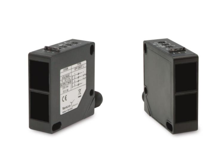
S PACEPAK SERIES
Some might say that the SpacePak series looks like many other sensors – and they are right. But that is as far as it goes. Having applied our many years of experience in photoelectric sensors, together with the latest technology, has ensured that this series is incomparable in terms of performance and precision – the difference comes from within.
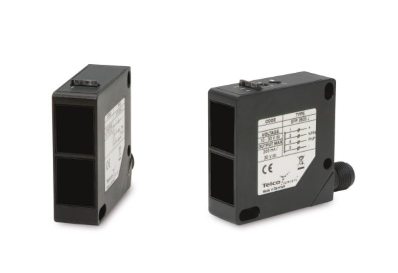
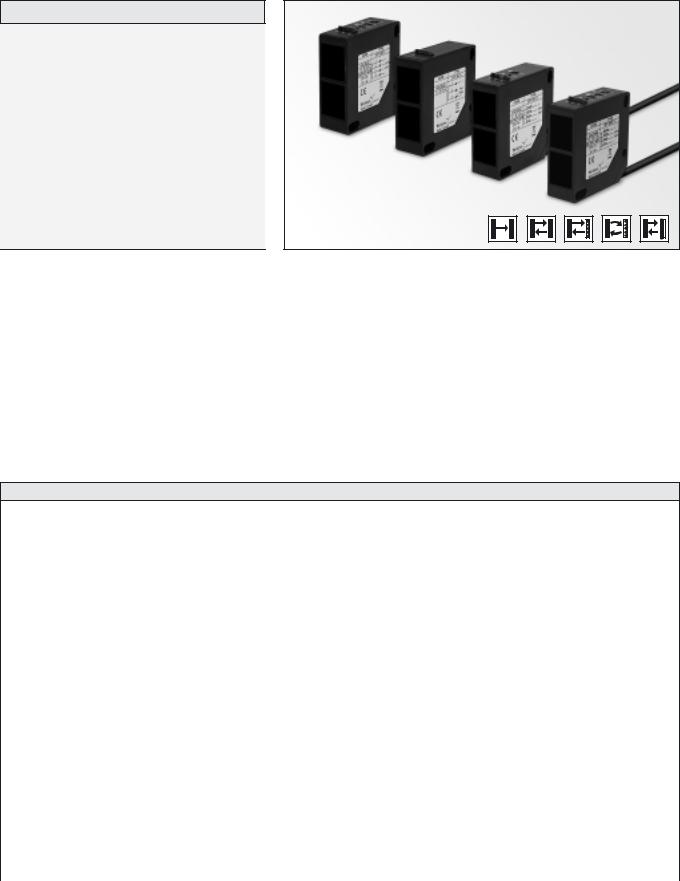
SPACEPAK™ SERIES |
SP 2000 |
|
|
Description
Operation mode and max sensing range:
Thru beam: 0 –45 m Diffuse proximity: 0 –3 m Retro reflective: 0 –12 m
Polarised retro reflective: 0 –10 m Background suppression: 0 –1.5 m
Compact rectangular housing (50 x 50 mm)
Cable or plug connection
Sensitivity adjustment via potentiometer
Switch selectable light or dark function
Adjustable on/off time delay
Power, output and signal level indicators
10-30 V dc or 12-240 V dc supply voltage
4 wire, NPN/PNP transistor output or 5 wire relay output
The SP 2000 series consists of a self-contained transmitter SPT and receiver SPR, which are to be used in thru beam mode, an SPP for diffuse proximity, SPRR for retro-reflective, SPPR for polarised retro reflective and SPBS for background suppression. All are offered with sensitivity adjustment via integral potentiometer with either cable or rotatable plug connection.
The complete series is available either as a 4 wire, NPN/PNP transistor output with 10-30 V dc supply voltage or as a 5 wire, relay output with a 12-240 V ac/dc supply voltage both offering switch selectable light or dark function and potentiometer adjustable 0 -10 sec on/off time delay.
The test input in the 10-30 V dc, SPT is intended to be used for disabling or enabling the transmitter power temporarily for test purposes or for multiplexing applications.
The dc series is protected against reverse polarity of power supplies, test input and output signals. The output is protected against short circuit and inductive loads.
Technical Data
|
|
SPT |
SPR |
SPP |
|
SPRR |
|
SPPR |
SPBS |
|
|
|
|
|
|
|
|
|
|
Supply voltage |
ac/dc |
|
|
12-240 V dc / 20-240 V ac |
|
|
|||
|
|
|
|
|
|
|
|
|
|
dc |
|
|
10 – 30 V dc |
|
|
||||
|
|
|
|
|
|||||
|
|
|
|
|
|
|
|
|
|
Voltage ripple |
|
|
|
|
+/– 15 % |
|
|
||
|
|
|
|
|
|
|
|
||
Output |
Relay |
– |
|
1 open / 1 close, 240 V ac / 3 A |
|
||||
Transistor |
|
|
|
|
|
|
|
|
|
– |
|
|
|
200 mA / 30 V dc |
|
|
|||
|
|
|
|
|
|
||||
|
|
|
|
|
|
|
|
|
|
Reverse polarity protected |
dc |
|
|
|
Yes |
|
|
||
|
|
|
|
|
|
|
|
|
|
Short circuit protected |
dc |
– |
|
|
|
Yes |
|
|
|
|
|
|
|
|
|
|
|
|
|
Current consumption |
ac |
|
|
|
< 70 mA |
|
|
||
dc |
|
|
|
|
|
|
|
|
|
|
|
|
< 65 mA |
|
|
||||
|
|
|
|
|
|
||||
|
|
|
|
|
|
|
|
|
|
Maximum operation frequency |
ac |
– |
|
|
|
25 Hz |
|
|
|
|
|
|
|
|
|
|
|
|
|
dc |
– |
|
|
|
250 Hz |
|
|
||
|
|
|
|
|
|
||||
|
|
|
|
|
|
|
|
|
|
Response time tON / tOFF |
ac |
– |
|
|
|
20 ms / 20 ms |
|
|
|
dc |
|
|
|
|
|
|
|
|
|
– |
|
|
|
2 ms / 2 ms |
|
|
|||
|
|
|
|
|
|
||||
|
|
|
|
|
|
|
|
|
|
Delay tON / tOFF |
|
– |
|
|
0 – 10 sec, adjustable |
|
|
||
Power on indicator |
|
|
|
Green LED |
|
|
|||
|
|
|
|
|
|
|
|
|
|
Output indicator |
|
– |
|
|
|
Yellow LED |
|
|
|
|
|
|
|
|
|
|
|
|
|
Signal status indicator |
|
– |
|
|
|
Red LED |
|
|
|
|
|
|
|
|
|
|
|
|
|
Hysteresis |
|
– |
20 – 30 % |
5 – 15 % |
|
Approx. 11 % |
|
Approx. 11 % |
3 – 10 % |
|
|
|
|
|
|
|
|
|
|
Light source |
|
Infra Red |
– |
Infra Red (880 nm) |
|
Visible Red |
Infra Red |
||
|
(880 nm) |
|
(670 nm) |
(880 nm) |
|||||
|
|
|
|
|
|
|
|||
|
|
|
|
|
|
|
|
|
|
Opening angle |
|
– |
+/– 2,5° |
+/– 5° |
|
+/– 1,5° |
+/– 5° |
||
|
|
|
|
|
|
|
|
|
|
Emission angle |
|
+/– 2° |
– |
+/– 1,5° |
|
+/– 2° |
+/– 1,5° |
||
|
|
|
|
|
|
|
|
|
|
Housing material |
|
|
|
|
|
Polycarbonate |
|
|
|
|
|
|
|
|
|
|
|
|
|
SELF-CONTAINED PHOTOELECTRIC SYSTEMS I 93

SP 2000 |
|
|
|
|
|
|
|
|
SPACEPAK™ SERIES |
|||||
|
|
|
|
|
|
|
|
|
|
|
|
|
|
|
|
|
|
|
|
|
|
|
|
|
|
|
|
|
|
Environmental Data |
|
|
|
|
|
|
|
|
|
|
|
|||
|
|
|
|
|
|
SPT |
SPR |
SPP |
|
SPRR |
|
SPPR |
SPBS |
|
|
|
|
|
|
|
|
|
|
|
|
|
|
|
|
Vibration |
|
|
|
|
|
|
10 – 55 Hz, 0.5 mm |
|
|
|
||||
|
|
|
|
|
|
|
|
|
|
|
|
|
|
|
Shock |
|
|
|
|
|
|
30 g |
|
|
|
|
|
||
|
|
|
|
|
|
|
|
|
|
|
|
|
|
|
Light immunity |
@ 5º incidence |
– |
25 000 lux |
– |
|
|
|
25 000 lux |
– |
|||||
|
|
|
|
|
|
|
|
|
|
|
|
|
|
|
|
|
|
|
@ 15º incidence |
– |
– |
25 000 lux |
|
|
|
– |
25 000 lux |
||
|
|
|
|
|
|
|
|
|
|
|
|
|
||
Temperature, operation |
|
|
|
|
– 20 to +55 º C |
|
|
|
||||||
|
|
|
|
|
|
|
|
|
|
|
|
|
||
Temperature, storage |
|
|
|
|
– 40 to +80 º C |
|
|
|
||||||
|
|
|
|
|
|
|
|
|
|
|
|
|
|
|
Sealing class |
|
|
|
|
IP 67 |
|
|
|
|
|
||||
|
|
|
|
|
|
|
|
|
|
|
|
|
|
|
Approvals |
|
|
|
ac |
|
|
a |
|
|
|
|
|
||
|
|
|
dc |
|
|
|
|
|
|
|
|
|
||
|
|
|
|
|
a |
|
|
|
|
|
||||
|
|
|
|
|
|
|
|
|
|
|
|
|||
|
|
|
|
|
|
|
|
|
|
|
|
|
|
|
|
|
|
|
|
|
|
|
|
|
|
|
|
|
|
Available Types |
|
|
|
|
|
|
|
|
|
|
|
|||
|
|
Type |
|
Power |
Control |
Time Delay |
Connection |
5 m cable |
|
|
4 pin, M12 Plug |
Range |
||
|
|
|
|
|
|
|
|
|
|
|||||
Transmitter |
|
|
Supply |
Feature |
Output |
|
Order Reference |
|||||||
|
|
|
|
|
|
|||||||||
|
|
|
|
|
|
|
||||||||
|
|
|
|
|
|
|
|
|
|
|
|
|
|
|
|
|
2645 |
|
10 – 30 |
Test input |
– |
– |
SPT 2645 5 |
|
|
SPT 2645 J |
|
||
|
|
|
V dc |
|
|
|
||||||||
|
|
|
|
|
|
|
|
|
|
|
|
|
45 m |
|
|
|
|
|
|
|
|
|
|
|
|
|
|
|
|
|
|
2945 |
|
12 – 240 |
– |
– |
– |
SPT 2945 5 |
|
|
SPT 2945 J |
|||
|
|
|
|
|
|
|||||||||
|
|
|
V ac / dc |
|
|
|
||||||||
|
|
|
|
|
|
|
|
|
|
|
|
|
|
|
|
|
|
|
|
|
|
|
|
|
|
|
|
||
|
|
|
|
|
|
|
|
|
|
|
|
|
||
|
|
2645 |
|
10 – 30 |
Sensitivity |
On/Off Delay |
NPN/PNP |
SPR 2645T 5 |
|
|
SPR 2645T J |
|
||
Receiver |
|
|
|
|
|
|
|
|
|
|
||||
|
|
12 – 240 |
light/dark |
On/Off Delay |
SPR 2945T 5 |
|
|
|
– |
|
||||
|
|
|
|
V dc |
potentiometer |
– |
|
SPR 2645 5 |
|
|
SPR 2645 J |
|
||
|
|
|
|
|
and |
|
|
|
0-45 m |
|||||
|
|
|
|
|
|
|
|
|
|
|
|
|
||
|
|
2945 |
|
|
|
Relay |
|
|
|
|
|
|
||
|
|
|
V ac / dc |
switch |
|
|
|
|
|
|
|
|
||
|
|
|
– |
SPR 2945 5 |
|
|
|
– |
|
|||||
|
|
|
|
|
|
|
|
|
|
|||||
|
|
|
|
|
|
|
|
|
|
|
||||
|
|
|
|
|
|
|
|
|
|
|
|
|
||
|
|
|
|
|
|
|
|
|
|
|
|
|
||
|
|
2603 |
|
10 – 30 |
Sensitivity |
On/Off Delay |
NPN/PNP |
SPP 2603T 5 |
|
|
SPP 2603T J |
|
||
Diffuse Proximity |
|
|
|
|
|
|
|
|
|
|
||||
|
2903 |
|
12 – 240 |
potentiometer |
– |
Relay |
SPP 2603 5 |
|
|
SPP 2603 J |
|
|||
|
|
|
|
V dc |
|
|
|
0-3 m |
||||||
|
|
|
|
|
and |
On/Off Delay |
|
SPP 2903T 5 |
|
|
|
– |
||
|
|
|
|
|
light/dark |
|
|
|
|
|
||||
|
|
|
|
V ac / dc |
switch |
|
|
|
|
|
|
|
|
|
|
|
|
|
– |
|
SPP 2903 5 |
|
|
|
– |
|
|||
|
|
|
|
|
|
|
|
|
|
|||||
|
|
|
|
|
|
|
|
|
|
|
||||
|
|
|
|
|
|
|
|
|
|
|
|
|
|
|
|
|
|
|
|
|
|
|
|
|
|
|
|
||
Reflective-Retro |
|
|
|
V ac / dc |
|
– |
|
SPRR 2912 5 |
|
|
|
– |
|
|
|
|
2612 |
|
10 – 30 |
Sensitivity |
On/Off Delay |
NPN/PNP |
SPRR 2612T 5 |
|
|
SPRR 2612T J |
|
||
|
|
|
|
V dc |
potentiometer |
– |
|
SPRR 2612 5 |
|
|
SPRR 2612 J |
|
||
|
|
|
|
|
and |
On/Off Delay |
|
SPRR 2912T 5 |
|
|
|
– |
0-12 m |
|
|
|
2912 |
|
12 – 240 |
light/dark |
Relay |
|
|
|
|
||||
|
|
|
switch |
|
|
|
|
|
|
|
|
|||
|
|
|
|
|
|
|
|
|
|
|
|
|||
|
|
|
|
|
|
|
|
|
|
|
|
|
||
Note: Reflector to be ordered separately |
|
|
|
|
|
|
|
|
|
|||||
|
|
|
|
|
|
|
|
|
|
|
|
|
||
Polarised Reflective-Retro |
|
|
|
V ac / dc |
|
– |
|
SPPR 2910 5 |
|
|
|
– |
|
|
|
|
2610 |
|
10 – 30 |
Sensitivity |
On/Off Delay |
NPN/PNP |
SPPR 2610T 5 |
|
|
SPPR 2610T J |
|
||
|
|
|
|
V dc |
potentiometer |
– |
|
SPPR 2610 5 |
|
|
SPPR 2610 J |
0-10 m |
||
|
|
|
|
|
and |
On/Off Delay |
|
SPPR 2910T 5 |
|
|
|
– |
||
|
|
2910 |
|
12 – 240 |
light/dark |
Relay |
|
|
|
|
||||
|
|
|
switch |
|
|
|
|
|
|
|
|
|||
|
|
|
|
|
|
|
|
|
|
|
|
|||
|
|
|
|
|
|
|
|
|
|
|
|
|
|
|
|
|
|
|
|
|
|
|
|
|
|
|
|
||
Note: Reflector to be ordered separately |
|
|
|
|
|
|
|
|
|
|||||
|
|
|
|
|
|
|
|
|
|
|
|
|
||
Background Suppression |
|
2901 |
|
10 – 30 |
switch |
On/Off Delay |
Relay |
SPBS 2601T 5 |
|
|
SPBS 2601T J |
|
||
|
|
|
|
|
|
|
|
|
|
|||||
|
|
2601 |
|
Sensitivity |
|
NPN/PNP |
|
|
|
|
|
|
|
|
|
|
|
|
V dc |
potentiometer |
– |
|
SPBS 2601 5 |
|
|
SPBS 2601 J |
0-1,5 m |
||
|
|
|
|
|
and |
|
|
|
|
|
|
|
|
|
|
|
|
|
|
On/Off Delay |
|
SPBS 2901T 5 |
|
|
|
– |
|||
|
|
|
|
12 – 240 |
light/dark |
|
|
|
|
|
||||
|
|
|
|
|
|
|
|
|
|
|
|
|
|
|
|
|
|
|
V ac / dc |
|
– |
|
SPBS 2901 5 |
|
|
|
– |
|
|
|
|
|
|
|
|
|
|
|
|
|
||||
|
|
|
|
|
|
|
|
|
|
|
|
|
|
|
94 I SELF-CONTAINED PHOTOELECTRIC SYSTEMS
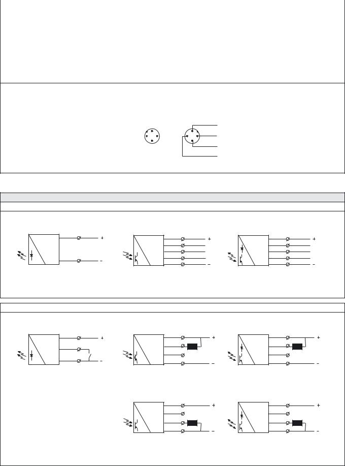
SPACEPAK™ SERIES |
|
SP 2000 |
|
|
|
|
|
|
|
|
|
Connections |
|
|
|
|
Cable |
M12 Plug / Cable |
|
|
|
|
|
Supply + |
Brown |
Pin 1 / Brown |
|
|
|
|
|
Supply – |
Blue |
Pin 3 / Blue |
|
|
|
|
|
SPT test input |
Black |
Pin 4 / Black |
|
|
|
|
|
Output NPN |
White |
Pin 2 / White |
|
|
|
|
|
Output PNP |
Black |
Pin 4 / Black |
|
|
|
|
|
Output NC |
Grey |
– |
|
|
|
|
|
Output NO |
Black |
– |
|
|
|
|
|
Output C |
White |
– |
|
|
|
|
|
4 pin, M12
Sensor Plug |
Cable Plug |
(Male) |
(Female) |
|
Brown |
|
1 |
|
1 |
2 |
4 |
4 |
2 |
|
3 |
|
3 |
White
Blue
Black
Wiring Diagrams
AC/DC Models
Brown |
Brown |
|
Brown |
|
|
|
|
|
|||
|
Grey |
NC |
Grey |
NC |
|
|
White |
White |
|||
|
C |
C |
|||
|
Black |
Black |
|||
Blue |
NO |
NO |
|||
Blue |
Blue |
||||
|
|
|
|||
SPT 2945 |
SPR 2945 |
|
SPP/SPRR/SPPR/SPBS 29xx |
|
DC Models
Brown |
1 |
Brown |
1 |
|
Black |
4 |
White |
2 Load |
|
Test |
|
|||
|
|
4 |
||
|
|
Black |
||
Blue |
3 |
|
NC |
|
Blue |
3 |
|||
|
|
|||
|
|
|
||
SPT 2645 |
|
SPR 2645 (load as NPN) |
||
Brown |
1 |
|
White |
2 |
NC |
|
||
|
|
|
Black |
4 |
|
Blue |
3 |
Load |
Brown |
1 |
|
White |
2 |
Load |
|
|
|
Black |
4 |
NC |
|
|
|
Blue |
3 |
|
|
|
SPP/SPRR/SPPR/SPBS 26xx (load as NPN)
Brown |
1 |
|
White |
2 |
NC |
|
||
|
|
|
Black |
4 |
|
Blue |
3 |
Load |
SPR 2645 (load as PNP) |
SPP/SPRR/SPPR/SPBS 2645 (load as PNP) |
SELF-CONTAINED PHOTOELECTRIC SYSTEMS I 95
SP 2000 |
|
|
|
|
|
|
SPACEPAK™ SERIES |
|
Dimensions and Descriptions |
|
|
|
|
|
|
|
|
10,5 |
|
4 |
3 |
12 |
10,5 |
4 |
3 |
12 |
2 |
|
|
|
|
2 |
|
|
|
|
6,5 |
|
|
|
|
6,5 |
|
|
|
23 |
|
|
|
|
23 |
|
|
50 |
|
|
|
|
50 |
|
|
|
|
Ø 4 |
|
|
|
|
Ø 4 |
|
|
|
M12 x 1 |
|
|
4 |
|
|
|
4 |
|
|
|
|
|
|
|
|
|
16 |
14 |
31,5 |
|
10 |
16 |
|
31,5 |
10 |
|
|
50 |
|
|
|
|
50 |
|
|
|
|
|
Power on indicator |
|
|
|
Power on indicator |
|
SPT 2645 J |
|
|
|
SPT 2x45 5 |
|
||
10,5 |
|
4 |
3 |
12 |
10,5 |
4 |
3 |
12 |
2 |
|
|
|
|
2 |
|
|
|
|
6,5 |
|
|
|
|
6,5 |
|
|
|
23 |
|
|
|
|
23 |
|
|
50 |
|
|
|
|
50 |
|
|
|
|
Ø 4 |
|
|
|
|
Ø 4 |
|
|
|
M12 x 1 |
|
|
4 |
|
|
|
4 |
|
|
|
|
|
|
|
|
|
16 |
14 |
31,5 |
|
10 |
16 |
|
31,5 |
10 |
|
|
50 |
|
|
|
|
50 |
|
|
|
|
|
Signal status indicator |
|
|
|
Signal status indicator |
|
|
|
|
Output indicator |
|
|
|
Output indicator |
|
|
|
|
Power on indicator |
|
|
|
Power on indicator |
|
|
|
|
Sensitivity adjustment |
|
|
|
Sensitivity adjustment |
|
|
|
|
Light/dark switch |
|
|
|
Light/dark switch |
|
SPR/SPP/SPRR/SPPR/SPBS 26xx J |
|
SPR/SPP/SPRR/SPPR/SPBS 2xxx 5 |
|||||
10,5 |
|
4 |
3 |
12 |
10,5 |
4 |
3 |
12 |
2 |
|
|
|
|
2 |
|
|
|
|
6,5 |
|
|
|
|
6,5 |
|
|
|
23 |
|
|
|
|
23 |
|
|
50 |
|
|
|
|
50 |
|
|
|
|
Ø 4 |
|
|
|
|
Ø 4 |
|
|
|
M12 x 1 |
|
|
4 |
|
|
|
4 |
|
|
|
|
|
|
|
|
|
16 |
14 |
31,5 |
|
10 |
16 |
|
31,5 |
10 |
|
|
50 |
|
|
|
|
50 |
|
|
|
|
|
Signal status indicator |
|
|
|
Signal status indicator |
|
|
|
|
Output indicator |
|
|
|
Output indicator |
|
|
|
|
Power on indicator |
|
|
|
Power on indicator |
|
Off delay adjustment |
|
|
Sensitivity adjustment |
|
Off delay adjustment |
|
Sensitivity adjustment |
|
On delay adjustment |
|
|
Light/dark switch |
|
On delay adjustment |
|
Light/dark switch |
|
SPR/SPP/SPRR/SPPR/SPBS 26xxT J |
|
SPR/SPP/SPRR/SPPR/SPBS 2xxxT 5 |
|||||
(Units in mm)
96 I SELF-CONTAINED PHOTOELECTRIC SYSTEMS
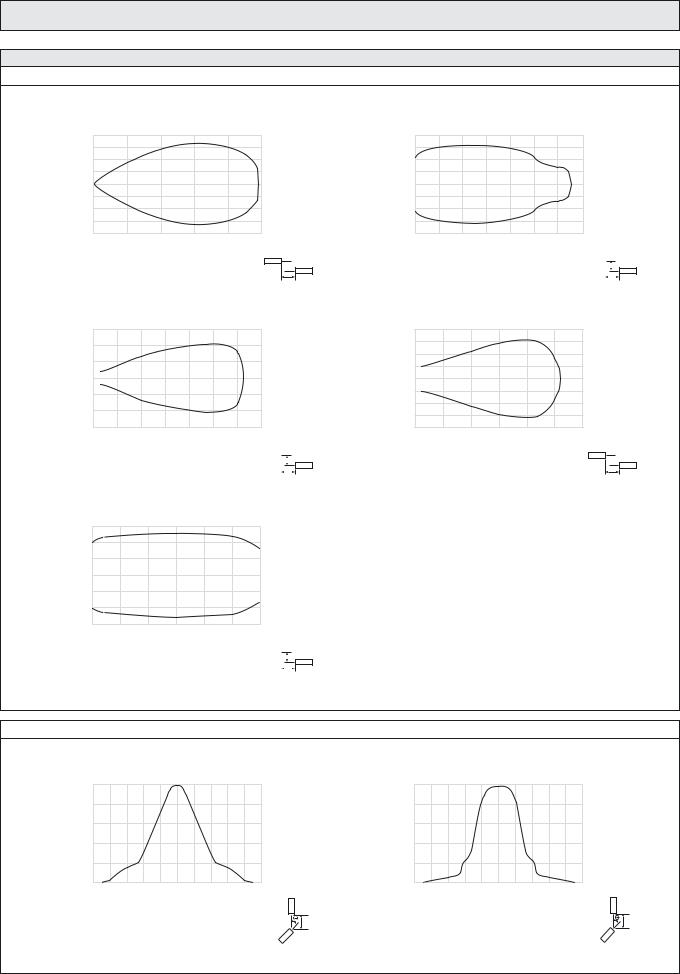
SPACEPAK™ SERIES
Sensing Characteristics
Parallel Displacement
|
1,00 |
(m) |
0,75 |
0,50 |
|
Displacement |
0,25 |
|
0 |
–0,25
–0,50
–0,75
–1,00
0 |
10 |
20 |
30 |
40 |
50 |
Range (m)
 Y
Y
SPT 2x45 and SPR 2x45
X
|
0,30 |
|
(m) |
0,20 |
|
0,10 |
||
Displacement |
||
0 |
||
|
– 0,10
– 0,20
–0,30
0 |
2 |
4 |
6 |
8 |
10 |
12 |
14 |
|
|
|
||
|
|
|
Range (m) |
|
|
|
|
|
|
|
|
|
|
|
|
SPRR 2x12 |
|
|
|
|
|
|
|
Y |
|
|
|
|
|
|
|
|
|
|
|
|
||
|
|
|
|
|
|
|
|
|
X |
|||
|
|
|
|
|
|
|
|
|
|
|
||
|
0,15 |
|
(m) |
0,10 |
|
0,05 |
||
Displacement |
||
0 |
||
|
||
|
–0,05 |
–0,10
–0,15
0 |
0,25 |
0,50 |
0,75 |
1,00 |
1,25 |
1,50 |
|
|
|
||
|
|
|
Range (m) |
|
|
|
|
|
|
|
|
|
|
SPBS 2x01 |
|
|
|
|
|
|
|
Y |
|
|
|
|
|
|
|
|
|
|
|
||
|
|
|
|
|
|
|
|
X |
|||
|
|
|
|
|
|
|
|
|
|
||
Angular Displacement
|
50 |
|
|
40 |
|
(m) |
30 |
|
Range |
||
20 |
||
|
||
|
10 |
|
|
0 |
–10 –8 –6 –4 –2 0 2 4 6 8 10 Degrees
Y
SPT
Telco reserves the right to change specifications without notice.
SP 2000
|
0,20 |
(m) |
0,15 |
0,10 |
|
Displacement |
0,05 |
|
0 |
–0,05
–0,10
–0,15
–0,20
0 |
0,5 |
1,0 |
1,5 |
2,0 |
2,5 |
3,0 |
3,5 |
|
|
|
|
|
|
|
|
Range (m) |
|
|
|
|
|
|
|
|
|
|
|
|
SPP 2x03 |
|
|
|
|
|
|
|
Y |
|
|
|
|
|
|
|
|
|
|
|
|
||
|
|
|
|
|
|
|
|
|
X |
|||
|
|
|
|
|
|
|
|
|
|
|
||
|
0,20 |
(m) |
0,15 |
0,10 |
|
Displacement |
0,05 |
|
|
|
0 |
–0,05
–0,10
–0,15
–0,20
0 |
2 |
4 |
6 |
8 |
10 |
12 |
Range (m)
 Y
Y
SPPR 2x10
X
|
50 |
|
|
40 |
|
(m) |
30 |
|
Range |
||
20 |
||
|
||
|
10 |
|
|
0 |
–10 –8 –6 –4 –2 0 2 4 6 8 10 Degrees
Y
SPR
SELF-CONTAINED PHOTOELECTRIC SYSTEMS I 97

SPACEGUARD SERIES
The SpaceGuard series has never been anything less than impressive. The slim, but durable, design of our detectors has never failed to raise eyebrows. Yet this signature design has never hindered nor compromised its technology or performance in any way – on the contrary, it has motivated creative and innovative engineering in every way.

SPACEGUARD™ SERIES |
SG 1 |
Description
0-4 metre sensing range
94 or 194 cross scanning beams
Active height of 1755 mm or 1800 mm
Detector length 2000 mm or 2100 mm
Flexible cable connection
Automatic sensitivity adjustment
Slim line (10 x 28 mm) or leading edge (37,5 x 13 mm) detector housing
Power, output and signal status indicators
12 – 36 V dc supply voltage
4 wire, NPN or PNP transistor output or
5 wire, solid state relay output
Test input
Time-out function via wire connection
The SG 1 light curtain system consists of a self-contained transmitter detector, SGT and receiver detector, SGR, which are to be positioned opposite of each other. The detectors are housed in an aluminium profile available in a slim line design (10 x 28 mm) and a leading edge design (37,5 x 13 mm).
The SGR is supplied with a 12 – 36 V dc power supply with a 4 wire, NPN or PNP transistor output, or a 5 wire, solid state relay output, with a choice of light or dark function. The test input in the SGT may be used for either disabling or enabling the transmitting power temporarily for test purposes.
The detectors also include time-out function, which when enabled,
allows a pre-set number of channels to be automatically ignored if permanently obstructed for 10 seconds or more. This function can be enabled or disabled via the connection.
The |
advanced automatic signal-tracking (AST) feature ensures that |
no |
onsite set up or adjustments are required. The signal level of |
each individual channel is adjusted automatically compensating for misalignment and contamination during operation. The system can be used both in static and dynamic installations.
Both the transmitter and receiver detectors are protected against reverse polarity of power supplies, control input and output signals. The output is also protected against short circuit and inductive loads.
Technical Data
|
46 mm channel spacing |
|
|
92 mm channel spacing |
||||
|
|
|
|
|
|
|
|
|
|
SGT |
|
SGR |
|
|
SGT |
|
SGR |
|
|
|
|
|
|
|
|
|
Supply voltage |
|
|
|
12 – 36 V dc |
|
|||
|
|
|
|
|
|
|
|
|
Current consumption |
Max. 100 mA |
|
50 mA |
|
|
Max. 100 mA |
|
50 mA |
|
|
|
|
|
|
|
|
|
Output rating |
– |
|
200 mA |
|
|
– |
|
200 mA |
|
|
|
|
|
|
|
|
|
Short circuit protected |
– |
|
Yes |
|
|
– |
|
Yes |
|
|
|
|
|
|
|
|
|
Reverse polarity protected |
|
|
|
|
Yes |
|
||
|
|
|
|
|
|
|
|
|
Light source |
Infrared (940 nm) |
|
– |
|
|
Infrared (940 nm) |
|
– |
|
|
|
|
|
|
|
|
|
Number of channels (diodes per detector) |
40 |
|
|
|
20 |
|
||
|
|
|
|
|
|
|
|
|
Number of cross scanning beams |
194 (constant) |
|
|
|
94 (constant) |
|
||
|
|
|
|
|
|
|
|
|
Active height |
1800 mm |
|
|
|
1755 mm |
|
||
|
|
|
|
|
|
|||
Channel spacing |
Between channel 1 and bottom of housing: 25 mm |
|
Between channel 1 and bottom of housing: 25 mm |
|||||
Between other channels: 46 mm |
|
|
Between other channels: 92 mm |
|||||
|
|
|
||||||
|
|
|
|
|
|
|
|
|
Distance between beams at pinch point |
23 mm |
|
|
|
46 mm |
|
||
|
|
|
|
|
|
|
|
|
Response time |
– |
|
< 80 ms |
|
|
– |
|
< 40 ms |
|
|
|
|
|
|
|
|
|
Power on indicator |
|
|
|
Green LED |
|
|||
|
|
|
|
|
|
|
|
|
Output indicator |
– |
|
Yellow LED |
|
|
– |
|
Yellow LED |
|
|
|
|
|
|
|
|
|
System status indicator |
– |
|
Red LED |
|
|
– |
|
Red LED |
|
|
|
|
|
|
|
||
Time-out function |
Up to 4 non-adjacent channels, selectable |
|
|
Up to 2 non-adjacent channels, selectable |
||||
|
|
|
|
|
|
|
||
Connection |
|
|
3 m fixed flexible cable |
|
||||
|
|
|
|
|
|
|
|
|
Slim Line |
|
|
|
10 x 28 mm |
|
|||
Housing dimensions (w x d) |
|
|
|
|
|
|
|
|
|
|
|
37,5 x 13 mm |
|
||||
Leading Edge |
|
|
|
|
||||
|
|
|
|
|
|
|
|
|
Housing material |
|
|
|
Aluminium |
|
|||
|
|
|
|
|
|
|
|
|
Housing colour |
|
|
|
Black anodized |
|
|||
|
|
|
|
|
|
|
||
Front cover |
|
|
Infrared transparent plastic |
|
||||
|
|
|
|
|
|
|
|
|
SELF-CONTAINED LIGHT CURTAIN SYSTEMS I 101

SG 1 |
|
|
|
|
|
|
|
SPACEGUARD™ SERIES |
|||
|
|
|
|
|
|
|
|
|
|
|
|
Environmental Data |
|
|
|
|
|
|
|
|
|||
Light immunity @ 5° incidence |
|
|
|
|
|
|
> 100 000 lux |
|
|||
|
|
|
|
|
|
|
|
|
|
|
|
Temperature, operation |
|
|
|
|
|
|
–20 to +65 °C |
|
|||
|
|
|
|
|
|
|
|
|
|
|
|
Temperature, storage |
|
|
|
|
|
|
–40 to +80 °C |
|
|||
|
|
|
|
|
|
|
|
|
|
|
|
Sealing class |
|
|
|
|
|
|
|
IP 54 |
|
||
|
|
|
|
|
|
|
|
|
|
|
|
Approvals |
|
|
|
|
|
|
|
a |
|
||
|
|
|
|
|
|
|
|
|
|
|
|
|
|
|
|
|
|
|
|
|
|
|
|
Available Types |
|
|
|
|
|
|
|
|
|
||
Detector |
Housing |
|
Active |
Number of |
Number of |
|
Beam |
Housing Design |
Slim Line |
Leading Edge |
|
|
|
1755 mm |
20 |
94 |
|
92 mm |
|
|
SGT 1-200-020-A-3F |
SGT 1-200-020-B-3F |
|
|
Length |
|
Height |
Channels |
Beams |
Spacing |
Output |
|
Order reference |
||
Transmitter |
2000 mm |
|
|
|
|
|
|
|
|
|
|
|
1800 mm |
40 |
194 |
|
46 mm |
|
|
SGT 1-210-040-A-3F |
SGT 1-210-040-B-3F |
||
|
|
|
|
|
|||||||
|
|
|
1800 mm |
40 |
194 |
|
46 mm |
– |
|
SGT 1-200-040-A-3F |
SGT 1-200-040-B-3F |
|
2100 mm |
|
1755 mm |
20 |
94 |
|
92 mm |
|
SGT 1-210-020-A-3F |
SGT 1-210-020-B-3F |
|
|
|
|
|
|
|||||||
|
|
|
|
|
|
|
|
|
|
|
|
|
|
|
|
|
|
|
|
|
|
|
|
|
|
|
|
|
|
|
|
|
|
|
|
|
|
|
|
|
|
|
|
|
|
|
|
|
|
|
|
|
|
|
|
NPN |
NC |
SGR 1-200-020-A-00-3F |
SGR 1-200-020-B-00-3F |
|
|
|
|
|
|
|
|
|
|
|
|
|
|
|
|
|
|
|
|
NO |
SGR 1-200-020-A-01-3F |
SGR 1-200-020-B-01-3F |
|
|
|
|
|
|
|
|
|
|
|||
|
|
|
|
|
|
|
|
|
|
|
|
|
|
|
1755 mm |
20 |
94 |
|
92 mm |
PNP |
NC |
SGR 1-200-020-A-02-3F |
SGR 1-200-020-B-02-3F |
|
|
|
|
|
|
|
|||||
|
|
|
|
NO |
SGR 1-200-020-A-03-3F |
SGR 1-200-020-B-03-3F |
|||||
|
|
|
|
|
|
|
|
|
|||
|
|
|
|
|
|
|
|
|
|
|
|
|
|
|
|
|
|
|
|
Solid State |
NO |
SGR 1-200-020-A-04-3F |
SGR 1-200-020-B-04-3F |
|
|
|
|
|
|
|
|
|
|
|
|
|
|
|
|
|
|
|
|
Relay |
NC |
SGR 1-200-020-A-05-3F |
SGR 1-200-020-B-05-3F |
|
2000 mm |
|
|
|
|
|
|
|
|||
|
|
|
|
|
|
|
|
|
|
|
|
|
|
|
|
|
|
|
NPN |
NC |
SGR 1-200-040-A-00-3F |
SGR 1-200-040-B-00-3F |
|
|
|
|
|
|
|
|
|
||||
|
|
|
|
|
|
|
|
|
|
|
|
|
|
|
|
|
|
|
|
NO |
SGR 1-200-040-A-01-3F |
SGR 1-200-040-B-01-3F |
|
|
|
|
|
|
|
|
|
|
|||
|
|
|
|
|
|
|
|
|
|
|
|
|
|
|
1800 mm |
40 |
194 |
|
46 mm |
PNP |
NC |
SGR 1-200-040-A-02-3F |
SGR 1-200-040-B-02-3F |
|
|
|
|
|
|
|
|||||
Detector |
|
|
|
NO |
SGR 1-200-040-A-03-3F |
SGR 1-200-040-B-03-3F |
|||||
|
|
|
|
|
|
|
|
||||
|
|
|
|
|
|
|
|
|
|
|
|
|
|
|
|
|
|
|
Solid State |
NO |
SGR 1-200-040-A-04-3F |
SGR 1-200-040-B-04-3F |
|
|
|
|
|
|
|
|
|
||||
|
|
|
|
|
|
|
|
|
|
|
|
|
|
|
|
|
|
|
|
Relay |
NC |
SGR 1-200-040-A-05-3F |
SGR 1-200-040-B-05-3F |
|
|
|
|
|
|
|
|
|
|||
Receiver |
|
|
|
|
|
|
|
|
|
|
|
|
|
|
|
|
|
|
NPN |
NC |
SGR 1-210-020-A-00-3F |
SGR 1-210-020-B-00-3F |
|
|
|
|
|
|
|
|
|
||||
|
|
|
|
|
|
|
|
|
|
|
|
|
|
|
|
|
|
|
|
NO |
SGR 1-210-020-A-01-3F |
SGR 1-210-020-B-01-3F |
|
|
|
|
|
|
|
|
|
|
|||
|
|
|
|
|
|
|
|
|
|
|
|
|
|
|
1755 mm |
20 |
94 |
|
92 mm |
PNP |
NC |
SGR 1-210-020-A-02-3F |
SGR 1-210-020-B-02-3F |
|
|
|
|
|
|
|
|||||
|
|
|
|
NO |
SGR 1-210-020-A-03-3F |
SGR 1-210-020-B-03-3F |
|||||
|
|
|
|
|
|
|
|
|
|||
|
|
|
|
|
|
|
|
|
|
|
|
|
|
|
|
|
|
|
|
Solid State |
NO |
SGR 1-210-020-A-04-3F |
SGR 1-210-020-B-04-3F |
|
|
|
|
|
|
|
|
|
|
|
|
|
|
|
|
|
|
|
|
Relay |
NC |
SGR 1-210-020-A-05-3F |
SGR 1-210-020-B-05-3F |
|
2100 mm |
|
|
|
|
|
|
|
|||
|
|
|
|
|
|
|
|
|
|
|
|
|
|
|
|
|
|
|
NPN |
NC |
SGR 1-210-040-A-00-3F |
SGR 1-210-040-B-00-3F |
|
|
|
|
|
|
|
|
|
||||
|
|
|
|
|
|
|
|
|
|
|
|
|
|
|
|
|
|
|
|
NO |
SGR 1-210-040-A-01-3F |
SGR 1-210-040-B-01-3F |
|
|
|
|
|
|
|
|
|
|
|||
|
|
|
|
|
|
|
|
|
|
|
|
|
|
|
1800 mm |
40 |
194 |
|
46 mm |
PNP |
NC |
SGR 1-210-040-A-02-3F |
SGR 1-210-040-B-02-3F |
|
|
|
|
|
|
|
|||||
|
|
|
|
NO |
SGR 1-210-040-A-03-3F |
SGR 1-210-040-B-03-3F |
|||||
|
|
|
|
|
|
|
|
|
|||
|
|
|
|
|
|
|
|
|
|
|
|
|
|
|
|
|
|
|
|
Solid State |
NO |
SGR 1-210-040-A-04-3F |
SGR 1-210-040-B-04-3F |
|
|
|
|
|
|
|
|
|
|
|
|
|
|
|
|
|
|
|
|
Relay |
NC |
SGR 1-210-040-A-05-3F |
SGR 1-210-040-B-05-3F |
|
|
|
|
|
|
|
|
|
|||
|
|
|
|
|
|
|
|
|
|
|
|
Note: 1. The transmitter SGT and receiver SGR set must have the same number of channels
2. The receiver SGR is available with an optional alarm output wire. Add AL after the type number for alarm output e.g. SGR 1-200-040-A-00-3F-AL
102 I SELF-CONTAINED LIGHT CURTAIN SYSTEMS
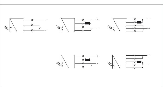
SPACEGUARD™ SERIES |
SG 1 |
|
|
|
|
Wiring Diagrams |
|
|
|
|
|
Brown |
|
Brown |
|
|
|
Black |
Load |
Black |
|
|
|
ON/OFF |
Blue |
|
|
|
|
||
|
Switch |
|
|
Blue |
|
|
|
|
White |
Time-out |
|
|
|
||
|
|
|
(Enable) |
SGT 1 |
|
SGR 1 (NPN Output) |
|
Brown |
|
Black |
|
Blue |
|
White |
Time-out |
|
(Enable) |
SGR 1 (PNP Output)
Brown |
|
Black |
Load |
|
|
Black |
|
Blue |
|
White |
Time-out |
|
(Enable) |
SGR 1 (Solid State Relay Output – load NPN)
Brown |
|
Black |
|
Black |
Load |
|
|
Blue |
|
White |
Time-out |
|
(Enable) |
SGR 1 (Solid State Relay Output – load PNP)
SELF-CONTAINED LIGHT CURTAIN SYSTEMS I 103

SG 1
Dimensions and Descriptions
Slim Line
|
Details |
Top Side View |
Top Rear View |
Cable |
Cable |
Rear |
Front |
Ø 4 
 System status indicator (SGR)
 Output indicator (SGR)
 Power on indicator (SGT/SGR)
3,5 |
|
|
Top View |
|
|
|
|
Mounting |
|
|
Slot 4,4 |
Bottom View |
Ø 8 |
|
|
||
14 |
Ø 8 |
|
17,5 |
|
10 |
|
|
|
28 |
|
|
Rear |
Front |
|
|
|
Ø 8 |
Positioning Pin |
|
20,5 |
|
||
10 |
(removable) |
||
|
|||
|
|
||
Bottom Side View |
Bottom Rear View |
||
SPACEGUARD™ SERIES
100
100 
50
50 
100
550
 Ø 8
Ø 8
50
2000
900 |
1050 |
|
100 
SGT/SGR |
SGT/SGR |
Side View |
Rear View |
SG 1-200
100 
100
100 
50
50 
100
550
Ø 8
2100
50
900
1050
100 |
|
SGT/SGR |
SGT/SGR |
Side View |
Rear View |
SG 1-210
(Units in mm)
104 I SELF-CONTAINED LIGHT CURTAIN SYSTEMS
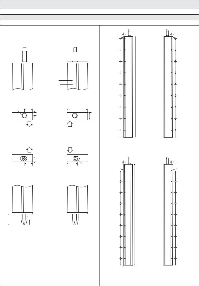
SPACEGUARD™ SERIES
Dimensions and Descriptions
Leading Edge
|
|
|
Details |
|||
|
SGT |
|
|
SGR |
||
|
Top Front View |
|
|
Top Front View |
||
|
Cable |
|
|
Cable |
||
|
|
|
|
|
|
|
System status indicator 
Output indicator
 Power on indicator
Top View |
Top View |
|
14,5 |
|
37,5 |
Ø 9 |
|
|
|
5,5 |
13 |
|
|
|
Transmitting |
|
Receiving |
direction |
|
direction |
Bottom View |
Bottom View |
|
Transmitting |
|
Receiving |
direction |
|
direction |
|
5,5 |
|
14,5 |
18 |
Ø 8 |
Bottom Front View |
Bottom Front View |
|
|
Ø 8 |
Positioning Pin |
20 |
|
|
|
(removable) |
|
|
10 |
|
|
|
SG 1
6 |
6 |
Ø 3 |
Ø 3 |
225 |
225 |
225 |
225 |
225 |
225 |
225 |
225 |
|
2000 |
225 |
225 |
225 |
225 |
225 |
225 |
225 |
225 |
152,5 |
152,5 |
SGR |
SGT |
Rear View |
Rear View |
|
SG 1-200 |
6 |
6 |
Ø 3 |
Ø 3 |
225 |
225 |
225 |
225 |
225 |
225 |
225 |
225 |
|
2100 |
225 |
225 |
225 |
225 |
225 |
225 |
225 |
225 |
152,5 |
152,5 |
SGR |
SGT |
Rear View |
Rear View |
|
SG 1-210 |
(Units in mm)
SELF-CONTAINED LIGHT CURTAIN SYSTEMS I 105
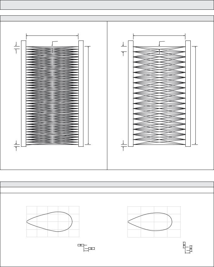
SG 1
Beam Patterns
0 – 4 000
Pinch point: 23
46
1800
25
46 mm beam spacing
Sensing Characteristics
Parallel Displacement
80
40
0
–40
–80
0 |
1 |
2 |
3 |
4 |
5 |
Range (m)
 Y
Y
Slim Line |
X |
Telco reserves the right to change specifications without notice.
SPACEGUARD™ SERIES
0 – 4 000
Pinch point: 46
92
1755
25
92 mm beam spacing
(Units in mm)
|
60 |
(cm) |
30 |
Displacement |
0 |
|
– 30
– 60
0 |
1 |
2 |
3 |
4 |
Range (m)
 Y
Y
Leading Edge
X
106 I SELF-CONTAINED LIGHT CURTAIN SYSTEMS
SPACEGUARD™ SERIES |
SG 2 |
Description
0-4 metre sensing range
94 cross scanning beams
Active height of 1800 mm
Detector length 2000 mm or 2100 mm
Flexible cable connection
Automatic sensitivity adjustment
Slim line (10 x 28 mm) detector housing
Power, output and signal status indicators
12 – 36 V dc supply voltage
Blanking function of up to 10 channels
5 wire, solid state relay output
Test input
Light/dark function via wire connection
The SG 2 light curtain system is designed for modernisation of elevator doors and consists of a self-contained transmitter detector, SGT and receiver detector, SGR, which are to be positioned opposite of each other. The detectors are housed in an aluminium profile available in a slim line design (10 x 28 mm).
The SGR is supplied with a 12 – 36 V dc power supply with a 5 wire, solid state relay output and with wire selectable light or dark function. The test input in the SGT may be used for either disabling or enabling the transmitting power temporarily for test purposes.
The detectors are available with time-out function which allows up to 2 channels to be ignored if permanently obstructed for 10 seconds or more.
The advanced automatic signal-tracking (AST) feature ensures that no onsite set up or adjustments are required. The signal level of each individual channel is adjusted automatically compensating for misalignment and contamination during operation. The system can be used both in static and dynamic applications.
The special blanking function allows up to 10 top channels to be ignored when covered during set up. This feature allows the active height to be reduced for applications which do not allow the full detection height.
Both the transmitter and receiver detectors are protected against reverse polarity of power supplies, control input and output signals. The output is also protected against short circuit and inductive loads.
Technical Data
|
SGT |
|
SGR |
|
|
|
|
|
|
Supply voltage |
|
12 – 36 V dc |
||
|
|
|
|
|
Current consumption |
Max. 100 mA |
|
50 mA |
|
|
|
|
|
|
Output rating |
– |
|
200 mA |
|
|
|
|
|
|
Short circuit protected |
– |
|
Yes |
|
|
|
|
|
|
Reverse polarity protected |
|
Yes |
||
|
|
|
|
|
Light source |
Infrared (880 nm) |
|
– |
|
|
|
|
|
|
Number of channels (diodes per detector) |
|
20 |
||
|
|
|
|
|
Number of cross scanning beams |
|
94 (constant) |
||
|
|
|
|
|
Active height |
|
1800 mm |
||
|
|
|
||
Channel spacing |
Between channel 1 and bottom of housing: 25 mm |
|||
Between channel 19 and channel 20: 138 mm |
||||
|
||||
|
|
Between other channels: 92 mm |
||
|
|
|
|
|
Distance between beams at pinch point |
|
46 mm |
||
|
|
|
|
|
Response time |
– |
|
< 40 ms |
|
|
|
|
|
|
Power on indicator |
|
Green LED |
||
|
|
|
|
|
Output indicator |
– |
|
Yellow LED |
|
|
|
|
|
|
System status indicator |
– |
|
Red LED |
|
|
|
|
|
|
Time-out function |
|
Up to 2 non-adjacent channels |
||
|
|
|
|
|
Connection |
|
3 m fixed flexible cable |
||
|
|
|
|
|
Housing dimensions (w x d) |
|
10 x 28 mm |
||
|
|
|
|
|
Housing material |
|
Aluminium |
||
|
|
|
|
|
Housing colour |
|
Natural anodized |
||
|
|
|
|
|
Front cover |
|
Infrared transparent plastic |
||
|
|
|
|
|
SELF-CONTAINED LIGHT CURTAIN SYSTEMS I 107
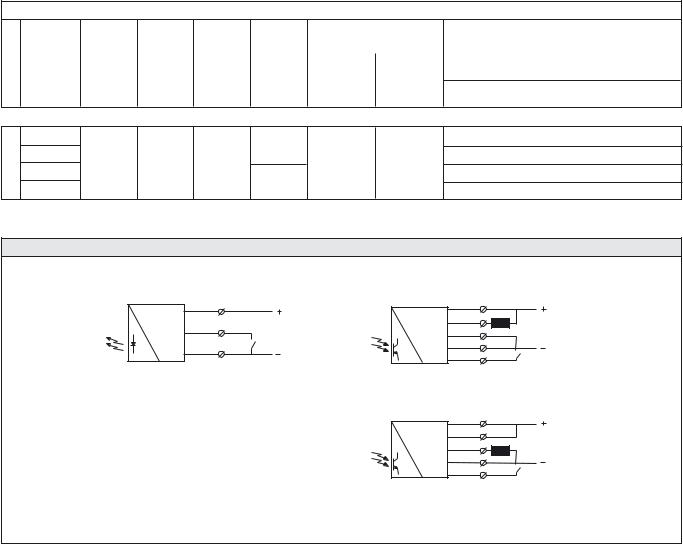
SG 2 |
SPACEGUARD™ SERIES |
|
|
Environmental Data |
|
Light immunity @ 5° incidence |
> 100 000 lux |
|
|
Temperature, operation |
–20 to +65 °C |
|
|
Temperature, storage |
–40 to +80 °C |
|
|
Sealing class |
IP 54 |
|
|
Approvals |
a |
|
|
|
|
Available Types |
|
|
|
Transmitter
Housing |
Active |
Number of |
Number of |
Time-Out |
Housing Design |
Slim Line |
Length |
Height |
Channels |
Beams |
Function |
Output |
Order reference |
|
|
|
|
|
|
|
2000 mm |
|
|
|
|
|
SGT 2-200-020-010-A-00-3F |
|
1800 mm |
20 |
94 |
– |
– |
– |
|
||||||
2100 mm |
|
|
|
|
|
SGT 2-210-020-010-A-00-3F |
Receiver
2000 mm |
|
|
Time-Out |
SGR 2-200-020-010-A-06-3F |
|
2100 mm |
|
|
SGR 2-210-020-010-A-06-3F |
||
|
|
Solid State |
|||
1800 mm |
20 |
94 |
NO/NC |
||
Relay |
|||||
2000 mm |
|
|
SGR 2-200-020-010-A-07-3F |
||
2100 mm |
|
|
– |
SGR 2-210-020-010-A-07-3F |
|
|
|
|
Wiring Diagrams
Brown |
Black |
ON/OFF |
Switch |
Blue |
SGT 2
Brown
Black Load
Black
Blue
White
Light/Dark
SGR 2 (load as NPN)
Brown |
|
Black |
|
Black |
Load |
|
|
Blue |
|
White |
Light/Dark |
|
SGR 2 (load as PNP)
108 I SELF-CONTAINED LIGHT CURTAIN SYSTEMS
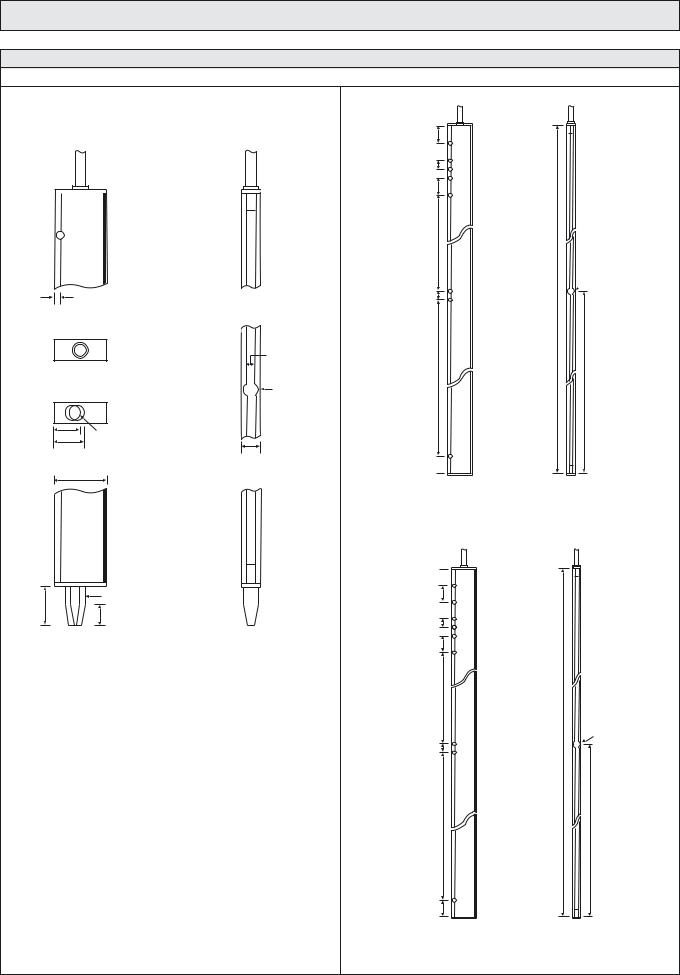
SPACEGUARD™ SERIES
Dimensions and Descriptions
Slim Line
|
Details |
Top Side View |
Top Rear View |
Cable |
Cable |
Rear |
Front |
Ø 4 
 System status indicator (SGR)
 Output indicator (SGR)
 Power on indicator (SGT/SGR)
3,5 |
|
|
Top View |
|
|
|
|
Mounting |
|
|
Slot 4,4 |
Bottom View |
Ø 8 |
|
|
||
14 |
Ø 8 |
|
17,5 |
|
10 |
|
|
|
28 |
|
|
Rear |
Front |
|
|
|
Ø 8 |
Positioning Pin |
|
20,5 |
|
||
10 |
(removable) |
||
|
|||
|
|
||
Bottom Side View |
Bottom Rear View |
||
SG 2
100
100 
50
50 
100
550
 Ø 8
Ø 8
50
2000
900 |
1050 |
|
100 
SGT/SGR |
SGT/SGR |
Side View |
Rear View |
SG 2-200
100 
100
100 
50
50 
100
550
Ø 8
2100
50
900
1050
100 |
|
SGT/SGR |
SGT/SGR |
Side View |
Rear View |
SG 2-210
(Units in mm)
SELF-CONTAINED LIGHT CURTAIN SYSTEMS I 109

SG 2 |
SPACEGUARD™ SERIES |
|
|
|
|
Beam Patterns |
|
|
|
|
|
0 – 4 000
 Pinch point: 46
1800
1660
1570
1475
1385
1295
1200
1115
1015
925
835
25
(Units in mm)
Sensing Characteristics
Parallel Displacement
Displacement (cm)
80
40
0
–40
–80
0 |
1 |
2 |
3 |
4 |
5 |
Range (m)
 Y
Y
Slim Line |
X |
Telco reserves the right to change specifications without notice.
110 I SELF-CONTAINED LIGHT CURTAIN SYSTEMS

SPACEGUARD™ SERIES |
SG 10 |
Description
1-10 metre sensing range
34 to 194 cross scanning beams
Active height of 650 mm to 1800 mm
Detector length of 850 mm to 2000 mm
Cable connection
Automatic sensitivity adjustment
Weather resistant, slim line (12 x 30 mm) detector housing
Power, output and signal status indicators
12 – 36 V dc supply voltage
5 wire, solid state relay output
Test input
The SG 10 light curtain system consists of a self-contained transmitter detector, SGT and receiver detector, SGR, which are to be positioned opposite of each other. The detectors are housed in a weather resistant, aluminium profile available in a slim line design (12 x 30 mm).
The SGR is supplied with a 12 – 36 V dc power supply with a 5 wire, solid state relay output, with wire selectable light or dark function. The test input in the SGT may be used for either disabling or enabling the transmitting power temporarily for test purposes.
The advanced automatic signal-tracking (AST) feature ensures that no onsite set up or adjustments are required. The signal level of each individual channel is adjusted automatically, which compensates for misalignment and contamination during operation.
Both the transmitter and receiver detectors are protected against reverse polarity of power supplies, control input and output signals. The output is also protected against short circuit and inductive loads.
Technical Data
|
46 mm channel spacing |
|
|
92 mm channel spacing |
||||
|
|
|
|
|
|
|
|
|
|
SGT |
|
SGR |
|
|
SGT |
|
SGR |
|
|
|
|
|
|
|
|
|
Supply voltage |
|
|
|
12 – 36 V dc |
|
|||
|
|
|
|
|
|
|
|
|
Current consumption |
Max. 100 mA |
|
50 mA |
|
|
Max. 100 mA |
|
50 mA |
|
|
|
|
|
|
|
|
|
Output rating |
– |
|
200 mA |
|
|
– |
|
200 mA |
|
|
|
|
|
|
|
|
|
Short circuit protected |
– |
|
Yes |
|
|
– |
|
Yes |
|
|
|
|
|
|
|
|
|
Reverse polarity protected |
|
|
|
|
Yes |
|
||
|
|
|
|
|
|
|
|
|
Light source |
Infrared (880 nm) |
|
– |
|
|
Infrared (880 nm) |
|
– |
|
|
|
|
|
|
|
|
|
Number of channels (diodes per detector) |
16, 24, 32 or 40 |
|
|
|
8, 12, 16 or 20 |
|
||
|
|
|
|
|
|
|
|
|
Number of cross scanning beams |
74, 114, 154 or 194 |
|
|
34, 54, 74 or 94 |
|
|||
|
|
|
|
|
|
|
||
Active height |
695, 1065, 1430 or 1800 mm |
|
|
650, 1020, 1385 or 1755 mm |
||||
|
|
|
|
|
|
|||
Channel spacing |
Between channel 1 and bottom of housing: 25 mm |
|
Between channel 1 and bottom of housing: 25 mm |
|||||
Between other channels: 46 mm |
|
|
Between other channels: 92 mm |
|||||
|
|
|
||||||
|
|
|
|
|
|
|
|
|
Distance between beams at pinch point |
23 mm |
|
|
|
46 mm |
|
||
|
|
|
|
|
|
|
|
|
Response time |
– |
|
< 165 ms |
|
|
– |
|
< 85 ms |
|
|
|
|
|
|
|
|
|
Power on indicator |
|
|
|
Green LED |
|
|||
|
|
|
|
|
|
|
|
|
Output indicator |
– |
|
Yellow LED |
|
|
– |
|
Yellow LED |
|
|
|
|
|
|
|
|
|
System status indicator |
– |
|
Red LED |
|
|
– |
|
Red LED |
|
|
|
|
|
|
|
|
|
Connection |
|
|
|
5 m fixed cable |
|
|||
|
|
|
|
|
|
|
|
|
Housing dimensions (w x d) |
|
|
|
12 x 30 mm |
|
|||
|
|
|
|
|
|
|
|
|
Housing material |
|
|
|
Aluminium |
|
|||
|
|
|
|
|
|
|
|
|
Housing colour |
|
|
|
Black anodized |
|
|||
|
|
|
|
|
|
|
||
Front cover |
|
|
Infrared transparent plastic |
|
||||
|
|
|
|
|
|
|
|
|
SELF-CONTAINED LIGHT CURTAIN SYSTEMS I 111
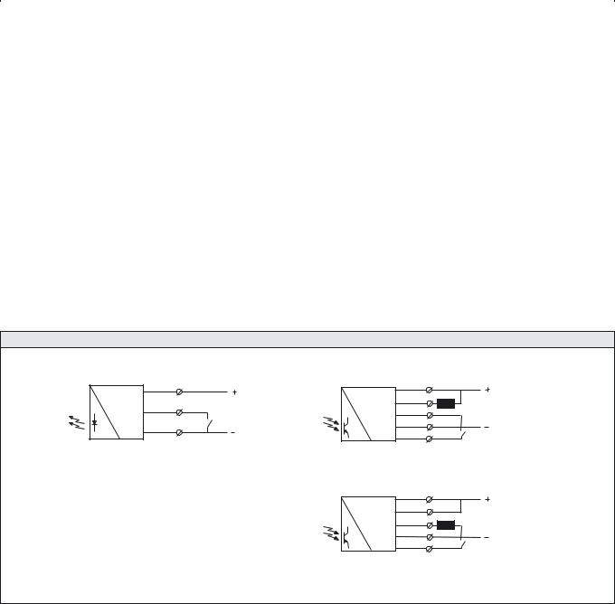
SG 10 |
|
|
|
|
|
|
|
|
SPACEGUARD™ SERIES |
|||
|
|
|
|
|
|
|
|
|
|
|
|
|
Environmental Data |
|
|
|
|
|
|
|
|
||||
Light immunity @ 5° incidence |
|
|
|
|
|
|
|
> 100 000 lux |
||||
|
|
|
|
|
|
|
|
|
|
|
|
|
Temperature, operation |
|
|
|
|
|
|
|
–20 to +65 °C |
||||
|
|
|
|
|
|
|
|
|
|
|
|
|
Temperature, storage |
|
|
|
|
|
|
|
–40 to +80 °C |
||||
|
|
|
|
|
|
|
|
|
|
|
|
|
Sealing class |
|
|
|
|
|
|
|
|
IP 67 |
|||
|
|
|
|
|
|
|
|
|
|
|
|
|
Approvals |
|
|
|
|
|
|
|
|
a |
|||
|
|
|
|
|
|
|
|
|
|
|
|
|
|
|
|
|
|
|
|
|
|
|
|
|
|
Available Types |
|
|
|
|
|
|
|
|
|
|||
|
Housing |
|
|
Active |
Number of |
Number of |
|
Beam |
Housing Design |
Slim Line |
||
|
Length |
|
Height |
Channels |
Beams |
Spacing |
|
Output |
Order reference |
|||
Detector |
|
|
|
|
|
|
|
|
|
|
|
|
850 mm |
|
|
650 mm |
8 |
34 |
|
92 mm |
|
|
|
SGT 10-085-008-B1-C-00-5 |
|
|
|
|
|
|
|
|
||||||
|
|
|
|
|
|
|
|
|
|
|
|
|
|
|
|
695 mm |
16 |
74 |
|
46 mm |
|
|
|
SGT 10-085-016-A1-C-00-5 |
|
|
|
|
|
|
|
|
|
|||||
|
|
|
|
|
|
|
|
|
|
|
|
|
Transmitter |
1250 mm |
|
|
1020 mm |
12 |
54 |
|
92 mm |
|
|
|
SGT 10-125-012-B1-C-00-5 |
|
|
|
|
|
|
|
|
|
|
|
||
|
|
1065 mm |
24 |
114 |
|
46 mm |
– |
|
– |
SGT 10-125-024-A1-C-00-5 |
||
|
|
|
|
|
||||||||
|
|
|
|
|
|
|||||||
|
|
|
|
|
|
|
|
|
|
|
||
|
1600 mm |
|
|
1385 mm |
16 |
74 |
|
92 mm |
|
SGT 10-160-016-B1-C-00-5 |
||
|
|
|
|
|
|
|
||||||
|
|
|
|
|
|
|
|
|
|
|
|
|
|
|
|
1430 mm |
32 |
154 |
|
46 mm |
|
|
|
SGT 10-160-032-A1-C-00-5 |
|
|
|
|
|
|
|
|
|
|||||
|
|
|
|
|
|
|
|
|
|
|
|
|
|
2000 mm |
|
|
1755 mm |
20 |
94 |
|
92 mm |
|
|
|
SGT 10-200-020-B1-C-00-5 |
|
|
|
|
|
|
|
|
|
|
|
|
|
|
|
|
1800 mm |
40 |
194 |
|
46 mm |
|
|
|
SGT 10-200-040-A1-C-00-5 |
|
|
|
|
|
|
|
|
|
|||||
|
|
|
|
|
|
|
|
|
|
|
|
|
|
|
|
|
|
|
|
|
|
|
|
|
|
|
850 mm |
|
|
650 mm |
8 |
34 |
|
92 mm |
|
|
|
SGR 10-085-008-B1-C-07-5 |
|
|
|
|
|
|
|
|
|
|
|
|
|
Detector |
|
|
695 mm |
16 |
74 |
|
46 mm |
|
|
|
SGR 10-085-016-A1-C-07-5 |
|
|
|
|
|
|
|
|
||||||
|
|
|
|
|
|
|
|
|
|
|
|
|
1250 mm |
|
|
1020 mm |
12 |
54 |
|
92 mm |
|
|
|
SGR 10-125-012-B1-C-07-5 |
|
|
|
|
|
|
|
|
||||||
|
|
|
|
|
|
|
|
|
|
|
|
|
|
|
|
1065 mm |
24 |
114 |
|
46 mm |
Solid State |
NO/NC |
SGR 10-125-024-A1-C-07-5 |
||
|
|
|
|
|
||||||||
|
|
|
|
|
|
|
|
|
|
|||
Receiver |
|
|
|
1385 mm |
16 |
74 |
|
92 mm |
Relay |
|
SGR 10-160-016-B1-C-07-5 |
|
|
|
|
|
|
|
|||||||
|
|
|
|
|
|
|
||||||
|
1600 mm |
|
|
|
|
|
|
|||||
|
|
|
|
|
|
|
|
|
|
|
|
|
|
|
|
1430 mm |
32 |
154 |
|
46 mm |
|
|
|
SGR 10-160-032-A1-C-07-5 |
|
|
|
|
|
|
|
|
|
|||||
|
|
|
|
|
|
|
|
|
|
|
|
|
|
2000 mm |
|
|
1755 mm |
20 |
94 |
|
92 mm |
|
|
|
SGR 10-200-020-B1-C-07-5 |
|
|
|
|
|
|
|
|
|
|
|
|
|
|
|
|
1800 mm |
40 |
194 |
|
46 mm |
|
|
|
SGR 10-200-040-A1-C-07-5 |
|
|
|
|
|
|
|
|
|
|||||
|
|
|
|
|
|
|
|
|
|
|
|
|
Note: The transmitter SGT and receiver SGR set must have the same number of channels and same beam spacing.
Wiring Diagrams
Brown |
Black |
ON/OFF |
Switch |
Blue |
SGT 10
Brown
Black Load
Black
Blue
White
Light/Dark
SGR 10 (load as NPN)
Brown |
|
Black |
|
Black |
Load |
|
|
Blue |
|
White |
Light/Dark |
|
SGR 10 (load as PNP)
112 I SELF-CONTAINED LIGHT CURTAIN SYSTEMS
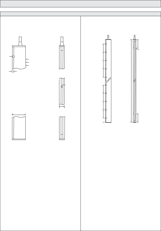
SPACEGUARD™ SERIES
Dimensions and Descriptions
|
Details |
|
|
Top Side View |
Top Rear View |
|
Cable |
Cable |
Rear |
Front |
200 |
Ø 4 |
|
200 |
|
System status indicator (SGR) |
|
|
Output indicator (SGR) |
200 |
|
Power on indicator (SGT/SGR) |
|
|
|
|
|
3,5 |
200 |
|
|
|
|
|
Mounting |
|
|
Slot 4,4 |
200
200
200
12
30 |
200 |
100 
SGT/SGR
Side View
Rear |
Front |
Bottom Side View |
Bottom Rear View |
SG 10
200
Ø 8
Length (refer to Available Types)
200
SGT/SGR
Rear View
(Units in mm)
SELF-CONTAINED LIGHT CURTAIN SYSTEMS I 113
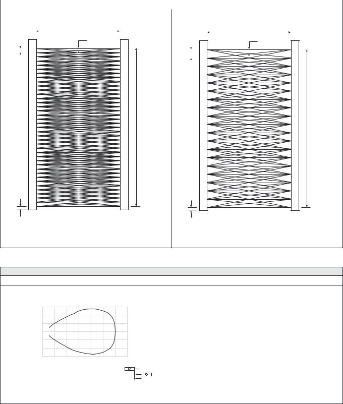
SG 10 |
|
|
|
|
|
|
|
|
|
|
|
SPACEGUARD™ SERIES |
|
||||||||||
|
|
|
|
|
|
|
|
|
|
|
|
|
|
|
|
|
|
|
|
|
|
|
|
Beam Patterns |
|
|
|
|
|
|
|
|
|
|
|
|
|
|
|
|
|
|
|||||
|
|
|
|
|
|
1 000 – 10 000 |
|
|
|
|
|
|
|
1 000 – 10 000 |
|
|
|
||||||
|
|
|
|
|
|
|
|
|
|
|
|
|
|
||||||||||
|
|
|
|
|
|
|
|
|
|
|
|
|
|
|
|
|
|
|
|
|
|
|
|
|
|
|
|
|
|
|
|
|
|
|
|
|
|
|
|
|
|
|
|
|
|
|
|
46 |
|
|
|
|
|
Pinch point: 23 |
92 |
|
|
|
|
Pinch point: 46 |
|
||||||||||
|
|
|
|
|
|
|
|
|
|
|
|
|
|||||||||||
|
|
|
|
|
|
|
|
|
|
|
|
|
|
|
|
|
|
|
|
|
|
|
|
|
|
|
|
|
|
|
|
|
|
|
|
|
|
|
|
|
|
|
|
|
|
|
|
|
|
|
|
|
|
|
|
|
|
|
|
|
|
|
|
|
|
|
|
|
|
|
|
|
|
|
|
|
|
|
|
|
|
|
|
|
|
|
|
|
|
|
|
|
|
|
|
|
|
|
|
|
|
|
|
|
|
|
|
|
|
|
|
|
|
|
|
|
|
|
|
Active Height (refer to Available Types) |
Active Height (refer to Available Types) |
25 |
25 |
46 mm beam spacing |
92 mm beam spacing |
(Units in mm)
Sensing Characteristics
Parallel Displacement
Displacement (cm)
120
80
40
0
–40
–80
–120
0 |
2 |
4 |
6 |
8 |
10 |
12 |
14 |
Range (m)
 Y
Y
Slim Line |
X |
Telco reserves the right to change specifications without notice.
114 I SELF-CONTAINED LIGHT CURTAIN SYSTEMS
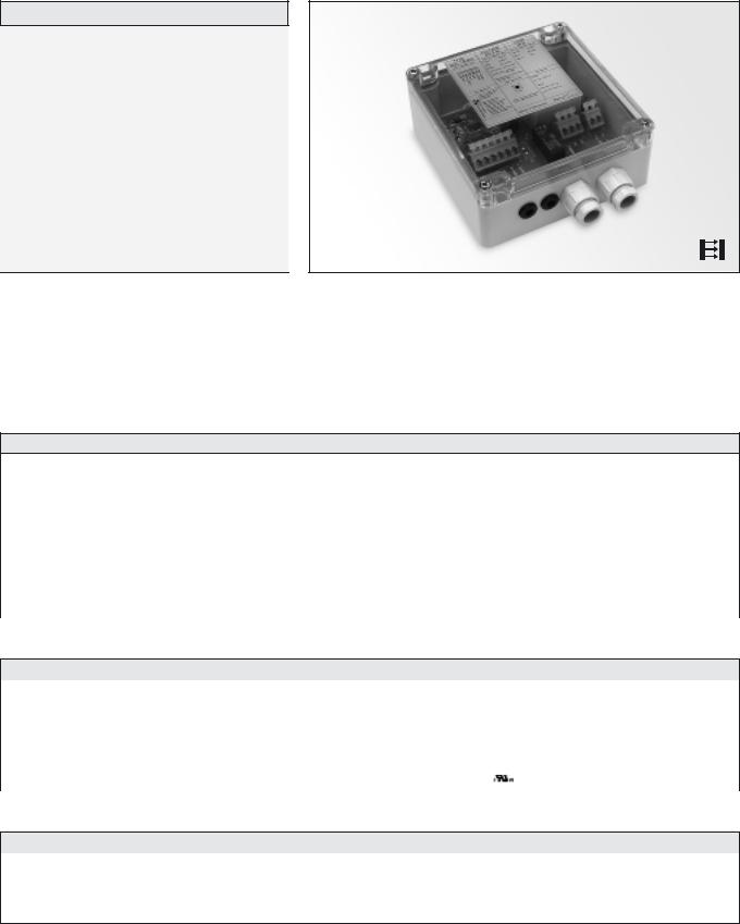
SPACEGUARD™ SERIES |
SGC 1 |
Description
115 V ac or 230 V ac supply voltage
Relay output
Switch selectable light or dark function
Switch selectable receiver control function
Test push button
Power and output indicators
Spring-clamp terminal connection
The SGC |
1 is intended to be used in conjunction with the SG 1, SG 2 |
|
|
|
The SGC 1 offers a test button, which may be used for disabling or |
||||
or SG 10 |
self-contained light curtain series, where a DC supply voltage |
enabling the transmitting power temporarily for test purposes. |
||
is not available and where a relay output is required. This controller series |
|
|
|
|
is supplied with a fixed 24 V dc output voltage. Light or dark function and |
|
|
|
|
receiver control function is switch selectable.
Technical Data
Supply voltage |
115 V ac or 230 V ac |
|
|
Voltage tolerance |
+/– 10% |
|
|
Current consumption |
Max. 7 VA |
|
|
Relay output |
1 open / 1 close, 250 V ac / 3A, 120 V ac / 5A |
|
|
Supply output voltage |
24 V dc |
|
|
Supply output current |
150 mA |
|
|
Power on indicator |
Green LED |
|
|
Output indicator |
Yellow LED |
|
|
Housing material |
ABS |
|
|
Environmental Data
Vibration |
10 – 55 Hz, 1,5 mm |
|
|
Shock |
30 g |
|
|
Temperature, operation |
–20 to +65 ºC |
|
|
Temperature, storage |
–40 to +80 ºC |
|
|
Sealing class |
IP 41 |
|
|
Approvals |
a |
|
|
Available Types
Model |
Connection |
Supply Voltage |
115 V ac |
|
230 V ac |
|
|
|
|
||
Output |
|
Order Reference |
|||
|
|
|
|||
|
|
|
|
|
|
SGC 1 B |
Spring-clamp terminals |
Relay |
SGC 1 B 501 |
|
SGC 1 B 500 |
|
|
|
|
|
|
SELF-CONTAINED LIGHT CURTAIN SYSTEMS I 115
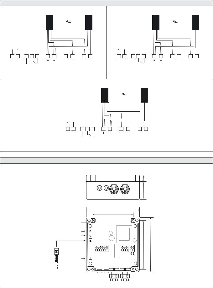
SGC 1 |
SPACEGUARD™ SERIES |
Wiring Diagrams |
|
|
|
|
|
|
|
|
|
|
|
|
|
|
|
|
|
|
|
|
|
SGR |
|
|
|
SGT |
|
|
|
|
|
|
SGR |
|
|
|
SGT |
|
|
|
Brown |
|
|
|
|
Black |
|
|
|
|
|
Brown |
|
|
|
Black |
|
|
|
|
White |
|
|
|
|
|
|
|
|
|
|
White |
|
|
|
|
|
|
|
Black |
|
|
|
|
|
|
|
|
|
Black |
|
|
|
|
|
|
|
Blue |
Brown |
|
|
|
|
|
|
|
|
|
Blue |
|
Brown |
|
|
|
|
|
|
|
|
|
|
|
|
|
|
|
|
|
|
|
||
ac-supply |
Relay output |
|
|
|
|
|
|
ac-supply |
|
Relay output |
|
|
|
|
||||
|
|
|
|
|
|
Blue |
|
|
|
|
|
|
|
|
|
|
Blue |
|
|
NO |
NC |
C |
|
|
|
|
|
|
|
|
NO |
NC |
C |
|
|
|
|
|
|
|
|
NPN |
PNP |
RX |
Test |
|
|
|
|
|
|
NPN |
PNP |
RX |
Test |
|
|
|
|
dc-output |
input |
input |
control |
|
|
|
|
|
|
dc-output |
input |
input |
control |
||
|
|
|
Light curtains with PNP output |
|
|
|
|
|
|
|
|
Light curtains with NPN output |
|
|
||||
|
|
|
|
|
|
|
|
SGR |
|
|
|
|
|
SGT |
|
|
|
|
|
|
|
|
|
|
|
|
Brown |
|
|
|
|
|
Black |
|
|
|
|
|
|
|
|
|
|
|
|
|
|
White |
|
|
|
|
|
|
|
|
|
|
|
|
|
|
|
|
|
|
Black |
|
|
|
|
|
|
|
|
|
|
|
|
|
|
|
|
Blue |
Black |
Brown |
|
|
|
|
|
|
|
|
|
|
|
|
|
|
|
|
|
|
|
|
|
|
|
|
|
||
|
|
|
|
ac-supply |
Relay output |
|
|
|
|
|
|
|
|
|
|
|||
|
|
|
|
|
|
|
|
|
|
|
|
Blue |
|
|
|
|
|
|
|
|
|
|
|
|
NO |
NC |
C |
|
|
|
|
|
|
|
|
|
|
|
|
|
|
|
|
|
|
|
|
NPN |
PNP |
|
RX |
Test |
|
|
|
|
|
|
|
|
|
|
|
|
dc-output |
input |
input |
|
control |
|
|
|
|
||
|
|
|
|
|
|
Light curtains with opto isolated NPN/PNP output |
|
|
|
|
|
|
||||||
Dimensions and Descriptions
Ø 4mm
Power on indicator
Output indicator
Output standard |
Test button |
|
Output inverted |
||
|
||
RX control on |
|
|
RX control off |
|
|
|
|
|
|
|
|
|
|
|
|
16 |
|
|
|
|
|
|
|
|
|
|
|
|
40 |
|
|
|
|
|
|
|
|
120 |
|
|
|
|
|
|
|
|
|
|
|
|
90 |
|
|
|
|
|
|
POWER |
|
|
|
|
|
|
|
|
|
|
|
|
OUTPUT |
|
|
|
|
|
|
|
|
|
|
|
ON |
|
|
|
|
|
|
|
|
|
|
|
|
1 2 |
TEST |
CONTROLRX |
PNP |
NPN |
GND0V– |
SUPPLY+ |
COMMON |
NC |
NO |
SUPPLY |
AC |
|
CONTROLRX OUTPUTINVERT |
122 |
|||||||||||
|
|
|
|
|
|
|
|
|
|
|
110 |
TEST
(Units in mm)
Telco reserves the right to change specifications without notice.
116 I SELF-CONTAINED LIGHT CURTAIN SYSTEMS
SPACEGUARD™ SERIES |
SG 11 |
Description
5 m sensing range
16 to 64 parallel beams
28 or 56 mm beam spacing
Active height of 425 mm to 1770 mm
Detector length of 570 mm to 2105 mm
Flexible or non-flexible cable with plug connection
Slim line (10 x 28 mm) or leading edge (37,5 x 13 mm) detector housing
The SpaceGuard SG 11 light curtain series, which consists of a transmitter detector, SGT and receiver detector, SGR, is made to operate in conjunction with a controller SGC 11. The detectors are housed in an aluminium profile available in a slim line design (10 x 28 mm) and a leading edge design (37,5 x 13 mm). The system can be used both in static and dynamic installations.
Technical Data
|
28 mm channel spacing |
|
56 mm channel spacing |
|
|||
|
|
|
|
|
|
|
|
|
SGT |
|
SGR |
SGT |
|
SGR |
|
|
|
|
|
|
|
|
|
Light source |
Infrared (940 nm) |
|
– |
Infrared (940 nm) |
|
– |
|
|
|
|
|
|
|
|
|
Number of channels (diodes per detector) |
16, 24, 32, 48, 56 or 64 |
|
16, 24 or 32 |
|
|||
|
|
|
|
|
|
|
|
Number of parallel beams |
16, 24, 32, 48, 56 or 64 |
|
16, 24 or 32 |
|
|||
|
|
|
|
|
|
||
Active height |
425, 650, 875, 1100, 1320, 1545 or 1770 mm |
845, 1295 or 1740 mm |
|
||||
|
|
|
|
|
|||
Channel spacing |
Between channel 1 and bottom of housing: 22 mm |
Between channel 1 and bottom of housing: 22 mm |
|||||
Between other channels: 28 mm |
Between other channels: 56 mm |
||||||
|
|||||||
|
|
|
|
|
|
|
|
Slim Line |
|
|
10 x 28 mm |
|
|||
Housing dimensions |
|
|
|
|
|
|
|
|
|
|
|
|
|
||
Leading Edge |
|
|
37,5 x 13 mm |
|
|||
|
|
|
|
|
|
|
|
Housing material |
|
|
Aluminium |
|
|||
|
|
|
|
|
|
|
|
Housing colour |
|
|
Black anodized |
|
|||
|
|
|
|
|
|
|
|
Front cover |
|
|
Infrared transparent plastic |
|
|||
|
|
|
|
|
|
|
|
Environmental Data
Light immunity @ 20° incidence |
> 10 000 lux |
|
|
Temperature, operation |
–20 to +55 ºC |
|
|
Temperature, storage |
–40 to +80 ºC |
|
|
Sealing class |
IP 55 |
|
|
Approvals |
a |
|
|
REMOTE LIGHT CURTAIN SYSTEMS I 117
SG 11 |
|
|
|
|
|
SPACEGUARD™ SERIES |
|||
|
|
|
|
|
|
|
|
|
|
Available Types |
|
|
|
|
|
|
|||
Slim Line Housing |
|
|
|
|
|
|
|||
|
|
|
|
|
|
|
|
|
|
|
Housing |
Active |
Connection |
4 m flexible cable |
4 m non-flexible cable |
0.5 m flexible cable |
0.5 m non-flexible cable |
||
|
|
|
|
|
|
|
|||
|
No of |
Beam |
|
|
|
|
|||
|
Length |
Height |
|
Order Reference |
|
||||
|
Beams |
Space |
|
|
|||||
|
|
|
|
|
|
|
|||
|
|
|
|
|
|
|
|
|
|
|
570 mm |
425 mm |
16 |
28 mm |
SGT 057-016-A1-A-4F |
SGT 057-016-A1-A-4 |
SGT 057-016-A1-A-0.5F |
SGT 057-016-A1-A-0.5 |
|
Detector |
795 mm |
650 mm |
24 |
SGT 080-024-A1-A-4F |
SGT 080-024-A1-A-4 |
SGT 080-024-A1-A-0.5F |
SGT 080-024-A1-A-0.5 |
||
|
|||||||||
|
|
|
|
|
|
|
|
||
|
845 mm |
16 |
28 mm |
SGT 102-016-B1-A-4F |
SGT 102-016-B1-A-4 |
SGT 102-016-B1-A-0.5F |
SGT 102-016-B1-A-0.5 |
||
|
1020 mm |
875 mm |
32 |
|
SGT 102-032-A1-A-4F |
SGT 102-032-A1-A-4 |
SGT 102-032-A1-A-0.5F |
SGT 102-032-A1-A-0.5 |
|
|
|
|
|||||||
Transmitter |
1245 mm |
1100 mm |
40 |
|
SGT 125-040-A1-A-4F |
SGT 125-040-A1-A-4 |
SGT 125-040-A1-A-0.5F |
SGT 125-040-A1-A-0.5 |
|
|
|
|
|
|
|
|
|
||
1695 mm |
1545 mm |
56 |
56 mm |
SGT 170-056-A1-A-4F |
SGT 170-056-A1-A-4 |
SGT 170-056-A1-A-0.5F |
SGT 170-056-A1-A-0.5 |
||
|
1470 mm |
1295 mm |
24 |
SGT 147-024-B1-A-4F |
SGT 147-024-B1-A-4 |
SGT 147-024-B1-A-0.5F |
SGT 147-024-B1-A-0.5 |
||
|
1320 mm |
48 |
28 mm |
SGT 147-048-A1-A-4F |
SGT 147-048-A1-A-4 |
SGT 147-048-A1-A-0.5F |
SGT 147-048-A1-A-0.5 |
||
|
|
||||||||
|
|
|
|
|
|
|
|
||
|
|
|
|
|
|
|
|
|
|
|
1995 mm |
1740 mm |
32 |
56 mm |
SGT 200-032-B1-A-4F |
SGT 200-032-B1-A-4 |
SGT 200-032-B1-A-0.5F |
SGT 200-032-B1-A-0.5 |
|
|
|
|
|
|
|
|
|
||
|
1770 mm |
64 |
28 mm |
SGT 200-064-A1-A-4F |
SGT 200-064-A1-A-4 |
SGT 200-064-A1-A-0.5F |
SGT 200-064-A1-A-0.5 |
||
|
|
||||||||
|
|
|
|
|
|
|
|
|
|
|
2105 mm |
1740 mm |
32 |
56 mm |
SGT 210-032-B1-A-4F |
SGT 210-032-B1-A-4 |
SGT 210-032-B1-A-0.5F |
SGT 210-032-B1-A-0.5 |
|
|
|
|
|
|
|
|
|
||
|
1770 mm |
64 |
28 mm |
SGT 210-064-A1-A-4F |
SGT 210-064-A1-A-4 |
SGT 210-064-A1-A-0.5F |
SGT 210-064-A1-A-0.5 |
||
|
|
||||||||
|
|
|
|
|
|
|
|
|
|
|
|
|
|
|
|
|
|
|
|
|
570 mm |
425 mm |
16 |
28 mm |
SGR 057-016-A1-A-4F |
SGR 057-016-A1-A-4 |
SGR 057-016-A1-A-0.5F |
SGR 057-016-A1-A-0.5 |
|
|
|
|
|
|
|
|
|
||
|
795 mm |
650 mm |
24 |
SGR 080-024-A1-A-4F |
SGR 080-024-A1-A-4 |
SGR 080-024-A1-A-0.5F |
SGR 080-024-A1-A-0.5 |
||
|
|
||||||||
|
|
|
|
|
|
|
|
|
|
|
1020 mm |
845 mm |
16 |
56 mm |
SGR 102-016-B1-A-4F |
SGR 102-016-B1-A-4 |
SGR 102-016-B1-A-0.5F |
SGR 102-016-B1-A-0.5 |
|
|
|
|
|
|
|
|
|
||
Detector |
875 mm |
32 |
28 mm |
SGR 102-032-A1-A-4F |
SGR 102-032-A1-A-4 |
SGR 102-032-A1-A-0.5F |
SGR 102-032-A1-A-0.5 |
||
|
|||||||||
|
|
|
|
|
|
|
|||
|
1245 mm |
1100 mm |
40 |
SGR 125-040-A1-A-4F |
SGR 125-040-A1-A-4 |
SGR 125-040-A1-A-0.5F |
SGR 125-040-A1-A-0.5 |
||
|
|
||||||||
|
|
|
|
|
|
|
|
|
|
|
1470 mm |
1295 mm |
24 |
56 mm |
SGR 147-024-B1-A-4F |
SGR 147-024-B1-A-4 |
SGR 147-024-B1-A-0.5F |
SGR 147-024-B1-A-0.5 |
|
Receiver |
|
|
|
|
|
|
|
||
1320 mm |
48 |
28 mm |
SGR 147-048-A1-A-4F |
SGR 147-048-A1-A-4 |
SGR 147-048-A1-A-0.5F |
SGR 147-048-A1-A-0.5 |
|||
|
|||||||||
|
|
|
|
|
|
|
|
||
|
1695 mm |
1545 mm |
56 |
SGR 170-056-A1-A-4F |
SGR 170-056-A1-A-4 |
SGR 170-056-A1-A-0.5F |
SGR 170-056-A1-A-0.5 |
||
|
|
||||||||
|
|
|
|
|
|
|
|
|
|
|
1995 mm |
1740 mm |
32 |
56 mm |
SGR 200-032-B1-A-4F |
SGR 200-032-B1-A-4 |
SGR 200-032-B1-A-0.5F |
SGR 200-032-B1-A-0.5 |
|
|
|
|
|
|
|
|
|
||
|
1770 mm |
64 |
28 mm |
SGR 200-064-A1-A-4F |
SGR 200-064-A1-A-4 |
SGR 200-064-A1-A-0.5F |
SGR 200-064-A1-A-0.5 |
||
|
|
||||||||
|
|
|
|
|
|
|
|
|
|
|
2105 mm |
1740 mm |
32 |
56 mm |
SGR 210-032-B1-A-4F |
SGR 210-032-B1-A-4 |
SGR 210-032-B1-A-0.5F |
SGR 210-032-B1-A-0.5 |
|
|
|
|
|
|
|
|
|
||
|
1770 mm |
64 |
28 mm |
SGR 210-064-A1-A-4F |
SGR 210-064-A1-A-4 |
SGR 210-064-A1-A-0.5F |
SGR 210-064-A1-A-0.5 |
||
|
|
||||||||
|
|
|
|
|
|
|
|
|
|
|
|
|
|
|
|
|
|
||
Leading Edge Housing |
|
|
|
|
|
|
|||
|
570 mm |
425 mm |
16 |
28 mm |
SGT 057-016-A1-B-4F |
SGT 057-016-A1-B-4 |
SGT 057-016-A1-B-0.5F |
SGT 057-016-A1-B-0.5 |
|
|
|
|
|
|
|
|
|
||
|
795 mm |
650 mm |
24 |
SGT 080-024-A1-B-4F |
SGT 080-024-A1-B-4 |
SGT 080-024-A1-B-0.5F |
SGT 080-024-A1-B-0.5 |
||
|
|
||||||||
|
|
|
|
|
|
|
|
|
|
Detector |
1020 mm |
845 mm |
16 |
56 mm |
SGT 102-016-B1-B-4F |
SGT 102-016-B1-B-4 |
SGT 102-016-B1-B-0.5F |
SGT 102-016-B1-B-0.5 |
|
|
|
|
|
|
|
|
|||
875 mm |
32 |
28 mm |
SGT 102-032-A1-B-4F |
SGT 102-032-A1-B-4 |
SGT 102-032-A1-B-0.5F |
SGT 102-032-A1-B-0.5 |
|||
|
|||||||||
|
|
||||||||
|
|
|
|
|
|
|
|
||
|
1245 mm |
1100 mm |
40 |
SGT 125-040-A1-B-4F |
SGT 125-040-A1-B-4 |
SGT 125-040-A1-B-0.5F |
SGT 125-040-A1-B-0.5 |
||
|
|
||||||||
|
|
|
|
|
|
|
|
|
|
Transmitter |
1995 mm |
1295 mm |
24 |
56 mm |
SGT 147-024-B1-B-4F |
SGT 147-024-B1-B-4 |
SGT 147-024-B1-B-0.5F |
SGT 147-024-B1-B-0.5 |
|
|
1470 mm |
|
|
|
|
|
|
|
|
|
1320 mm |
48 |
28 mm |
SGT 147-048-A1-B-4F |
SGT 147-048-A1-B-4 |
SGT 147-048-A1-B-0.5F |
SGT 147-048-A1-B-0.5 |
||
|
|
||||||||
|
|
|
|
|
|
|
|
||
|
1695 mm |
1545 mm |
56 |
SGT 170-056-A1-B-4F |
SGT 170-056-A1-B-4 |
SGT 170-056-A1-B-0.5F |
SGT 170-056-A1-B-0.5 |
||
|
|
||||||||
|
|
|
|
|
|
|
|
|
|
|
|
1740 mm |
32 |
56 mm |
SGT 200-032-B1-B-4F |
SGT 200-032-B1-B-4 |
SGT 200-032-B1-B-0.5F |
SGT 200-032-B1-B-0.5 |
|
|
|
|
|
|
|
|
|
|
|
|
|
1770 mm |
64 |
28 mm |
SGT 200-064-A1-B-4F |
SGT 200-064-A1-B-4 |
SGT 200-064-A1-B-0.5F |
SGT 200-064-A1-B-0.5 |
|
|
|
|
|
|
|
|
|
|
|
|
2105 mm |
1740 mm |
32 |
56 mm |
SGT 210-032-B1-B-4F |
SGT 210-032-B1-B-4 |
SGT 210-032-B1-B-0.5F |
SGT 210-032-B1-B-0.5 |
|
|
|
|
|
|
|
|
|
||
|
1770 mm |
64 |
28 mm |
SGT 210-064-A1-B-4F |
SGT 210-064-A1-B-4 |
SGT 210-064-A1-B-0.5F |
SGT 210-064-A1-B-0.5 |
||
|
|
||||||||
|
|
|
|
|
|
|
|
|
|
|
|
|
|
|
|
|
|
|
|
|
570 mm |
425 mm |
16 |
28 mm |
SGR 057-016-A1-B-4F |
SGR 057-016-A1-B-4 |
SGR 057-016-A1-B-0.5F |
SGR 057-016-A1-B-0.5 |
|
|
|
|
|
|
|
|
|
||
|
795 mm |
650 mm |
24 |
SGR 080-024-A1-B-4F |
SGR 080-024-A1-B-4 |
SGR 080-024-A1-B-0.5F |
SGR 080-024-A1-B-0.5 |
||
|
|
||||||||
|
|
|
|
|
|
|
|
|
|
|
1020 mm |
845 mm |
16 |
56 mm |
SGR 102-016-B1-B-4F |
SGR 102-016-B1-B-4 |
SGR 102-016-B1-B-0.5F |
SGR 102-016-B1-B-0.5 |
|
Detector |
|
|
|
|
|
|
|
||
875 mm |
32 |
28 mm |
SGR 102-032-A1-B-4F |
SGR 102-032-A1-B-4 |
SGR 102-032-A1-B-0.5F |
SGR 102-032-A1-B-0.5 |
|||
|
|||||||||
|
1245 mm |
1100 mm |
40 |
SGR 125-040-A1-B-4F |
SGR 125-040-A1-B-4 |
SGR 125-040-A1-B-0.5F |
SGR 125-040-A1-B-0.5 |
||
|
|
||||||||
|
|
|
|
|
|
|
|
|
|
|
1470 mm |
1295 mm |
24 |
56 mm |
SGR 147-024-B1-B-4F |
SGR 147-024-B1-B-4 |
SGR 147-024-B1-B-0.5F |
SGR 147-024-B1-B-0.5 |
|
Receiver |
|
|
|
|
|
|
|
||
1740 mm |
32 |
56 mm |
SGR 200-032-B1-B-4F |
SGR 200-032-B1-B-4 |
SGR 200-032-B1-B-0.5F |
SGR 200-032-B1-B-0.5 |
|||
|
|
1320 mm |
48 |
28 mm |
SGR 147-048-A1-B-4F |
SGR 147-048-A1-B-4 |
SGR 147-048-A1-B-0.5F |
SGR 147-048-A1-B-0.5 |
|
|
1695 mm |
1545 mm |
56 |
SGR 170-056-A1-B-4F |
SGR 170-056-A1-B-4 |
SGR 170-056-A1-B-0.5F |
SGR 170-056-A1-B-0.5 |
||
|
|
||||||||
|
1995 mm |
|
|
|
|
|
|
|
|
|
1770 mm |
64 |
28 mm |
SGR 200-064-A1-B-4F |
SGR 200-064-A1-B-4 |
SGR 200-064-A1-B-0.5F |
SGR 200-064-A1-B-0.5 |
||
|
|
||||||||
|
|
|
|
|
|
|
|
|
|
|
2105 mm |
1740 mm |
32 |
56 mm |
SGR 210-032-B1-B-4F |
SGR 210-032-B1-B-4 |
SGR 210-032-B1-B-0.5F |
SGR 210-032-B1-B-0.5 |
|
|
|
|
|
|
|
|
|
||
|
1770 mm |
64 |
28 mm |
SGR 210-064-A1-B-4F |
SGR 210-064-A1-B-4 |
SGR 210-064-A1-B-0.5F |
SGR 210-064-A1-B-0.5 |
||
|
|
||||||||
|
|
|
|
|
|
|
|
|
|
Note: 1. The transmitter SGT and the receiver SGR set must always have the same number of light beams and the same beam spacing 2. Special lengths are available upon request
118 I REMOTE LIGHT CURTAIN SYSTEMS
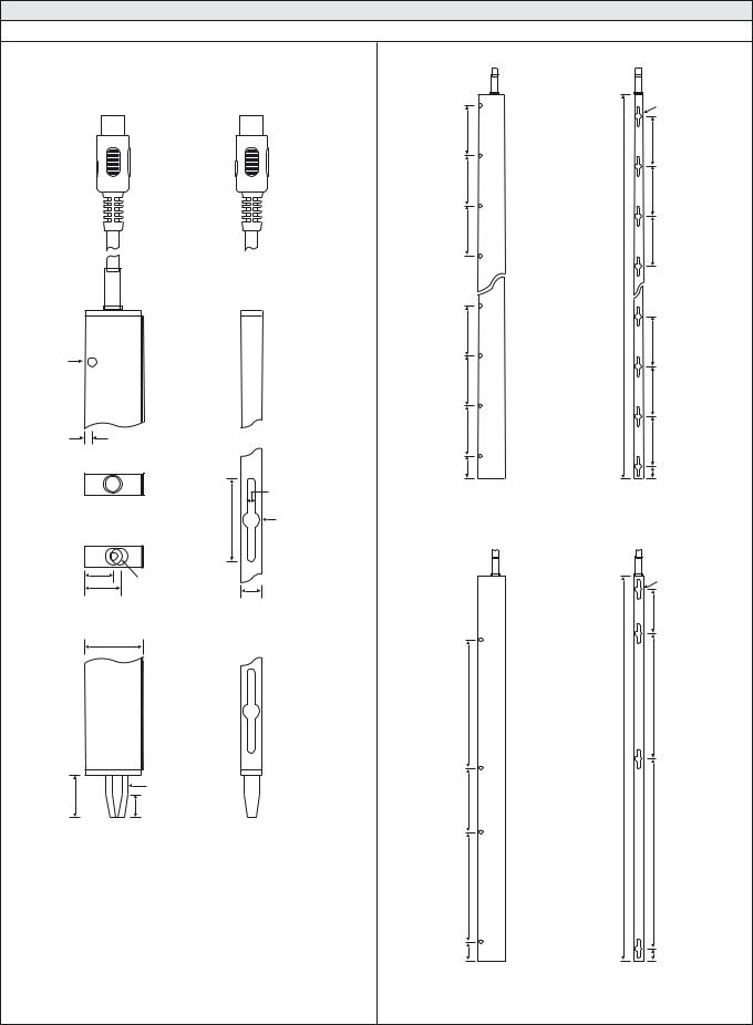
SPACEGUARD™ SERIES |
SG 11 |
Dimensions and Descriptions
Slim Line
Details
Top Side View
|
Cable |
Rear |
Front |
Ø 4,4 |
|
Top Rear View
225
225
225
Cable
225
225
Length (refer to Available Types)
Ø 8
225
225
225
225
225
3,25 |
|
|
|
Top View |
|
|
|
|
|
|
Mounting |
|
|
|
Slot 4,4 |
|
|
40 |
Ø 8 |
Bottom View |
|
|
|
14 |
Ø 8 |
|
|
17,5 |
|
|
|
Bottom Side View |
Bottom Rear View |
||
28 |
|
|
|
Rear |
Front |
|
20 |
Ø 8 |
Positioning Pin |
10 |
(removable) |
|
|
|
225
225
100
50
SGT/SGR |
SGT/SGR |
Side View |
Rear View |
057 to 200
Ø 8
250
700
700
350
1050
600
102 |
50 |
|
SGT/SGR |
SGT/SGR |
Side View |
Rear View |
210 (only)
(Units in mm)
REMOTE LIGHT CURTAIN SYSTEMS I 119
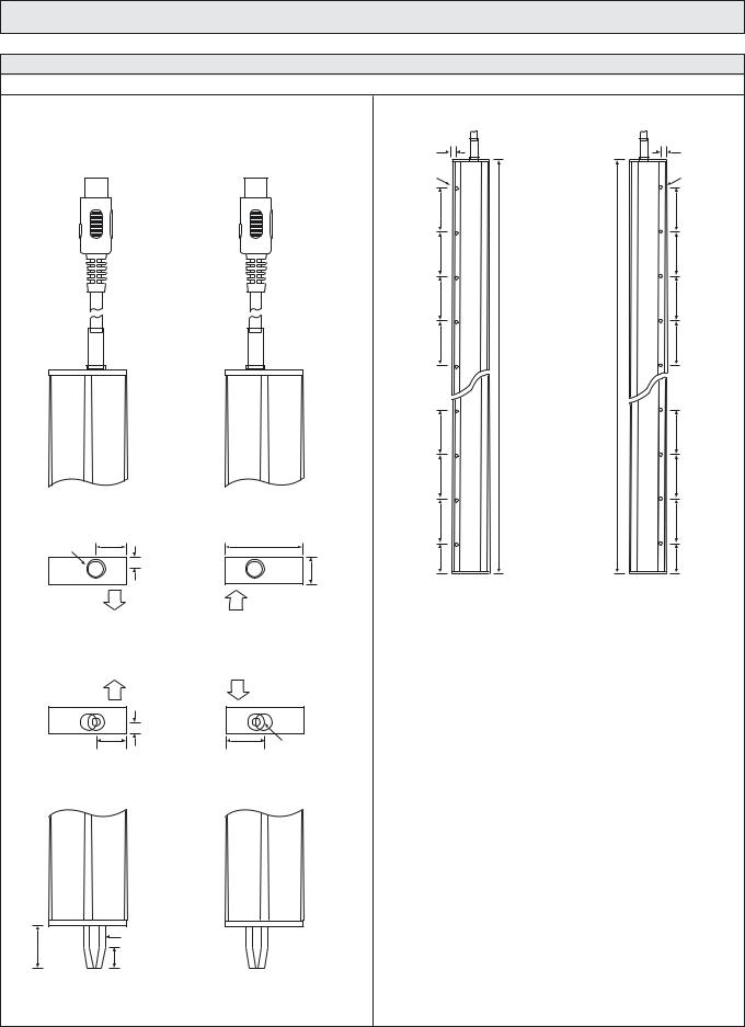
SG 11
Dimensions and Descriptions
Leading Edge
Details
SGT
Top Front View
Cable
SGR
Top Front View
Cable
Top View |
Top View |
|
14,5 |
|
37,5 |
Ø 9 |
|
|
|
|
13 |
Transmitting |
|
Receiving |
direction |
|
direction |
|
Bottom View |
|
Transmitting |
|
Receiving |
direction |
|
direction |
14,5 |
18 |
Ø 8 |
Bottom Front View |
Bottom Front View |
|
|
Ø 8 |
Positioning Pin |
20 |
|
|
|
(removable) |
|
|
10 |
|
|
|
SPACEGUARD™ SERIES
6 |
|
|
6 |
Ø 3 |
|
|
Ø 3 |
225 |
|
|
225 |
225 |
|
|
225 |
225 |
Types) |
Types) |
225 |
|
|
||
225 |
Availableto(referLength |
Availableto(referLength |
225 |
|
|
||
225 |
|
|
225 |
225 |
|
|
225 |
225 |
|
|
225 |
152,5 |
|
|
152,5 |
SGR |
SGT |
Rear View |
Rear View |
|
057 to 210 |
(Units in mm)
120 I REMOTE LIGHT CURTAIN SYSTEMS
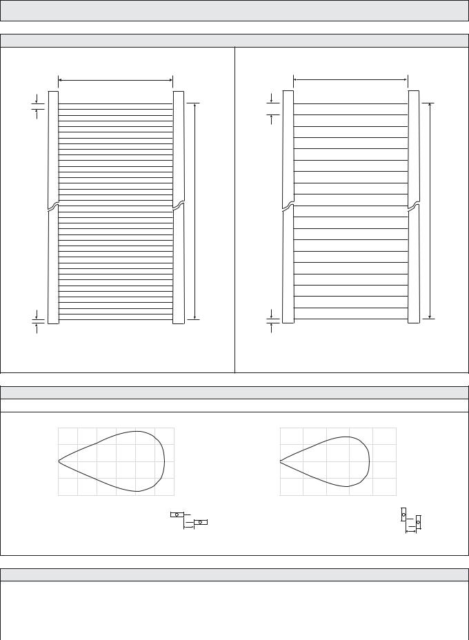
SPACEGUARD™ SERIES |
SG 11 |
Beam Patterns |
|
0 – 5 000 |
0 – 5 000 |
28 |
56 |
Active Height (refer to Available Types) |
Active Height (refer to Available Types) |
22 |
22 |
28 mm beam spacing |
56 mm beam spacing |
(Units in mm)
Sensing Characteristics
Parallel Displacement
Displacement (cm)
100
50
0
– 50
–100
0 |
1 |
2 |
3 |
4 |
5 |
6 |
Range (m)
 Y
Y
Slim Line |
X |
Displacement (cm)
80
40
0
– 40
–80
0 |
1 |
2 |
3 |
4 |
5 |
Range (m)
 Y
Y
Leading Edge
X
Extension Cables
|
|
|
Connector |
|
Transmitter |
|
Receiver |
|
Sealing |
|
|
|
|
|
|
Installation |
Material |
240° DIN plug |
|
180° DIN plug |
|||
Class |
|
|
|
||||
|
|
|
|
|
|
|
|
|
|
Length |
|
|
Order References |
||
|
|
|
|
||||
|
|
|
|
|
|
|
|
Non-Flexible (Static) |
IP 67 |
PVC |
4 m |
|
CAG 5 S 4 |
|
CAH 5 S 4 |
|
|
|
|
|
|||
CBG 5 S 4 |
|
CBH 5 S 4 |
|||||
Flexible (Dynamic) |
|
|
|||||
|
|
|
|
|
|||
|
|
|
|
|
|
|
|
Telco reserves the right to change specifications without notice.
REMOTE LIGHT CURTAIN SYSTEMS I 121

SPACEGUARD™ SERIES |
SGC 11 |
Description
5 m sensing range
230 V ac, 115 V ac, 24 V ac and 24 V dc supply voltage
Manual and automatic sensitivity adjustment
Automatic detector test
1 relay and/or 1 transistor output
Switch selectable light or dark function
Switch selectable long or short range
Switch selectable buzzer
Selectable time-out function
Power, output, alarm, time-out and detector failure indicators
Alarm and time-out output
Plug connection to detectors
The SGC 11 is to be used in conjunction with a set of light curtain transmitter detector SGT and receiver detector SGR, from the SG 11 series.
The series offers automatic and manual sensitivity adjustment via an integral potentiometer. Output can be selected from either a relay or NPN transistor output, which can also be used as an output for alarm and/or time-out. Light or dark function and long or short range is switch selectable. The time-out function is switch selectable for 4 to 32 channels, which allows the selected number of channels to be automatically ignored if permanently obstructed for a pre-set period of time, switch selectable from 0.3 to 10 minutes.
The microprocessor controlled detector test ensures that the system will automatically detect and indicate a faulty transmitter or receiver detector, cable break or electrical failure – during operation. The output relay will revert to safe position and the failure will be indicated by the detector failure indicators or alarm indicator. The controller is available with a timeout and alarm output.
The time-out output is activated when one or more channels are timed out, and the alarm output is activated when more than 75% of the channels are timed-out or when the controller detects a system fault.
The controller features a buzzer, which may be activated to indicate a signal output and/or an alarm.
Technical Data
ac |
24 V ac, 115 V ac or 230 V ac |
Supply voltage |
|
|
|
dc |
24 V dc |
|
|
ac |
–12 % / +6 % |
Voltage tolerance |
|
|
|
dc |
+/– 15 % |
|
|
Current consumption |
Max. 15 VA |
|
|
Relay |
1 open / 1 close, 250 V ac / 3 A, 120 V ac / 5 A |
Output |
|
|
|
Transistor NPN |
Max 24 V dc / 100 mA |
|
|
Power on indicator |
Green LED |
|
|
Output indicator |
Yellow LED |
|
|
Alarm indicator |
Red LED |
|
|
Time-out indicator |
Red LED |
|
|
SGT detector failure indicator |
Red LED |
|
|
SGR detector failure indicator |
Red LED |
|
|
Time-out function |
4 to 32 channels, selectable |
|
|
Response time |
Number of channels x 2 ms + 10 ms |
|
|
Housing material |
Polycarbonate |
|
|
Environmental Data
Vibration |
10 – 55 Hz, 1,5 mm |
|
|
Shock |
30 g |
|
|
Temperature, operation |
–10 to +40 ºC |
|
|
Temperature, storage |
–40 to +80 ºC |
|
|
Sealing class |
IP 20 |
|
|
Approvals |
a |
|
|
REMOTE LIGHT CURTAIN SYSTEMS I 123
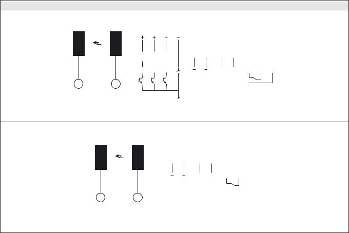
SGC 11 |
|
|
SPACEGUARD™ SERIES |
|||
|
|
|
|
|
|
|
Available Types |
|
|
|
|
||
Model |
|
Supply Voltage |
24 V ac |
115 V ac |
|
230 V ac |
|
|
|
|
|
|
|
Output |
|
Order Reference |
|
|
||
|
|
|
|
|
||
|
|
|
|
|
|
|
|
|
Relay and NPN |
SGC 11 A 302 |
SGC 11 A 301 |
|
SGC 11 A 300 |
SGC 11 A |
|
|
|
|
|
|
Relay |
SGC 11 A 502 |
SGC 11 A 501 |
|
SGC 11 A 500 |
||
|
|
|
||||
|
|
|
|
|
|
|
Note: 1. Detectors to be ordered separately. |
|
|
|
|
||
2. All controllers can be used with a 24 V dc supply voltage.
Wiring Diagrams
SGR |
SGT |
|
|
|
|
|
|
|
|
|
|
|
dc-supply |
|
ac-supply |
|
|
|
|
|
|
||||
|
|
|
|
|
|
|
|
|
|
|
|
|
|
|
|
|
|
|
relay output |
|
|||
|
|
|
|
|
|
|
|
|
|
|
|
|
|
|
|
|
|
|
|
|
|
|
|
|
TO |
|
AL |
|
SIG |
|
|
|
|
|
|
|
0 |
|
1 |
|
NC |
|
C |
|
NO |
||
|
|
|
|
|
|
|
|
|
|
|
24 VDC |
|
|
AC |
|
|
|
|
|
|
|||
|
|
|
|
|
|
|
|
|
|
|
SUPPLY |
|
SUPPLY |
|
|
|
|
|
|
||||
RX |
TX |
Relay and NPN output
SGR |
SGT |
dc-supply |
|
ac-supply |
|
|
|
|
|
|
|
|
||||
|
|
|
|
|
|
|
|
|
relay output |
|
|
|||
|
|
|
|
|
|
|
|
|
|
|
|
|
||
|
|
|
|
0 |
|
1 |
|
NC |
|
C |
|
NO |
||
24 VDC |
|
|
AC |
|
|
|
|
|
|
|
|
|||
SUPPLY |
|
SUPPLY |
|
|
|
|
|
|
|
|
||||
RX |
TX |
Relay output
124 I REMOTE LIGHT CURTAIN SYSTEMS
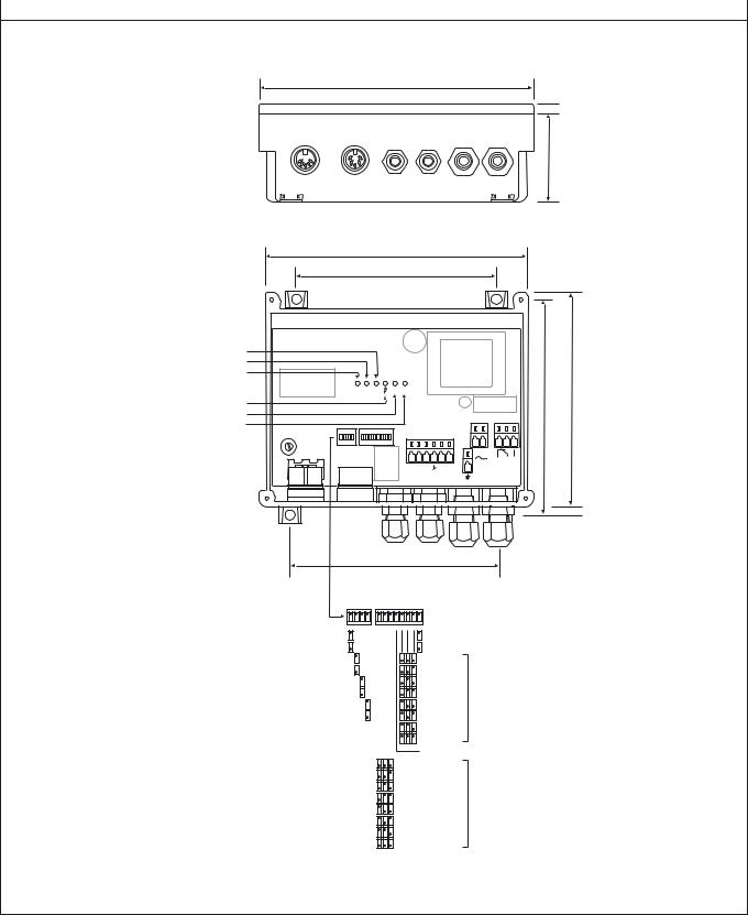
SPACEGUARD™ SERIES |
SGC 11 |
|
|
|
|
Dimensions and Descriptions |
|
|
|
|
|
177
 6
6
50
168
126
Ø 6 
Output indicator
Alarm indicator
Time-out indicator
|
TO AL SIG RXERR TXERR |
|
Power on indicator |
135 |
138 |
|
|
|
SGR sensor test indicator |
|
|
SGT sensor test indicator |
|
|
Sensitivity adjustment 
ON DIP |
ON |
DIP |
1 2 3 4 |
1 2 3 4 5 6 7 8 |
|
|
2 |
0 |
1 |
|
OR TO AL SIG – + |
|
AC |
|
RELAY |
SUPPLY |
SUPPLY |
|||
24VDC SUPPLY
137
Long range |
|
|
|
|
|
Light operated |
|
Short range |
|
|
|
|
|
Dark operated |
|
Diagnostic mode |
|
|
|
|
|
0,3 min |
|
Operation mode |
|
|
|
|
|
0,5 min |
|
Automatic sensitivity adjustment mode |
|
|
|
|
|
1,0 min |
|
Manual sensitivity adjustment mode |
|
|
|
|
|
2,0 min |
Time delay until |
Buzzer on |
|
|
|
|
|
3,0 min |
time-out activates |
Buzzer off |
|
|
|
|
|
5,0 min |
|
|
|
|
|
|
|
7,0 min |
|
|
|
|
|
|
|
10,0 min |
|
|
|
|
|
|
|
This switch is not used |
|
|
0 |
|
|||||
|
4 |
|
|||||
|
8 |
|
|||||
|
12 |
Max. number of |
|||||
|
16 |
channels time-out |
|||||
|
20 |
|
|||||
24
32
(Units in mm)
Telco reserves the right to change specifications without notice.
REMOTE LIGHT CURTAIN SYSTEMS I 125