

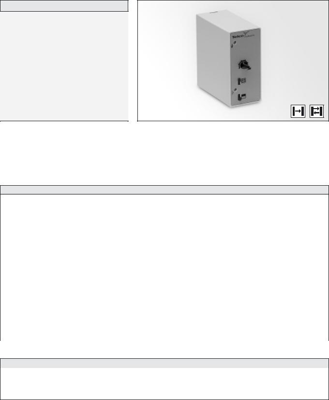
PHOTOELECTRIC AMPLIFIER SERIES
Telco’s photoelectric amplifier series performs as good today as it did when it first appeared almost 25 years ago. But while the simple design of this iconic product has remained the same in all that time, the technology on the inside has been constantly refined – so it continues to offer nothing less than the most reliable and powerful performance possible.

PHOTOELECTRIC AMPLIFIER SERIES |
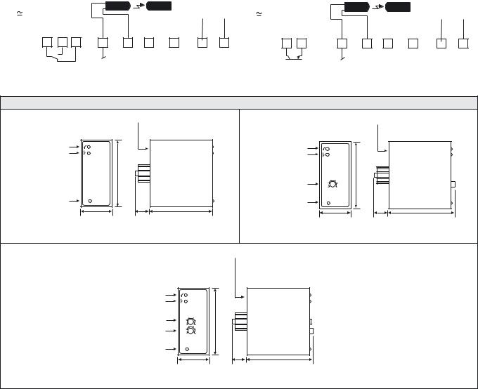
PA 01 |
|
|
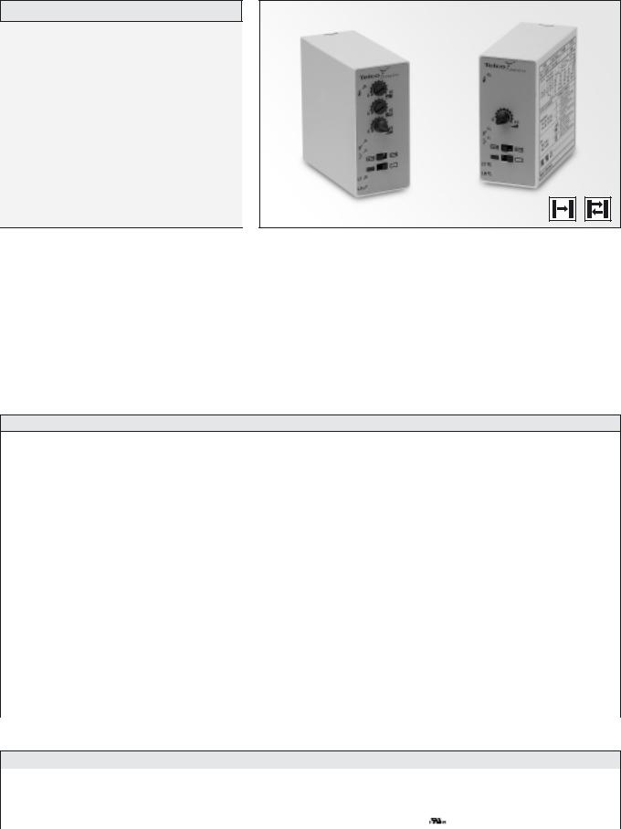
Description
Operation mode and max sensing range:
Thru beam: 0-45 m Diffuse proximity: 0-3,5 m
230 V ac, 115 V ac or 24 V ac/dc supply voltage
Automatic and/or manual sensitivity adjustment
Sensor LED-drive
Adjustable on/off time delay
1 relay or 1 transistor output
STF (Patented)
Switch selectable light or dark function
Switch selectable long or short range
Power, output and signal status indicators
Test input
11-pole DIN socket connection
The PA 01 is a 1-channel photoelectric amplifier, which is to be used in conjunction with a set of remote transmitter LT and receiver LR from the series 101, 100, 110 or 120.
This amplifier series offers a choice between automatic and/or manual sensitivity adjustment with or without a 0-10 sec on/off time delay via integral potentiometers located on the front panel of the amplifier. Output can be selected from either a relay or an NPN/PNP transistor output. Light or dark function and long or short range are switch selectable.
In automatic mode, set up is required. This is achieved by pressing the teach-in button located on the front panel. This unique feature ensures
that the transmitting power level is adjusted according to the application, thus achieving optimal hysteresis and excess gain. Once set up, the system will automatically compensate for moderate misalignment and contamination during operation. In manual mode, the teach-in button allows for an overall manual system test by temporarily disabling the transmitter. The sensor LED drive powers the optional monitor LEDs available on the remote sensors – output (LT) and power (LR).
The patented feature STF allows up to 3 identical systems to operate within a close distance of each other without optical cross talk as each system automatically maintains different transmitter frequencies.
Technical Data
Supply voltage |
|
115 V ac or 230 V ac |
|
|
|
||
|
12-30 V ac or 12-36 V dc |
||
|
|
||
|
|
|
|
Voltage tolerance |
|
+/– 15 % |
|
|
|
|
|
Current consumption |
|
Max. 2,5 VA |
|
|
|
|
|
Output |
Relay |
1 open / 1 close, 230 V ac / 3 A, 120 V ac / 5 A |
|
|
|
||
Transistor |
100 mA / 36 V dc |
||
|
|||
|
|
|
|
Power on indicator |
|
Green LED |
|
|
|
|
|
Output indicator |
|
Yellow LED |
|
|
|
|
|
Signal status indicator |
|
Green LED |
|
|
|
|
|
LR sensor failure indicator |
|
– |
|
|
|
|
|
LT sensor failure indicator |
|
– |
|
|
|
|
|
Sensor monitor LED drive |
|
The green monitor LED on the receiver indicates ‘Power ON’ |
|
|
The yellow monitor LED on the transmitter indicates ‘PA 01 output activated’ |
||
|
|
||
|
|
|
|
Hysteresis |
|
Approx. 20 % |
|
|
|
|
|
Operation frequency |
Relay |
11 Hz |
|
Transistor |
|
||
14 Hz |
|||
|
|||
|
|
|
|
Response time tON / tOFF |
Relay |
45 ms / 45 ms |
|
Transistor |
|
||
35 ms / 35 ms |
|||
|
|||
|
|
|
|
Delay tON / tOFF |
PA 01 C |
0 – 10 sec, adjustable |
|
Housing material |
|
Noryl |
|
|
|
|
Environmental Data
Temperature, operation |
– 10 to +55 ºC |
|
|
Temperature, storage |
– 40 to +80 ºC |
|
|
Sealing class |
IP 40 |
|
|
Approvals |
a |
|
|
REMOTE PHOTOELECTRIC SYSTEMS I 23
PA 01 |
|
|
|
|
|
|
|
|
|
|
|
|
|
|
|
|
|
|
|
|
|
|
|
|
|
|
|
|
|
|
|
|
|
|
|
|
|
|
PHOTOELECTRIC AMPLIFIER SERIES |
|||||||||||||||||||||||||||||||||||||||
|
|
|
|
|
|
|
|
|
|
|
|
|
|
|
|
|
|
|
|
|
|
|
|
|
|
|
|
|
|
|
|
|
|
|
|
|
|
|
|
|
|
|
|
|
|
|
|
|
|
|
|
|
|
|
|
|
|
|
|
|
|
|
|
|
|
|
|
|
|
|
|
|
|
|
|
|
|
|
|
|
|
|
|
|
|
|
|
|
|
|
|
|
|
|
|
|
|
|
|
|
|
|
|
|
|
|
|
|
|
|
|
|
|
|
|
|
|
|
|
|
|
|
|
|
|
|
|
|
|
|
|
|
|
|
|
|
|
|
|
|
|
|
|
|
|
|
|
|
|
|
|
|
|
|
|
|
|
Available Types |
|
|
|
|
|
|
|
|
|
|
|
|
|
|
|
|
|
|
|
|
|
|
|
|
|
|
|
|
|
|
|
|
|
|
|
|
|
|
|
|
|
|
|
|
|
|
|
|
|
|
|
|
|
|
|
|
|
|
|
|
|
|
|
|
|
|||||||||||||
|
|
|
|
|
|
|
|
|
|
|
|
|
|
|
|
|
|
|
|
|
|
|
|
|
|
|
|
|
|
|
|
|
Supply Voltage |
|
|
|
|
|
|
|
|
|
12 – 30 V ac |
|
|
|
|
115 V ac |
|
|
|
|
|
|
|
|
|
|
|
230 V ac |
|
|
|
|||||||||||||||
Model |
|
|
|
|
|
|
|
|
|
|
|
|
|
|
|
|
Connection |
|
|
|
|
|
|
|
|
|
|
|
|
|
|
12 – 36 V dc |
|
|
|
|
|
|
|
|
|
|
|
|
|
|
|
|
|
|
||||||||||||||||||||||||||||
|
|
|
|
|
|
|
|
|
|
|
|
|
|
|
|
|
|
|
|
|
|
|
|
|
|
|
|
|
|
|
|
|
|
|
|
|
|
|
|
|
|
|
|
|
|
|
|
|
|
|
|
|
|
|
|
|
|
|
|
|
||||||||||||||||||
|
|
|
|
|
|
|
|
|
|
|
|
|
|
|
|
|
|
|
|
|
|
|
|
|
|
|
|
|
|
|
|
|
|
|
Output |
|
|
|
|
|
|
|
|
|
|
|
|
|
|
|
|
|
|
Order Reference |
|
|
|
|
|
|
|
|
|
|
|
|
|
|
|
|||||||||
|
|
|
|
|
|
|
|
|
|
|
|
|
|
|
|
|
|
|
|
|
|
|
|
|
|
|
|
|
|
|
|
|
|
|
|
|
|
|
|
|
|
|
|
|
|
|
|
|
|
|
|
|
|
|
|
|
|
|
|
|
|
|
|
|
|
|
|
|
|
|
|
|
|
|
|
|
||
PA 01 A |
|
|
|
|
|
|
|
|
|
|
|
|
|
|
|
|
|
|
|
|
|
|
|
|
Relay |
|
|
|
|
|
|
|
|
|
PA 01 A 519 |
|
|
|
|
PA 01 A 511 |
|
|
|
|
|
|
|
|
|
|
|
PA 01 A 510 |
||||||||||||||||||||||||||
Automatic |
|
|
|
|
|
|
|
|
|
|
|
|
|
|
|
|
|
|
|
|
|
|
NPN and PNP |
|
|
|
|
|
|
|
|
|
PA 01 A 619 |
|
|
|
|
PA 01 A 611 |
|
|
|
|
|
|
|
|
|
|
|
PA 01 A 610 |
||||||||||||||||||||||||||||
|
|
|
|
|
|
|
|
|
|
|
|
|
|
|
|
|
|
|
|
|
|
|
|
|
|
|
|
|
|
|
|
|
|
|
|
|
|
|
|
|
|
|
|
|
|
|
|
|
|
|
|
|
|
|
|
|
|
|
|
|
|
|
|
|
|
|
|
|
|
|
|
|
|
|
|
|
||
PA 01 B |
|
|
|
|
|
|
|
|
|
11-pole DIN socket |
|
|
|
|
|
|
|
Relay |
|
|
|
|
|
|
|
|
|
PA 01 B 519 |
|
|
|
|
PA 01 B 511 |
|
|
|
|
|
|
|
|
|
|
|
PA 01 B 510 |
|||||||||||||||||||||||||||||||||
Automatic/Manual |
|
|
|
|
|
|
|
|
|
|
|
NPN and PNP |
|
|
|
|
|
|
|
|
|
PA 01 B 619 |
|
|
|
|
PA 01 B 611 |
|
|
|
|
|
|
|
|
|
|
|
PA 01 B 610 |
|||||||||||||||||||||||||||||||||||||||
|
|
|
|
|
|
|
|
|
|
|
|
|
|
|
|
|
|
|
|
|
|
|
|
|
|
|
|
|
|
|
|
|
|
|
|
|
|
|
|
|
|
|
||||||||||||||||||||||||||||||||||||
|
|
|
|
|
|
|
|
|
|
|
|
|
|
|
|
|
|
|
|
|
|
|
|
|
|
|
|
|
|
|
|
|
|
|
|
|
|
|
|
|
|
|
|
|
|
|
|
|
|
|
|
|
|
|
|
|
|
|
|
|
|
|
|
|
|
|
|
|
|
|
|
|
|
|
|
|
||
PA 01 C |
|
|
|
|
|
|
|
|
|
|
|
|
|
|
|
|
|
|
|
|
|
|
|
|
Relay |
|
|
|
|
|
|
|
|
|
PA 01 C 519 |
|
|
|
|
PA 01 C 511 |
|
|
|
|
|
|
|
|
|
|
|
PA 01 C 510 |
||||||||||||||||||||||||||
Automatic/Manual |
|
|
|
|
|
|
|
|
|
|
|
|
|
|
|
|
|
|
|
|
|
|
|
|
|
|
|
|
|
|
|
|
|
|
|
|
|
|
|
|
|
|
|
|
|
|
|
|
|
|
|
|
|
|
|
|
|
|
|
|
|
|
|
|||||||||||||||
|
|
|
|
|
|
|
|
|
|
|
|
|
|
|
|
|
NPN and PNP |
|
|
|
|
|
|
|
|
|
PA 01 C 619 |
|
|
|
|
PA 01 C 611 |
|
|
|
|
|
|
|
|
|
|
|
PA 01 C 610 |
||||||||||||||||||||||||||||||||||
on/off delay |
|
|
|
|
|
|
|
|
|
|
|
|
|
|
|
|
|
|
|
|
|
|
|
|
|
|
|
|
|
|
|
|
|
|
|
|
|
|
|
|
|
|
|
|
|
|
||||||||||||||||||||||||||||||||
|
|
|
|
|
|
|
|
|
|
|
|
|
|
|
|
|
|
|
|
|
|
|
|
|
|
|
|
|
|
|
|
|
|
|
|
|
|
|
|
|
|
|
|
|
|
|
|
|
|
|
|
|
|
|
|
|
|
|
|
|
|
|
|
|
|
|
|
|
|
|
|
|
|
|
|
|
|
|
Note: Remote sensors and 11-pole DIN socket to be ordered separately. |
|
|
|
|
|
|
|
|
|
|
|
|
|
|
|
|
|
|
|
|
|
|
|
|
|
|
|
|
|
|
|
|
|
|
|
|
|
|
|
|
|
|
|
|
||||||||||||||||||||||||||||||||||
|
|
|
|
|
|
|
|
|
|
|
|
|
|
|
|
|
|
|
|
|
|
|
|
|
|
|
|
|
|
|
|
|
|
|
|
|
|
|
|
|
|
|
|
|
|
|
|
|
|
|
|
|
|
|
|
|
|
|
|
|
|
|
|
|
|
|
|
|
|
|
|
|
|
|||||
Applicable Remote Sensors and Ranges |
|
|
|
|
|
|
|
|
|
|
|
|
|
|
|
|
|
|
|
|
|
|
|
|
|
|
|
|
|
|
|
|
|
|
|
|
|
|
|
|
|
|
|
|
|
|
|
|
|
|
|
|
|
|
|
|||||||||||||||||||||||
Series |
|
|
|
|
|
|
|
|
|
|
|
|
|
|
|
|
|
|
|
|
|
|
|
|
|
|
Thru Beam |
|
|
|
|
|
|
|
|
|
|
|
|
|
|
|
|
|
|
|
Diffuse Proximity |
|
|
|
|
|
|
|
|
|||||||||||||||||||||||
|
|
|
|
|
|
|
|
|
|
|
|
|
|
|
|
|
|
|
|
|
|
|
|
|
|
|
|
|
|
|
|
|
|
|
|
|
|
|
|
|
|
|
|
|
|
|
|
|
|
|
|
|
|
|
|
|
|
|
|
|
|
|
|
|
|
|
|
|
|
|
|
|
|
|
|
|
||
101 |
|
|
|
|
|
|
|
|
|
|
|
|
|
|
|
|
|
|
|
|
|
|
|
|
|
|
|
8 m |
|
|
|
|
|
|
|
|
|
|
|
|
|
|
|
|
|
|
|
|
|
|
|
|
|
0,6 m |
|
|
|
|
|
|
|
|
||||||||||||||||
|
|
|
|
|
|
|
|
|
|
|
|
|
|
|
|
|
|
|
|
|
|
|
|
|
|
|
|
|
|
|
|
|
|
|
|
|
|
|
|
|
|
|
|
|
|
|
|
|
|
|
|
|
|
|
|
|
|
|
|
|
|
|
|
|
|
|
|
|
|
|
|
|
|
|
|
|
||
100 |
|
|
|
|
|
|
|
|
|
|
|
|
|
|
|
|
|
|
|
|
|
|
|
|
|
|
|
10 m |
|
|
|
|
|
|
|
|
|
|
|
|
|
|
|
|
|
|
|
|
|
|
|
|
|
0,7 m |
|
|
|
|
|
|
|
|
||||||||||||||||
|
|
|
|
|
|
|
|
|
|
|
|
|
|
|
|
|
|
|
|
|
|
|
|
|
|
|
|
|
|
|
|
|
|
|
|
|
|
|
|
|
|
|
|
|
|
|
|
|
|
|
|
|
|
|
|
|
|
|
|
|
|
|
|
|
|
|
|
|
|
|
|
|
|
|
|
|
||
110 |
|
|
|
|
|
|
|
|
|
|
|
|
|
|
|
|
|
|
|
|
|
|
|
|
|
|
|
23 m |
|
|
|
|
|
|
|
|
|
|
|
|
|
|
|
|
|
|
|
|
|
|
|
|
|
1,6 m |
|
|
|
|
|
|
|
|
||||||||||||||||
|
|
|
|
|
|
|
|
|
|
|
|
|
|
|
|
|
|
|
|
|
|
|
|
|
|
|
|
|
|
|
|
|
|
|
|
|
|
|
|
|
|
|
|
|
|
|
|
|
|
|
|
|
|
|
|
|
|
|
|
|
|
|
|
|
|
|
|
|
|
|
|
|
|
|
|
|
||
120 |
|
|
|
|
|
|
|
|
|
|
|
|
|
|
|
|
|
|
|
|
|
|
|
|
|
|
|
45 m |
|
|
|
|
|
|
|
|
|
|
|
|
|
|
|
|
|
|
|
|
|
|
|
|
|
3,5 m |
|
|
|
|
|
|
|
|
||||||||||||||||
|
|
|
|
|
|
|
|
|
|
|
|
|
|
|
|
|
|
|
|
|
|
|
|
|
|
|
|
|
|
|
|
|
|
|
|
|
|
|
|
|
|
|
|
|
|
|
|
|
|
|
|
|
|
|
|
|
|
|
|
|
|
|
|
|
|
|
|
|
|
|
|
|
|
|
|
|
||
|
|
|
|
|
|
|
|
|
|
|
|
|
|
|
|
|
|
|
|
|
|
|
|
|
|
|
|
|
|
|
|
|
|
|
|
|
|
|
|
|
|
|
|
|
|
|
|
|
|
|
|
|
|
|
|
|
|
|
|
|
|
|
|
|
|
|
|
|
|
|
|
|
|
|
|
|
||
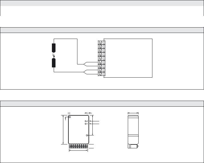
Wiring Diagrams |
|
|
|
|
|
|
|
|
|
|
|
|
|
|
|
|
|
|
|
|
|
|
|
|
|
|
|
|
|
|
|
|
|
|
|
|
|
|
|
|
|
|
|
|
|
|
|
|
|
|
|
|
|
|
|
|
|
|
|
|
|
|
|
|||||||||||||||
|
|
|
|
|
|
|
|
|
|
|
|
|
|
|
|
|
|
|
|
LT |
|
|
|
|
LR |
|
|
|
|
Test- |
|
|
|
|
|
|
|
|
|
|
|
|
|
|
|
|
|
|
|
|
|
|
|
LT |
|
|
|
LR |
|
|
|
|
Test- |
|
|
|
||||||||||||
|
|
|
|
|
|
|
|
|
|
|
|
|
|
|
|
|
|
|
|
|
|
|
|
|
|
|
|
|
|
|
|
|
|
|
|
|
|
|
|
|
|
|
|
|
|
|
|
|
|
|
|
|
|
|
|
|
|
|
||||||||||||||||||||
|
|
|
|
|
|
|
|
|
|
|
|
|
|
|
|
|
|
|
|
|
|
|
|
|
|
|
|
|
|
|
|
|
|
|
|
|
|
|
|
|
|
|
|
|
|
|
|
|
|
|
|
|
|
|
|
|
|
|
|
|
|
|
|
|
|
|
|
|
|
|
|
|
||||||
|
|
|
|
|
|
|
|
|
|
|
|
Relay |
|
|
|
|
|
|
|
|
|
|
|
|
|
|
|
|
input |
Invert |
|
|
|
|
|
|
|
|
|
|
|
|
|
|
|
|
|
|
|
|
|
|
|
|
|
|
|
|
|
|
|
|
|
|
|
input |
Invert |
|||||||||||
|
|
|
|
|
|
|
|
|
|
|
C |
NO |
NC |
Black |
|
Red |
|
|
|
Yellow |
|
|
Shield |
|
|
|
|
|
|
|
|
|
|
|
|
|
|
NPN/PNP |
Black |
|
Red |
|
|
Yellow |
|
Shield |
|
|
|
|||||||||||||||||||||||||||||
|
|
|
|
|
|
|
|
|
|
|
|
|
|
|
|
|
|
|
|
|
|
|
|
|
|
|
|
|
|
|
|
|
|
|
|
|
|
|
|
|
|
|
|
|
|
|
|
|
|
|
|
|
|
|
|
|
|
|
|
|
|
|
|
|
|
|
|
|||||||||||
|
|
|
|
|
|
|
|
|
|
|
|
|
|
|
|
|
|
|
|
|
|
|
|
|
|
|
|
|
|
|
|
|
|
|
|
|
|
|
|
|
|
|
|
|
|
|
|
|
|
|
|
|
|
|
|
|
|
|
|
|
|
|
|
|
|
|
|
|
|
|
|
|
|
|
|
|
||
|
2 |
|
|
10 |
|
1 |
|
|
3 |
|
4 |
|
|
7 |
|
|
5 |
|
6 |
|
|
8 |
|
|
9 |
|
|
11 |
|
|
2 |
|
|
10 |
|
1 |
|
|
3 |
|
|
7 |
|
|
5 |
|
|
6 |
|
|
8 |
|
|
9 |
|
|
11 |
|
||||||||||||||||||||
|
|
|
|
|
|
|
|
|
|
|
|
|
|
|
|
|
|
|
Relay output |
|
|
|
|
|
|
|
|
|
|
|
|
|
|
|
|
|
|
|
|
|
|
|
|
|
|
|
|
|
|
|
Transistor output |
|
|
|
|
|
|
|
|
|
|
|
|
|
|
|
|
|
||||||||||
|
|
|
|
|
|
|
|
|
|
|
|
|
|
|
|
|
|
|
|
|
|
|
|
|
|
|
|
|
|
|
|
|
|
|
|
|
|
|
|
|
|
|
|
|
|
|
|
|
|
|
|
|
|
|
|
|
|
|
|
|
|
|
|
|
|
|
|
|
|
|
|
|
|
|
|
|
|
|
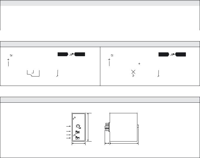
Dimensions and Descriptions
|
|
Dip switch selection for: |
|
|
|
|
|
Light/dark mode |
|
|
|
|
Long/short range |
|
Signal status indicator |
|
|
Signal status indicator |
|
Output indicator |
|
|
Output indicator |
|
|
76 |
|
|
76 |
|
|
|
Manual switch and |
MAN |
|
|
|
AUTO |
|
|
|
|
sensitivity adjustment |
|
Teach in |
RESET/TEST |
|
Teach in |
RESET/TEST |
|
35 |
13 |
74 |
35 |
|
|
|
|
|
|
PA 01 A |
|
(Units in mm) |
PA 01 B |
|
|
|
|
|
Dip switch selection for:
Light/dark mode
Long/short range
13 |
78 |
(Units in mm)
Signal status indicator
Output indicator
On/off delay adjustment
Manual switch and sensitivity adjustment
Teach in
TIME
MAN AUTO
Dip switch selection for: On/off delay Long/short range
Note: dark/light selection via 11 pole socket when pin 11 is shorted to 7
|
76 |
|
RESET/TEST |
|
|
35 |
13 |
78 |
PA 01 C
(Units in mm)
Telco reserves the right to change specifications without notice.
24 I REMOTE PHOTOELECTRIC SYSTEMS

PHOTOELECTRIC AMPLIFIER SERIES |
PA 09 |
|
|
Description
Operation mode and max sensing range:
Thru beam: 5 m Diffuse proximity: 0,4 m
12 or 24 V dc supply voltage
1 relay output acc. to UNI 8612
Power and output indicators
Screw terminals connection
The PA 09 is a 1-channel photoelectric amplifier, which is to be used in conjunction with a set of remote transmitter LT and receiver LR from the series 101.
This amplifier series is low cost, designed especially for the elevator and door industries, offering a relay output, designed according to the UNI 8612 standard whereby 2 relays are mounted in series.
Technical Data
Supply voltage |
12 V dc or 24 V dc |
|
|
Voltage tolerance @ 12 V dc |
–10 / +20 % |
Voltage tolerance @ 24 V dc |
|
–15 / +20 % |
|
|
|
Current consumption |
Max. 2 VA |
|
|
Output relay |
24 V dc / 2A |
|
|
Power on indicator |
Green LED |
|
|
Output indicator |
Yellow LED |
|
|
Signal status indicator |
– |
|
|
LR sensor failure indicator |
– |
|
|
LT sensor failure indicator |
– |
|
|
Sensor monitor LED drive |
– |
|
|
Hysteresis |
Approx. 30 % |
|
|
Operation frequency |
10 Hz |
|
|
Response time tON / tOFF |
50 ms / 50 ms |
Delay tON / tOFF |
– |
Housing material |
Polystyrene |
|
|
Environmental Data
Temperature, operation |
– 10 to +50 ºC |
|
|
Temperature, storage |
– 40 to +80 ºC |
|
|
Sealing class |
IP 40 |
|
|
Approvals |
a |
|
|
REMOTE PHOTOELECTRIC SYSTEMS I 25
PA 09 |
|
|
PHOTOELECTRIC AMPLIFIER SERIES |
|||
|
|
|
|
|
|
|
|
|
|
|
|
|
|
Available Types |
|
|
|
|
|
|
Model |
Connection |
Supply Voltage |
|
12 V dc |
|
24 V dc |
|
|
|
|
|
||
Output |
|
|
Order Reference |
|||
|
|
|
|
|||
|
|
|
|
|
|
|
PA 09 B |
Screw terminals |
Relay |
|
PA 09 B 504 |
|
PA 09 B 503 |
|
|
|
|
|
|
|
Note: Remote sensors to be ordered separately.
Applicable Remote Sensors and Ranges
Series |
Thru Beam |
Diffuse Proximity |
|
|
|
101 |
5 m |
0,4 m |
|
|
|
Wiring Diagrams
LR LT
|
1 |
relay C |
|
|
2 |
relay NC |
|
|
3 |
relay NO |
|
|
4 |
power – |
|
Black |
5 |
power + |
|
76 } LT |
|||
Red |
|||
Shield |
98 } LR |
||
Yellow |
|||
Relay output
Dimensions and Descriptions

 5
5
Ø 5
83
Relay
C |
NC |
NO |
1 |
2 |
3 |
Telco reserves the right to change specifications without notice.
22
5
Power on indicator
Output indicator
52
Ø 5
– |
+ |
LT |
LR |
||
Power |
Power |
Black |
Red |
Shield |
Yellow |
4 |
5 |
6 |
7 |
8 |
9 |
 10
10
53
PA 09 B |
(Units in mm) |
26 I REMOTE PHOTOELECTRIC SYSTEMS
PHOTOELECTRIC AMPLIFIER SERIES |
PA 10 |
|
|
Description
Operation mode and max sensing range:
Thru beam: 0-60 m Diffuse proximity: 0-4 m
230 V ac, 115 V ac, 24 V ac or 24 V dc supply voltage
Manual sensitivity adjustment
1 relay or 1 transistor output
Switch selectable light or dark function
Switch selectable long or short range
Power and output indicators
11-pole DIN socket connection
The PA 10 is a 1-channel photoelectric amplifier. The PA 10 A is to be used in conjunction with a remote transmitter LT and receiver LR from series 101, whilst the PA 10 B is intended for use with series 100, 110, and 120.
This amplifier series offers manual sensitivity adjustment via an integral potentiometer located on the front panel of the amplifier. Output can be selected from either a relay or an NPN/PNP transistor output. Light or dark function and long or short range are switch selectable.
Technical Data
Supply voltage |
24 V dc, 24 V ac, 115 V ac or 230 V ac |
|
|
|
|
Voltage tolerance |
+/– 15 % |
|
|
|
|
Current consumption |
Max. 3,2 VA |
|
|
|
|
Relay |
1 open / 1 close, 250 V ac / 3 A, 120 V ac / 5 A |
|
Output |
|
|
|
||
Transistor |
40 mA / 30 V dc |
|
|
|
|
Power on indicator |
Green LED |
|
|
|
|
Output indicator |
Red LED |
|
|
|
|
Signal level indicator |
– |
|
|
|
|
LR sensor failure indicator |
– |
|
|
|
|
LT sensor failure indicator |
– |
|
|
|
|
Sensor monitor LED drive |
– |
|
|
|
|
Hysteresis |
Approx. 40 % |
|
|
|
|
Relay |
10 Hz |
|
Operation frequency |
|
|
|
||
Transistor |
12 Hz |
|
|
|
|
Relay |
50 ms / 50 ms |
|
Response time tON / tOFF |
|
|
40 ms / 40 ms |
||
Transistor |
||
Delay tON / tOFF |
– |
|
Housing material |
Noryl |
|
|
|
Environmental Data
Temperature, operation |
– 10 to +50 ºC |
|
|
Temperature, storage |
– 40 to +80 ºC |
|
|
Sealing class |
IP 40 |
|
|
Approvals |
a b d |
|
|
REMOTE PHOTOELECTRIC SYSTEMS I 27
PA 10 |
|
|
|
PHOTOELECTRIC AMPLIFIER SERIES |
|||
|
|
|
|
|
|
|
|
|
|
|
|
|
|
|
|
Available Types |
|
|
|
|
|
|
|
Model |
Connection |
Supply Voltage |
24 V dc |
24 V ac |
115 V ac |
230 V ac |
|
|
|
|
|
|
|||
Output |
|
Order Reference |
|
||||
|
|
|
|
||||
|
|
|
|
|
|
|
|
PA 10 A |
|
Relay |
PA 10 A 513 |
PA 10 A 512 |
PA 10 A 511 |
PA 10 A 510 |
|
|
|
|
|
|
|
||
11-pole DIN socket |
NPN and PNP |
PA 10 A 613 |
PA 10 A 612 |
PA 10 A 611 |
PA 10 A 610 |
||
|
|||||||
|
|
|
|
|
|
||
PA 10 B |
Relay |
PA 10 B 513 |
PA 10 B 512 |
PA 10 B 511 |
PA 10 B 510 |
||
|
|||||||
|
|
|
|
|
|
||
|
NPN and PNP |
PA 10 B 613 |
PA 10 B 612 |
PA 10 B 611 |
PA 10 B 610 |
||
|
|
||||||
|
|
|
|
|
|
|
|
Note: Remote sensors and 11-pole DIN socket to be ordered separately.
Applicable Remote Sensors and Ranges
Series |
Thru Beam |
Diffuse Proximity |
|
|
|
101 (only PA 10 A) |
11 m |
0,9 m |
|
|
|
100 (only PA 10 B) |
15 m |
1,1 m |
|
|
|
110 (only PA 10 B) |
35 m |
2 m |
|
|
|
120 (only PA 10 B) |
60 m |
4 m |
|
|
|
Wiring Diagrams
|
|
|
|
|
|
|
|
|
|
|
|
|
|
|
|
|
LT |
|
|
|
LR |
|
|
|
|
|
|
|
|
|
|
|
|
|
|
|
|
|
|
|
|
|
|
|
|
LT |
|
|
|
|
LR |
|
|
|
|
|
||||
|
|
|
|
|
|
|
|
Relay |
|
|
|
|
|
|
|
|
|
|
|
|
|
|
|
|
|
|
|
|
|
|
|
|
|
|
|
|
|
|
|
|
|
|
|
|
|
|
|
|
|
|
|
|
|
|
|
|
|
|
||
|
|
|
|
|
|
|
C |
|
NO |
NC |
Black |
|
Red |
|
|
|
Yellow |
|
|
Shield |
|
|
|
|
|
|
NPN/PNP |
|
|
Black |
|
Red |
|
|
|
|
Yellow |
|
|
Shield |
||||||||||||||||||||
|
|
|
|
|
|
|
|
|
|
|
|
|
|
|
|
|
|
|
|
|
|
|
|
|
|
|
|
|
|
|
|
|
|
|
|
|
|
|
|
|
|
|
|
|
|
|
|
|
|
|
|
|
|
|
|
|
|
|
|
|
2 |
|
10 |
|
1 |
|
3 |
|
4 |
|
|
7 |
|
5 |
|
6 |
|
8 |
|
|
2 |
|
10 |
|
9 |
|
|
|
11 |
|
|
7 |
|
5 |
|
6 |
|
|
8 |
|
|
||||||||||||||||||||
|
|
|
|
|
|
|
|
|
|
|
|
|
|
|
|
|
|
|
|
|
|
|
|
|
|
|
|
|
|
|
|
|
|
|
|
|
|
|
|
|
|
|
|
|
|
|
|
|
|
|
|
|
|
|
|
|
|
|
|
|
|
|
|
|
|
|
|
|
|
|
|
|
|
|
|
|
|
|
|
|
|
|
|
|
|
|
|
|
|
|
|
|
|
|
|
|
|
|
|
|
|
|
|
|
|
|
|
|
|
|
|
|
|
|
|
|
|
|
|
|
|
Relay output |
Transistor output |
Dimensions and Descriptions
Power on indicator 
Sensitivity adjustment
Long/short range
Output indicator
Light/dark switch
35 |
13 |
78 |
PA 10 A/B |
(Units in mm) |
|
Telco reserves the right to change specifications without notice.
28 I REMOTE PHOTOELECTRIC SYSTEMS
PHOTOELECTRIC AMPLIFIER SERIES |
PA 11 |
|
|
Description
Operation mode and max sensing range:
Thru beam: 0-70 m Diffuse proximity: 0-5 m
230 V ac, 115 V ac, 24 V ac or 24 V dc supply voltage
Manual sensitivity adjustment
Sensor LED-drive
Automatic sensor test
Adjustable on/off time delay
1 relay and/or 1 transistor output
Switch selectable light or dark function
Switch selectable long or short range
Power, output and signal level indicators
11-pole DIN socket connection
The PA 11 is a 1-channel photoelectric amplifier, which is to be used in conjunction with a set of remote transmitter LT and receiver LR from the series 100, 110 and 120.
This amplifier series offers manual sensitivity adjustment via integral potentiometers located on the front panel of the amplifier. Output can be selected from either a relay and NPN or NPN and PNP transistor outputs with or without a 0-10 sec on/off time delay. Light or dark function and long or short range are switch selectable.
The microprocessor controlled sensor test ensures that the system will automatically detect and indicate a faulty transmitter or receiver – cable break or electrical failure – during operation, through the relevant LED located on the front panel. The sensor LED drive powers the optional monitor LEDs available on the remote sensors – output (LT) and power (LR).
Technical Data
Supply voltage |
|
24 V dc, 24 V ac, 115 V ac or 230 V ac |
|
|
|
|
|
Voltage tolerance |
|
+/– 15 % |
|
|
|
|
|
Current consumption |
|
Max. 3,5 VA |
|
|
|
|
|
Output |
Relay |
1 open / 1 close, 250 V ac / 3 A, 120 V ac / 5 A |
|
|
|
||
Transistor |
60 mA / 30 V dc |
||
|
|||
|
|
|
|
Power on indicator |
|
Green LED |
|
|
|
|
|
Output indicator |
|
Yellow LED |
|
|
|
|
|
Signal level indicator |
|
Green LED |
|
|
|
|
|
LR sensor failure indicator |
|
Red LED |
|
|
|
|
|
LT sensor failure indicator |
|
Red LED |
|
|
|
|
|
Sensor monitor LED drive |
|
The green monitor LED on the receiver indicates ‘Power ON’ |
|
|
The yellow monitor LED on the transmitter indicates ‘PA 11 output activated’ |
||
|
|
||
|
|
|
|
Hysteresis |
|
Approx. 45 % |
|
|
|
|
|
Operation frequency |
Relay |
14 Hz |
|
|
|
||
Transistor |
20 Hz |
||
|
|||
|
|
|
|
Response time tON / tOFF |
Relay |
35 ms / 35 ms |
|
Transistor |
|
||
25 ms / 25 ms |
|||
|
|||
|
|
|
|
Delay tON / tOFF |
PA 11 A |
0 – 10 sec, adjustable |
|
Housing material |
|
Noryl |
|
|
|
|
Environmental Data
Temperature, operation |
–10 to +50 ºC |
|
|
Temperature, storage |
– 40 to +80 ºC |
|
|
Sealing class |
IP 40 |
|
|
Approvals |
a |
|
|
REMOTE PHOTOELECTRIC SYSTEMS I 29

PA11 |
|
|
|
PHOTOELECTRIC AMPLIFIER SERIES |
|||
|
|
|
|
|
|
|
|
|
|
|
|
|
|
|
|
Available Types |
|
|
|
|
|
|
|
Model |
Connection |
Supply Voltage |
24 V dc |
24 V ac |
115 V ac |
230 V ac |
|
|
|
|
|
|
|||
Output |
|
Order Reference |
|
||||
|
|
|
|
||||
|
|
|
|
|
|
|
|
PA 11 A |
|
Relay and NPN |
PA 11 A 303T |
PA 11 A 302T |
PA 11 A 301T |
PA 11 A 300T |
|
On/Off delay |
11-pole DIN socket |
NPN and PNP |
PA 11 A 403T |
PA 11 A 402T |
PA 11 A 401T |
PA 11 A 400T |
|
|
|
|
|
|
|
||
PA 11 B |
Relay and NPN |
PA 11 B 303T |
PA 11 B 302T |
PA 11 B 301T |
PA 11 B 300T |
||
|
|||||||
|
|
|
|
|
|
||
|
NPN and PNP |
PA 11 B 403T |
PA 11 B 402T |
PA 11 B 401T |
PA 11 B 400T |
||
|
|
||||||
|
|
|
|
|
|
|
|
Note: Remote sensors and 11-pole DIN socket to be ordered separately.
Applicable Remote Sensors and Ranges
Series |
Thru Beam |
Diffuse Proximity |
|
|
|
100 |
18 m |
1,1 m |
|
|
|
110 |
40 m |
2 m |
|
|
|
120 |
70 m |
5 m |
|
|
|
Wiring Diagrams
Load Supply |
LT |
LR |
Load Supply |
LR |
|
LT |
|||
Supply |
|
|
Supply |
|
|
|
Voltage |
|
|
Voltage |
|
|
|
|
|
|
Relay |
|
|
Black |
Red |
Yellow |
Shield |
|
|
|
|
|
Black |
Red |
Yellow |
Shield |
|
|
|
|
|
|
|
|
|
|
|
||||||||
|
|
C |
NO |
NC |
|
NPN |
|
|
|
|
|
NPN |
|
|
PNP |
|
|
|
|
|
|
|
|
|
|
|
|
|
|
|
|
|
|
|
|||
2 |
10 |
1 |
3 |
4 |
9 |
7 |
5 |
6 |
8 |
2 |
10 |
9 |
1 |
3 |
7 |
5 |
6 |
8 |
Relay output |
Transistor output |
Dimensions and Descriptions
Power on indicator
On delay adjustment
Off delay adjustment
Sensitivity adjustment
Signal status indicator Output indicator Long/short switch Light/dark switch
LT/LR sensor test indicator
|
|
|
Power on indicator |
|
|
|
|
76 |
|
Sensitivity adjustment |
|
|
|
|
|
Signal status indicator |
|
|
|
|
|
|
|
|
|
|
|
|
|
|
Output indicator |
|
|
|
|
|
|
Long/short switch |
|
|
|
|
|
|
Light/dark switch |
|
|
|
LT |
|
|
LT/LR sensor test indicator |
LT |
|
|
LR |
|
|
|
LR |
|
|
35 |
13 |
78 |
|
35 |
13 |
78 |
|
PA 11 A |
|
|
|
PA 11 B |
|
(Units in mm) |
(Units in mm) |
Telco reserves the right to change specifications without notice.
30 I REMOTE PHOTOELECTRIC SYSTEMS