

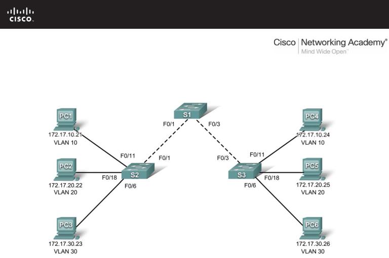
PT Activity 3.4.2: Troubleshooting a VLAN Implementation
Topology Diagram
Addressing Table
|
Device |
|
|
IP Address |
|
|
Subnet Mask |
|
|
Default Gateway |
|
|
|
|
|
|
|
|
|
||||
|
|
|
|
|
|
|
|
|
|
|
|
|
PC1 |
172.17.10.21 |
|
255.255.255.0 |
|
172.17.10.1 |
|
||||
|
|
|
|
|
|
|
|
||||
|
PC2 |
172.17.20.22 |
|
255.255.255.0 |
|
172.17.20.1 |
|
||||
|
|
|
|
|
|
|
|
||||
|
PC3 |
172.17.30.23 |
|
255.255.255.0 |
|
172.17.30.1 |
|
||||
|
|
|
|
|
|
|
|
||||
|
PC4 |
172.17.10.24 |
|
255.255.255.0 |
|
172.17.10.1 |
|
||||
|
|
|
|
|
|
|
|
||||
|
PC5 |
172.17.20.25 |
|
255.255.255.0 |
|
172.17.20.1 |
|
||||
|
|
|
|
|
|
|
|
||||
|
PC6 |
172.17.30.26 |
|
255.255.255.0 |
|
172.17.30.1 |
|
||||
|
|
|
|
|
|
|
|
|
|
|
|
Learning Objectives
•Test connectivity.
•Investigate connectivity problems by gathering data.
•Implement the solution and test connectivity.
All contents are Copyright © 1992–2007 Cisco Systems, Inc. All rights reserved. This document is Cisco Public Information. |
Page 1 of 3 |

CCNA Exploration |
|
LAN Switching and Wireless: VLANs |
PT Activity 3.4.2: Troubleshooting a VLAN Implementation |
Introduction
In this activity, you will troubleshoot connectivity problems between PCs on the same VLAN. The activity is complete when you achieve 100% and the PCs can ping the other PCs on the same VLAN. Any solution you implement must conform to the topology diagram.
Task 1: Test Connectivity between PCs on the same VLAN
From the Command Prompt on each PC, ping between PCs on the same VLAN. The following tests should be successful at the conclusion of this activity. However, these tests will fail at this point.
•PC1 cannot ping PC4.
•PC2 cannot ping PC5.
•PC3 cannot ping PC6.
Task 2: Gather Data on the Problem
Step 1. Verify the configuration on the PCs.
Are the following configurations for each PC correct?
•IP address
•Subnet mask
•Default gateway
Step 2. Verify the configuration on the switches.
Are the configurations on the switches correct? Be sure to verify the following:
•Ports assigned to the correct VLANs.
•Ports configured for the correct mode.
•Ports connected to the correct device.
Step 3: Document the problem and suggest solutions.
What are the reasons why connectivity failed between the PCs? What are the solutions? There could be more than one problem and more than one solution. All solutions must conform to the topology diagram.
PC1 to PC4
Problem: ___________________________________________________________________________
Solution: ___________________________________________________________________________
PC2 to PC5
Problem: ___________________________________________________________________________
Solution: ___________________________________________________________________________
PC3 to PC6
Problem: ___________________________________________________________________________
Solution: ___________________________________________________________________________
All contents are Copyright © 1992–2007 Cisco Systems, Inc. All rights reserved. This document is Cisco Public Information. |
Page 2 of 3 |

CCNA Exploration |
|
LAN Switching and Wireless: VLANs |
PT Activity 3.4.2: Troubleshooting a VLAN Implementation |
Task 3: Implement the Solution and Test Connectivity
Step 1: Make changes according to the suggested solutions in Task 2.
Step 2: Test connectivity between PCs on the same VLAN.
If you change any IP configurations, you should create new pings, because the prior pings use the old IP address.
•PC1 should be able to ping PC4.
•PC2 should be able to ping PC5.
•PC3 should be able to ping PC6.
Can PC1 ping PC4? ___________
Can PC2 ping PC5? ___________
Can PC3 ping PC6? ___________
If any pings fail, return to Task 2 to continue troubleshooting.
Step 3. Check completion percentage.
Your completion percentage should be 100%. If not, return to Step 1 and continue to implement your suggested solutions. Information found via the Assessment Items tab under Check Results has been hidden which will prevent viewing any required components that are still incomplete.
All contents are Copyright © 1992–2007 Cisco Systems, Inc. All rights reserved. This document is Cisco Public Information. |
Page 3 of 3 |
PT Activity 3.5.1: Basic VLAN Configuration
Topology Diagram
Addressing Table
|
Device |
|
|
Interface |
|
|
IP Address |
|
|
Subnet Mask |
|
|
Default Gateway |
|
|
|
|
|
|
|
|
|
|
|
|||||
|
|
|
|
|
|
|
|
|
|
|
|
|
|
|
|
S1 |
|
VLAN 99 |
172.17.99.11 |
|
255.255.255.0 |
|
|
N/A |
|||||
|
|
|
|
|
|
|
|
|
|
|||||
|
S2 |
|
VLAN 99 |
172.17.99.12 |
|
255.255.255.0 |
|
|
N/A |
|||||
|
|
|
|
|
|
|
|
|
|
|||||
|
S3 |
|
VLAN 99 |
172.17.99.13 |
|
255.255.255.0 |
|
|
N/A |
|||||
|
|
|
|
|
|
|
|
|
|
|||||
|
PC1 |
|
NIC |
172.17.10.21 |
|
255.255.255.0 |
|
172.17.10.1 |
|
|||||
|
|
|
|
|
|
|
|
|
|
|||||
|
PC2 |
|
NIC |
172.17.20.22 |
|
255.255.255.0 |
|
172.17.20.1 |
|
|||||
|
|
|
|
|
|
|
|
|
|
|||||
|
PC3 |
|
NIC |
172.17.30.23 |
|
255.255.255.0 |
|
172.17.30.1 |
|
|||||
|
|
|
|
|
|
|
|
|
|
|||||
|
PC4 |
|
NIC |
172.17.10.24 |
|
255.255.255.0 |
|
172.17.10.1 |
|
|||||
|
|
|
|
|
|
|
|
|
|
|||||
|
PC5 |
|
NIC |
172.17.20.25 |
|
255.255.255.0 |
|
172.17.20.1 |
|
|||||
|
|
|
|
|
|
|
|
|
|
|||||
|
PC6 |
|
NIC |
172.17.30.26 |
|
255.255.255.0 |
|
172.17.30.1 |
|
|||||
|
|
|
|
|
|
|
|
|
|
|
|
|
|
|
All contents are Copyright © 1992–2007 Cisco Systems, Inc. All rights reserved. This document is Cisco Public Information. |
Page 1 of 6 |

CCNA Exploration |
|
LAN Switching and Wireless: VLANs |
PT Activity 3.5.1: Basic VLAN Configuration |
Port Assignments (Switches 2 and 3)
|
|
|
|
Ports |
Assignment |
|
Network |
|
|
|
|
Fa0/1 – 0/5 |
VLAN 99 – Management&Native |
172.17.99.0/24 |
|
|
|
|
|
Fa0/6 – 0/10 |
VLAN 30 – Guest(Default) |
172.17.30.0/24 |
|
|
|
|
|
Fa0/11 – 0/17 |
VLAN 10 – Faculty/Staff |
172.17.10.0/24 |
|
|
|
|
|
Fa0/18 – 0/24 |
VLAN 20 – Students |
172.17.20.0/24 |
|
|
|
|
|
Learning Objectives
•Perform basic configuration tasks on a switch.
•Create VLANs.
•Assign switch ports to a VLAN.
•Add, move, and change ports.
•Verify VLAN configuration.
•Enable trunking on inter-switch connections.
•Verify trunk configuration.
•Save the VLAN configuration.
Task 1: Perform Basic Switch Configurations
Perform basic switch configuration on all three switches.
•Configure the switch hostnames.
•Disable DNS lookup.
•Configure an encrypted privileged EXEC mode password of class.
•Configure a password of cisco for console connections.
•Configure a password of cisco for vty connections.
Your completion percentage should be 25%. If not, troubleshoot for any errors.
Task 2: Configure and Activate Ethernet Interfaces
From the Desktop, select IP Configuration to configure the Ethernet interfaces of the six PCs with the IP addresses and default gateways from the addressing table.
Note: The IP address for PC1 will score as incorrect for now. You will change the PC1 IP address later. Your completion percentage should be 51%. If not, troubleshoot for any errors.
Task 3: Configure VLANs on the Switch
Step 1. Create VLANs on switch S1.
Use the vlan vlan-id command in global configuration mode to add VLANs to switch S1. There are four VLANs to configure for this activity. After you create the VLAN, you will be in vlan configuration mode, where you can assign a name to the VLAN with the vlan name command.
S1(config)#vlan 99
S1(config-vlan)#name Management&Native
S1(config-vlan)#exit
All contents are Copyright © 1992–2007 Cisco Systems, Inc. All rights reserved. This document is Cisco Public Information. Page 2 of 6

CCNA Exploration |
|
LAN Switching and Wireless: VLANs |
PT Activity 3.5.1: Basic VLAN Configuration |
S1(config)#vlan 10
S1(config-vlan)#name Faculty/Staff
S1(config-vlan)#exit
S1(config)#vlan 20
S1(config-vlan)#name Students
S1(config-vlan)#exit
S1(config)#vlan 30
S1(config-vlan)#name Guest(Default)
S1(config-vlan)#exit
Step 2. Verify that the VLANs have been created on S1.
Use the show vlan brief command to verify that the VLANs have been created.
S1#show vlan brief
VLAN |
Name |
Status |
Ports |
---- |
------------------------------ --------- |
------------------------------- |
|
1 |
default |
active |
Fa0/1, Fa0/2, Fa0/4, Fa0/5 |
|
|
|
Fa0/6, Fa0/7, Fa0/8, Fa0/9 |
|
|
|
Fa0/10, Fa0/11, Fa0/12, Fa0/13 |
|
|
|
Fa0/14, Fa0/15, Fa0/16, Fa0/17 |
|
|
|
Fa0/18, Fa0/19, Fa0/20, Fa0/21 |
|
|
|
Fa0/22, Fa0/23, Fa0/24, Gi0/1 |
10 |
Faculty/Staff |
active |
Gi0/2 |
|
|||
20 |
Students |
active |
|
30 |
Guest(Default) |
active |
|
99 |
Management&Native |
active |
|
Step 3. Configure and name VLANs on switches S2 and S3.
Create and name VLANs 10, 20, 30, and 99 on S2 and S3 using the commands from Step 1. Verify the correct configuration with the show vlan brief command.
What ports are currently assigned to the four VLANs you have created?
_______________________________________
Step 4. Assign switch ports to VLANs on S2 and S3.
Refer to the port assignment table. Ports are assigned to VLANs in interface configuration mode, using the switchport access vlan vlan-id command. Packet Tracer will only grade the first interface in each range (the interface the PC is connected to). Normally you would use the interface range command, but Packet Tracer does not support this command.
S2(config)#interface fastEthernet0/6 S2(config-if)#switchport mode access S2(config-if)#switchport access vlan 30 S2(config-if)#interface fastEthernet0/11 S2(config-if)#switchport mode access S2(config-if)#switchport access vlan 10 S2(config-if)#interface fastEthernet0/18 S2(config-if)#switchport mode access S2(config-if)#switchport access vlan 20
S2(config-if)#end
S2#copy running-config startup-config
Destination filename [startup-config]? [enter] Building configuration...
[OK]
All contents are Copyright © 1992–2007 Cisco Systems, Inc. All rights reserved. This document is Cisco Public Information. |
Page 3 of 6 |

CCNA Exploration |
|
LAN Switching and Wireless: VLANs |
PT Activity 3.5.1: Basic VLAN Configuration |
Note: The Fa0/11 access VLAN will score as incorrect for now. You will correct this later in the activity. Repeat the same commands on S3.
Step 5. Determine which ports have been added.
Use the show vlan id vlan-number command on S2 to see which ports are assigned to VLAN 10.
Which ports are assigned to VLAN 10? _____________________________________________
Note: The show vlan name vlan-name displays the same output.
You can also view VLAN assignment information using the show interfaces switchport command.
Step 6. Assign the management VLAN.
A management VLAN is any VLAN that you configure to access the management capabilities of a switch. VLAN 1 serves as the management VLAN if you did not specifically define another VLAN. You assign the management VLAN an IP address and subnet mask. A switch can be managed via HTTP, Telnet, SSH, or SNMP. Because the out-of-the-box configuration of a Cisco switch has VLAN 1 as the default VLAN, VLAN 1 is a bad choice as the management VLAN. You do not want an arbitrary user who is connecting to a switch to default to the management VLAN. Recall that you configured the management VLAN as VLAN 99 earlier in this lab.
From interface configuration mode, use the ip address command to assign the management IP address to the switches.
S1(config)#interface vlan 99
S1(config-if)#ip address 172.17.99.11 255.255.255.0
S1(config-if)#no shutdown
S2(config)#interface vlan 99
S2(config-if)#ip address 172.17.99.12 255.255.255.0
S2(config-if)#no shutdown
S3(config)#interface vlan 99
S3(config-if)#ip address 172.17.99.13 255.255.255.0
S3(config-if)#no shutdown
Assigning a management address allows IP communication between the switches, and also allows any host connected to a port assigned to VLAN 99 to connect to the switches. Because VLAN 99 is configured as the management VLAN, any ports assigned to this VLAN are considered management ports and should be secured to control which devices can connect to these ports.
Step 7. Configure trunking and the native VLAN for the trunking ports on all switches.
Trunks are connections between the switches that allow the switches to exchange information for all VLANS. By default, a trunk port belongs to all VLANs, as opposed to an access port, which can only belong to a single VLAN. If the switch supports both ISL and 802.1Q VLAN encapsulation, the trunks must specify which method is being used. Because the 2960 switch only supports 802.1Q trunking, it is not specified in this activity.
A native VLAN is assigned to an 802.1Q trunk port. In the topology, the native VLAN is VLAN 99. An 802.1Q trunk port supports traffic coming from many VLANs (tagged traffic) as well as traffic that does not come from a VLAN (untagged traffic). The 802.1Q trunk port places untagged traffic on the native VLAN. Untagged traffic is generated by a computer attached to a switch port that is configured with the native VLAN. One of the IEEE 802.1Q specifications for Native VLANs is to maintain backward compatibility with untagged traffic common to legacy LAN scenarios. For the purposes of this activity, a native VLAN serves
All contents are Copyright © 1992–2007 Cisco Systems, Inc. All rights reserved. This document is Cisco Public Information. |
Page 4 of 6 |

CCNA Exploration |
|
LAN Switching and Wireless: VLANs |
PT Activity 3.5.1: Basic VLAN Configuration |
as a common identifier on opposing ends of a trunk link. It is a best practice to use a VLAN other than VLAN 1 as the native VLAN.
S1(config)#interface fa0/1 S1(config-if)#switchport mode trunk S1(config-if)#switchport trunk native vlan 99
S1(config-if)#interface fa0/2
S1(config-if)#switchport mode trunk S1(config-if)#switchport trunk native vlan 99
S1(config-if)#end
S2(config)#interface fa0/1
S2(config-if)#switchport mode trunk
S2(config-if)#switchport trunk native vlan 99
S2(config-if)#end
S3(config)#interface fa0/2 S3(config-if)#switchport mode trunk S3(config-if)#switchport trunk native vlan 99
S3(config-if)#end
Verify that the trunks have been configured with the show interface trunk command.
S1#show interface trunk |
Encapsulation |
Status |
Native vlan |
|
Port |
Mode |
|||
Fa0/1 |
on |
802.1q |
trunking |
99 |
Fa0/2 |
on |
802.1q |
trunking |
99 |
Port |
Vlans allowed on trunk |
|
|
|
Fa0/1 |
1-1005 |
|
|
|
Fa0/2 |
1-1005 |
|
|
|
Port |
Vlans allowed and active in management domain |
|||
Fa0/1 |
1,10,20,30,99,1002,1003,1004,1005 |
|
||
Fa0/2 |
1,10,20,30,99,1002,1003,1004,1005 |
|
||
Port |
Vlans in spanning tree forwarding state and not pruned |
|||
Fa0/1 |
1,10,20,30,99,1002,1003,1004,1005 |
|
||
Fa0/2 |
1,10,20,30,99,1002,1003,1004,1005 |
|
||
Step 8. Verify that the switches can communicate.
From S1, ping the management address on both S2 and S3.
S1#ping 172.17.99.12
Type escape sequence to abort.
Sending 5, 100-byte ICMP Echos to 172.17.99.12, timeout is 2 seconds:
..!!!
Success rate is 100 percent (5/5), round-trip min/avg/max = 1/2/9 ms
S1#ping 172.17.99.13
Type escape sequence to abort.
Sending 5, 100-byte ICMP Echos to 172.17.99.13, timeout is 2 seconds:
..!!!
Success rate is 80 percent (4/5), round-trip min/avg/max = 1/1/1 ms
Step 9. Ping several hosts from PC2.
Ping from host PC2 to host PC1 (172.17.10.21). Is the ping attempt successful? _________
All contents are Copyright © 1992–2007 Cisco Systems, Inc. All rights reserved. This document is Cisco Public Information. |
Page 5 of 6 |

CCNA Exploration |
|
LAN Switching and Wireless: VLANs |
PT Activity 3.5.1: Basic VLAN Configuration |
Ping from host PC2 to the switch VLAN 99 IP address 172.17.99.12. Is the ping attempt successful?
_________
Because these hosts are on different subnets and in different VLANS, they cannot communicate without a Layer 3 device to route between the separate subnetworks.
Ping from host PC2 to host PC5. Is the ping attempt successful? _________
Because PC2 is in the same VLAN and the same subnet as PC5, the ping is successful.
Step 10. Move PC1 into the same VLAN as PC2.
The port connected to PC2 (S2 Fa0/18) is assigned to VLAN 20, and the port connected to PC1 (S2 Fa0/11) is assigned to VLAN 10. Reassign the S2 Fa0/11 port to VLAN 20. You do not need to first remove a port from a VLAN to change its VLAN membership. After you reassign a port to a new VLAN, that port is automatically removed from its previous VLAN.
S2#configure terminal
Enter configuration commands, one per line. End with CNTL/Z. S2(config)#interface fastethernet 0/11 S2(config-if)#switchport access vlan 20
S2(config-if)#end
Ping from host PC2 to host PC1. Is the ping attempt successful? _________
Step 11. Change the IP address and network on PC1.
Change the IP address on PC1 to 172.17.20.21. The subnet mask and default gateway can remain the same. Once again, ping from host PC2 to host PC1, using the newly assigned IP address.
Is the ping attempt successful? _________
Why was this attempt successful?
____________________________________________________________________________________
____________________________________________________________________________________
Your completion percentage should be 100%. If not, click Check Results to see which required components are not yet completed.
All contents are Copyright © 1992–2007 Cisco Systems, Inc. All rights reserved. This document is Cisco Public Information. |
Page 6 of 6 |