

PT Activity 3.5.2: Challenge VLAN Configuration
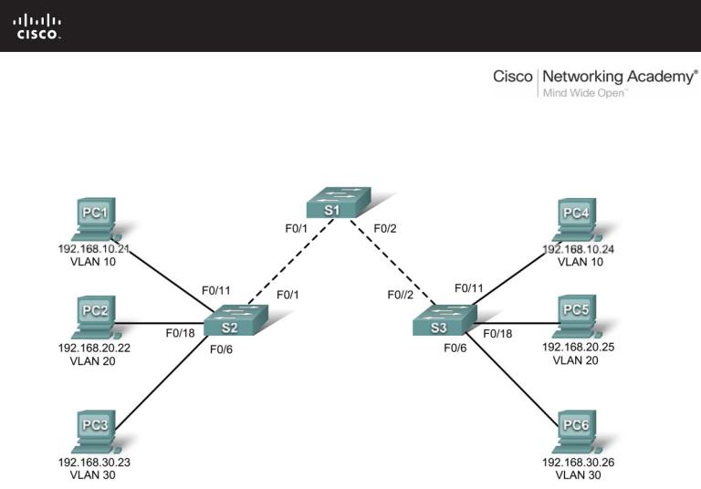
Topology Diagram
Addressing Table
|
Device |
|
|
Interface |
|
|
IP Address |
|
|
Subnet Mask |
|
|
Default Gateway |
|
|
|
|
|
|
|
|
|
|
|
|||||
|
|
|
|
|
|
|
|
|
|
|
|
|
|
|
|
S1 |
|
VLAN 56 |
192.168.56.11 |
|
255.255.255.0 |
|
|
N/A |
|||||
|
|
|
|
|
|
|
|
|
|
|||||
|
S2 |
|
VLAN 56 |
192.168.56.12 |
|
255.255.255.0 |
|
|
N/A |
|||||
|
|
|
|
|
|
|
|
|
|
|||||
|
S3 |
|
VLAN 56 |
192.168.56.13 |
|
255.255.255.0 |
|
|
N/A |
|||||
|
|
|
|
|
|
|
|
|
|
|||||
|
PC1 |
|
NIC |
192.168.10.21 |
|
255.255.255.0 |
|
192.168.10.1 |
|
|||||
|
|
|
|
|
|
|
|
|
|
|||||
|
PC2 |
|
NIC |
192.168.20.22 |
|
255.255.255.0 |
|
192.168.20.1 |
|
|||||
|
|
|
|
|
|
|
|
|
|
|||||
|
PC3 |
|
NIC |
192.168.30.23 |
|
255.255.255.0 |
|
192.168.30.1 |
|
|||||
|
|
|
|
|
|
|
|
|
|
|||||
|
PC4 |
|
NIC |
192.168.10.24 |
|
255.255.255.0 |
|
192.168.10.1 |
|
|||||
|
|
|
|
|
|
|
|
|
|
|||||
|
PC5 |
|
NIC |
192.168.20.25 |
|
255.255.255.0 |
|
192.168.20.1 |
|
|||||
|
|
|
|
|
|
|
|
|
|
|||||
|
PC6 |
|
NIC |
192.168.30.26 |
|
255.255.255.0 |
|
192.168.30.1 |
|
|||||
|
|
|
|
|
|
|
|
|
|
|
|
|
|
|
All contents are Copyright © 1992–2007 Cisco Systems, Inc. All rights reserved. This document is Cisco Public Information. |
Page 1 of 3 |

CCNA Exploration |
|
LAN Switching and Wireless: VLANs |
PT Activity 3.5.2: Challenge VLAN Configuration |
Port Assignments (Switches 2 and 3)
|
|
|
|
Ports |
Assignment |
|
Network |
|
|
|
|
Fa0/1 – 0/5 |
VLAN 56 – Management&Native |
192.168.56.0/24 |
|
|
|
|
|
Fa0/6 – 0/10 |
VLAN 30 – Guest(Default) |
192.168.30.0/24 |
|
|
|
|
|
Fa0/11 – 0/17 |
VLAN 10 – Faculty/Staff |
192.168.10.0/24 |
|
|
|
|
|
Fa0/18 – 0/24 |
VLAN 20 – Students |
192.168.20.0/24 |
|
|
|
|
|
Learning Objectives
•Perform basic configuration tasks on a switch.
•Create VLANs.
•Assign switch ports to a VLAN.
•Add, move, and change ports.
•Verify VLAN configuration.
•Enable trunking on inter-switch connections.
•Verify trunk configuration.
•Save the VLAN configuration.
Task 1: Perform Basic Switch Configurations
Configure the switches according to the following guidelines.
•Configure the switch hostname.
•Disable DNS lookup.
•Configure an encrypted privileged EXEC mode password of class.
•Configure a password of cisco for console connections.
•Configure a password of cisco for vty connections.
Task 2: Configure and Activate Ethernet Interfaces
Step 1. Configure the PCs.
From the Desktop tab, use IP Configuration to configure the Ethernet interfaces of the six PCs with the IP addresses and default gateways from the addressing table at the beginning of the activity. The IP address for PC1 will be graded as incorrect for now. You will change the PC1 address later in the activity.
Step 2. Enable the user ports for access on S2 and S3.
Task 3: Configure VLANs on the Switch
Step 1. Create VLANs on switch S1.
The VLAN IDs and names are listed in the Port Assignments table at the beginning of this activity.
All contents are Copyright © 1992–2007 Cisco Systems, Inc. All rights reserved. This document is Cisco Public Information. |
Page 2 of 3 |

CCNA Exploration |
|
LAN Switching and Wireless: VLANs |
PT Activity 3.5.2: Challenge VLAN Configuration |
Step 2. Verify that the VLANs have been created on S1.
Step 3. Configure, name, and verify VLANs on switches S2 and S3.
Step 4. Assign switch ports to VLANs on S2 and S3.
Note: The S2 Fa0/11 port will be graded incorrect for now and Packet Tracer will only grade the first port assignment for each VLAN.
Step 5. Determine which ports have been added to VLAN 10 on S2.
Step 6. Configure management VLAN 56 on each of the switches.
Step 7. Configure trunking and the native VLAN for the trunking ports on all three switches. Verify that the trunks have been configured.
Step 8. Verify that S1, S2, and S3 can communicate.
___________________________________________________________________________________
___________________________________________________________________________________
___________________________________________________________________________________
___________________________________________________________________________________
Step 9. Ping several hosts from PC2. What is the result?
___________________________________________________________________________________
___________________________________________________________________________________
___________________________________________________________________________________
___________________________________________________________________________________
Step 10. Move PC1 into the same VLAN as PC2. Can PC1 successfully ping PC2?
Step 11. Change the IP address on PC1 to 192.168.20.21. Can PC1 successfully ping PC2?
Your completion percentage should be 100%. If not, click Check Results to see which required components are not yet completed.
All contents are Copyright © 1992–2007 Cisco Systems, Inc. All rights reserved. This document is Cisco Public Information. |
Page 3 of 3 |

PT Activity 3.5.3: Troubleshooting VLAN Configurations
Topology Diagram
Addressing Table
|
Device |
|
|
Interface |
|
|
IP Address |
|
|
Subnet Mask |
|
|
Default Gateway |
|
|
|
|
|
|
|
|
|
|
|
|||||
|
|
|
|
|
|
|
|
|
|
|
|
|
|
|
|
S1 |
|
VLAN 56 |
192.168.56.11 |
|
255.255.255.0 |
|
|
N/A |
|||||
|
|
|
|
|
|
|
|
|
|
|||||
|
S2 |
|
VLAN 56 |
192.168.56.12 |
|
255.255.255.0 |
|
|
N/A |
|||||
|
|
|
|
|
|
|
|
|
|
|||||
|
S3 |
|
VLAN 56 |
192.168.56.13 |
|
255.255.255.0 |
|
|
N/A |
|||||
|
|
|
|
|
|
|
|
|
|
|||||
|
PC1 |
|
NIC |
192.168.10.21 |
|
255.255.255.0 |
|
192.168.10.1 |
|
|||||
|
|
|
|
|
|
|
|
|
|
|||||
|
PC2 |
|
NIC |
192.168.20.22 |
|
255.255.255.0 |
|
192.168.20.1 |
|
|||||
|
|
|
|
|
|
|
|
|
|
|||||
|
PC3 |
|
NIC |
192.168.20.23 |
|
255.255.255.0 |
|
192.168.30.1 |
|
|||||
|
|
|
|
|
|
|
|
|
|
|||||
|
PC4 |
|
NIC |
192.168.10.24 |
|
255.255.255.0 |
|
192.168.10.1 |
|
|||||
|
|
|
|
|
|
|
|
|
|
|||||
|
PC5 |
|
NIC |
192.168.20.25 |
|
255.255.255.0 |
|
192.168.20.1 |
|
|||||
|
|
|
|
|
|
|
|
|
|
|||||
|
PC6 |
|
NIC |
192.168.30.26 |
|
255.255.255.0 |
|
192.168.30.1 |
|
|||||
|
|
|
|
|
|
|
|
|
|
|
|
|
|
|
All contents are Copyright © 1992–2007 Cisco Systems, Inc. All rights reserved. This document is Cisco Public Information. |
Page 1 of 2 |
CCNA Exploration |
|
LAN Switching and Wireless: VLANs |
PT Activity 3.5.3: Troubleshooting VLAN Configurations |
Port Assignments (Switches 2 and 3)
|
|
|
|
Ports |
Assignment |
|
Network |
|
|
|
|
Fa0/1 – 0/5 |
VLAN 56 – Management&Native |
192.168.56.0/24 |
|
|
|
|
|
Fa0/6 – 0/10 |
VLAN 30 – Guest(Default) |
192.168.30.0/24 |
|
|
|
|
|
Fa0/11 – 0/17 |
VLAN 10 – Faculty/Staff |
192.168.10.0/24 |
|
|
|
|
|
Fa0/18 – 0/24 |
VLAN 20 – Students |
192.168.20.0/24 |
|
|
|
|
|
Learning Objectives
•Find and correct the network errors.
•Document the corrections to the network.
Introduction
In this activity, you will practice troubleshooting a misconfigured VLAN environment. The initial network has errors. Your objective is to locate and correct any and all errors in the configurations and establish end-to-end connectivity. Your final configuration should match the topology diagram and addressing table. All passwords are set to cisco, except the enable secret password, which is set to class.
Task 1: Find and Correct Network Errors
Once all errors are corrected, PCs belonging to the same VLAN should be able to ping each other. In addition, S1, S2, and S3 should be able to ping each other.
Your completion percentage should be 100%. If not, find and correct any errors.
Task 2: Document the Corrected Network
____________________________________________________________________________
____________________________________________________________________________
____________________________________________________________________________
____________________________________________________________________________
____________________________________________________________________________
____________________________________________________________________________
____________________________________________________________________________
____________________________________________________________________________
____________________________________________________________________________
____________________________________________________________________________
____________________________________________________________________________
____________________________________________________________________________
All contents are Copyright © 1992–2007 Cisco Systems, Inc. All rights reserved. This document is Cisco Public Information. |
Page 2 of 2 |