

PT Activity 3.6.1: Packet Tracer Skills Integration Challenge
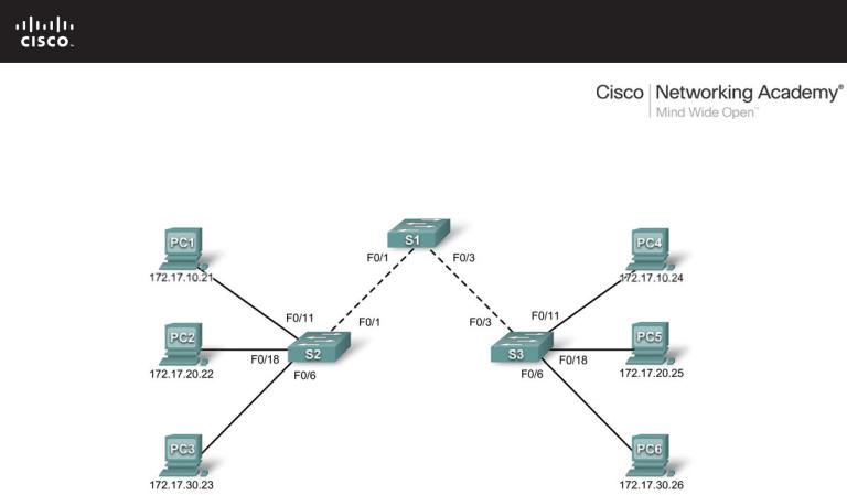
Topology Diagram
Addressing Table
Device |
Interface |
IP Address |
Subnet Mask |
Default Gateway |
|
|
|
|
|
S1 |
VLAN 99 |
172.17.99.31 |
255.255.255.0 |
172.17.99.1 |
|
|
|
|
|
S2 |
VLAN 99 |
172.17.99.32 |
255.255.255.0 |
172.17.99.1 |
|
|
|
|
|
S3 |
VLAN 99 |
172.17.99.33 |
255.255.255.0 |
172.17.99.1 |
|
|
|
|
|
PC1 |
NIC |
172.17.10.21 |
255.255.255.0 |
172.17.10.1 |
|
|
|
|
|
PC2 |
NIC |
172.17.20.22 |
255.255.255.0 |
172.17.20.1 |
|
|
|
|
|
PC3 |
NIC |
172.17.30.23 |
255.255.255.0 |
172.17.30.1 |
|
|
|
|
|
PC4 |
NIC |
172.17.10.24 |
255.255.255.0 |
172.17.10.1 |
|
|
|
|
|
PC5 |
NIC |
172.17.20.25 |
255.255.255.0 |
172.17.20.1 |
|
|
|
|
|
PC6 |
NIC |
172.17.30.26 |
255.255.255.0 |
172.17.30.1 |
|
|
|
|
|
Learning Objectives
•Add and connect switches.
•Add and connect PCs.
•Verify basic device configuration and connectivity.
•Configure and verify port security.
•Configure VLANs on the switches.
•Configure trunks on the switches.
•Verify end-to-end connectivity.
All contents are Copyright © 2007-2008 Cisco Systems, Inc. All rights reserved. This document is Cisco Public Information. |
Page 1 of 6 |

CCNA Exploration |
|
LAN Switching and Wireless: VLANs |
PT Activity 3.6.1: Packet Tracer Skills Integration Challenge |
Introduction
In this activity, you will connect and completely configure the Chapter 3 topology, including adding and connecting devices, and configuring security and VLANs.
Task 1: Add and Connect the Switches
Step 1. Add the S2 switch.
S2 must be a 2960 series switch. Change the Display Name and Hostname to S2. Names are casesensitive.
Step 2. Connect S2 to S1.
Connect S2 Fa0/1 to S1 Fa0/1.
Step 3. Check results.
Your completion percentage should be 5%. If not, click Check Results to see which required components are not yet completed.
Step 4. Add the S3 switch.
S3 must be a 2960 series switch. Change the Display Name and Hostname to S3. Names are casesensitive.
Step 4. Connect S3 to S1.
Connect S3 Fa0/3 to S1 Fa0/3.
Step 5. Check results.
Your completion percentage should be 9%. If not, click Check Results to see which required components are not yet completed.
Task 2: Add and Connect the PCs
Step 1. Add PC1, PC2, PC3, PC4, PC5, and PC6.
•Add the six PCs according to the chapter topology.
•If necessary, change the Display Name to match the names in the addressing table. Display names are case-sensitive.
Step 2. Connect PC1, PC2, and PC3 to S2.
•Connect PC1 to Fa0/11 on S2
•Connect PC2 to Fa0/18 on S2
•Connect PC3 to Fa0/6 on S2
Step 3. Connect PC4, PC5, and PC6 to S3.
•Connect PC4 to Fa0/11 on S3
•Connect PC5 to Fa0/18 on S3
•Connect PC6 to Fa0/6 on S3
All contents are Copyright © 2007-2008 Cisco Systems, Inc. All rights reserved. This document is Cisco Public Information. |
Page 2 of 6 |

CCNA Exploration |
|
LAN Switching and Wireless: VLANs |
PT Activity 3.6.1: Packet Tracer Skills Integration Challenge |
Step 4. Check results.
Your completion percentage should be 32%. If not, click Check Results to see which required components are not yet completed.
Task 3: Configure Devices and Verify Connectivity
Step 1. Configure switches with basic commands.
Configure each switch with the following basic settings.
•Hostname
•Enable secret password
•Line configurations
•Service encryption
Step 2. Configure the management VLAN interface on S1, S2, and S3.
Configure VLAN 99 as the management VLAN interface on S1, S2, and S3. This interface is not active until after trunking is configured later in the activity. However, activate the interface at this time with the appropriate command.
Step 3. Configure PC IP addressing.
Configure the PCs with IP addressing according to the addressing table.
Step 4. Verify that PCs on the same subnet can ping each other.
Switch to Simulation mode and use the Add Simple PDU tool to create pings between PCs on the same VLAN. Verify that the following PCs can ping each other:
•PC1 to PC4
•PC2 to PC5
•PC3 to PC6
Step 5. From Simulation mode, observe the broadcast traffic.
•Clear the learned MAC addresses so that the switches must broadcast ping packets.
•From Simulation mode, observe the broadcast traffic that propagates throughout the LAN until the switches learn the ports of each PC.
Step 6. Check results.
Your completion percentage should be 53%. If not, click Check Results to see which required components are not yet completed.
Task 4: Configure and Verify Port Security
Step 1. Configure access links with port security.
Normally, you configure port security on all access ports or shut down the port if it is not in use. Return to Realtime mode and use the following policy to establish port security just on the ports used by the PCs.
• Set the port to access mode. |
|
|
• |
Enable port security. |
|
• Allow only one MAC address. |
|
|
• |
Configure the first learned MAC address to “stick” to the configuration. |
|
All contents are Copyright © 2007-2008 Cisco Systems, Inc. All rights reserved. This document is Cisco Public Information. |
Page 3 of 6 |
|

CCNA Exploration |
|
LAN Switching and Wireless: VLANs |
PT Activity 3.6.1: Packet Tracer Skills Integration Challenge |
•Set the port to shut down if there is a security violation.
Force the switches to learn the MAC addresses by sending pings across all three switches
Note: Only enabling port security is graded by Packet Tracer. However, all the port security tasks listed above are required to complete this activity.
Step 2. Verify port security is active for the interfaces attached to PCs.
What command would you use to verify that port security is active on an interface?
____________________________________
Port Security |
: Enabled |
Port Status |
: Secure-up |
Violation Mode |
: Shutdown |
Aging Time |
: 0 mins |
Aging Type |
: Absolute |
SecureStatic Address Aging |
: Disabled |
Maximum MAC Addresses |
: 1 |
Total MAC Addresses |
: 1 |
Configured MAC Addresses |
: 1 |
Sticky MAC Addresses |
: 0 |
Last Source Address:Vlan |
: 0050.0F00.6668:1 |
Security Violation Count |
: 0 |
Note: The Last Source Address:Vlan information should show a MAC address. Your MAC address may be different than the one shown here. If the MAC address in this field is 0000.0000.0000, send traffic to the port by pinging across the switch to the other PC on the same subnet.
Step 3. Test port security.
•Connect PC2 to the port of PC3, and connect PC3 to the port of PC2.
•Send pings between PCs on the same subnet.
•The ports for PC2 and PC3 should shut down.
Step 4. Verify that ports are err-disabled and that a security violation has been logged.
What command shows the following output?
________________________________________
FastEthernet0/6 is down, line protocol is down (err-disabled) Hardware is Lance, address is 000a.41e8.c906 (bia 000a.41e8.c906)
<output omitted>
What command shows the following output?
____________________________________
Port Security |
: Enabled |
Port Status |
: Secure-shutdown |
Violation Mode |
: Shutdown |
Aging Time |
: 0 mins |
Aging Type |
: Absolute |
SecureStatic Address Aging |
: Disabled |
Maximum MAC Addresses |
: 1 |
Total MAC Addresses |
: 1 |
Configured MAC Addresses |
: 1 |
Sticky MAC Addresses |
: 0 |
All contents are Copyright © 2007-2008 Cisco Systems, Inc. All rights reserved. This document is Cisco Public Information. Page 4 of 6

CCNA Exploration |
|
LAN Switching and Wireless: VLANs |
PT Activity 3.6.1: Packet Tracer Skills Integration Challenge |
Last Source Address:Vlan |
: |
0050.0F00.6668:1 |
Security Violation Count |
: |
1 |
Step 5. Reconnect PCs to the correct port and clear port security violations.
•Connect PC2 and PC3 back to the correct port.
•Clear the port security violation.
•Verify that PC2 and PC3 can send pings across S2.
Step 6. Check results.
Your completion percentage should be 75%. If not, click Check Results to see which required components are not yet completed.
Task 5: Configure VLANs on the Switches
Step 1. Create and name the VLANs.
Create and name the following VLANs on the switches S1, S2, and S3:
•VLAN 10, name = Faculty/Staff
•VLAN 20, name = Students
•VLAN 30, name = Guest(Default)
•VLAN 99, name = Management&Native
•VLAN 10: PC1 and PC4
•VLAN 20: PC2 and PC5
•VLAN 30: PC3 and PC6
Page 5 of 6

CCNA Exploration |
|
LAN Switching and Wireless: VLANs |
PT Activity 3.6.1: Packet Tracer Skills Integration Challenge |
Task 6: Configure Trunks on the Switches
Step 1. Configure trunking on the appropriate interfaces.
•Configure trunking on the appropriate interfaces on switch S1.
•Verify that switches S2 and S3 are now in trunking mode.
•Manually configure the appropriate interfaces on S2 and S3 for trunking.
•Configure VLAN 99 as the native VLAN for all trunks.
Step 2. Test connectivity
After the switch trunk ports transition to the forwarding state (green link lights), you should be able to successfully ping between PCs on the same VLAN.
Step 3. Check results.
Your completion percentage should be 100%. If not, click Check Results to see which required components are not yet completed.
All contents are Copyright © 2007-2008 Cisco Systems, Inc. All rights reserved. This document is Cisco Public Information. |
Page 6 of 6 |