


PT Activity 1.4.1: Packet Tracer Skills Integration Challenge
Topology Diagram
Addressing Table
|
Device |
|
|
Interface |
|
|
IP Address |
|
|
Subnet Mask |
|
Default Gateway |
|
|
|
|
|
|
|
|
|||||
|
|
|
|
|
|
|
|
|
|
|
|
|
|
R1 |
|
Fa0/0 |
|
|
|
|
|
|
N/A |
||
|
|
|
|
|
|
|
|
|
|
|
||
|
|
Fa0/1 |
|
|
|
|
|
|
N/A |
|||
|
|
|
|
|
|
|
|
|
|
|||
|
|
|
|
|
|
|
|
|
|
|
||
|
PC1 |
|
NIC |
|
|
|
|
|
|
|
||
|
|
|
|
|
|
|
|
|
|
|
||
|
PC2 |
|
NIC |
|
|
|
|
|
|
|
||
|
|
|
|
|
|
|
|
|
|
|
||
|
Laser |
|
NIC |
|
|
|
|
|
|
|
||
|
|
|
|
|
|
|
|
|
|
|
||
|
Server |
|
NIC |
|
|
|
|
|
|
|
||
|
|
|
|
|
|
|
|
|
|
|
|
|
Learning Objectives
•Design the network.
•Build the network.
•Apply a basic configuration.
•Test connectivity.
Introduction
This activity reviews the skills you acquired in the Exploration: Network Fundamentals course. The skills include subnetting, building a network, applying an addressing scheme, and testing connectivity. You should review those skills before proceeding. In addition, this activity reviews the basics of using the Packet Tracer program. Packet Tracer is integrated throughout this course. You must know how to
All contents are Copyright © 1992–2007 Cisco Systems, Inc. All rights reserved. This document is Cisco Public Information. |
Page 1 of 3 |

CCNA Exploration |
PT Activity 1.4.1: Packet Tracer Skills Integration Challenge |
LAN Switching and Wireless: LAN Design |
navigate the Packet Tracer environment to complete this course. Use the tutorials if you need a review of Packet Tracer fundamentals. The tutorials are located in the Packet Tracer Help menu.
Task 1: Design and Document an Addressing Scheme
Step 1. Design an addressing scheme.
Using the 192.168.1.0/24 address space, design an addressing scheme according to the following requirements:
Subnet A
•Subnet the address space to provide for 100 hosts.
•Assign the Fa0/0 interface the first useable IP address.
•Assign PC1 the second useable IP address.
•Assign PC2 the last useable IP address in the subnet.
Subnet B
•Subnet the remaining address space to provide for 50 hosts.
•Assign the Fa0/1 interface the first useable IP address.
•Assign the laser printer the second useable IP address.
•Assign the server the last useable IP address in the subnet.
Step 2. Document the addressing scheme.
Complete an addressing table for the router and each end device in the network.
Task 2: Add and Connect the Devices
Step 1. Add the necessary equipment.
Add the following devices to the network. For placement of these devices, refer to the topology diagram.
•Two 2960-24TT switches
•One 1841 router
•Two generic PCs
•One generic server
•One generic printer
Step 2. Name the devices.
Change the Display Name and Hostname to match the device names shown in the topology diagram. Device names are case-sensitive.
Step 3. Connect the devices.
Use the following specifications for the connections between the devices:
•S1 Fa0/1 to R1 Fa0/0
•S1 Fa0/6 to PC1
•S1 Fa0/12 to PC2
•S2 Fa0/1 to R1 Fa0/1
All contents are Copyright © 1992–2007 Cisco Systems, Inc. All rights reserved. This document is Cisco Public Information. |
Page 2 of 3 |

CCNA Exploration |
PT Activity 1.4.1: Packet Tracer Skills Integration Challenge |
LAN Switching and Wireless: LAN Design |
•S2 Fa0/6 to Laser
•S2 Fa0/12 to Server
Step 4. Check results.
Your completion percentage should be 52%. If not, click Check Results to see which required components are not yet completed.
Task 3: Apply Basic Configurations
Step 1. Configure the router.
•The privileged EXEC secret password is class.
•The banner is Authorized Access Only.
•The line password is cisco for console and telnet.
•Configure the appropriate interfaces. Use the following descriptions:
Link to PC LAN
Link to Server & Printer
Note: Remember that the banner and descriptions are case-sensitive. Do not forget to activate the interfaces.
Step 2. Configure the end devices.
Step 3. Check results.
Your completion percentage should be 100%. If not, click Check Results to see which required components are not yet completed.
Task 4: Test Connectivity and Examine the Configuration
You should now have end-to-end connectivity, which means every end device should be reachable from any other end device. From PC1 and PC2, ping all end devices on the network. If you get an error, try pinging again to make sure ARP tables are updated. If you still receive an error, check your subnetting, the cables, and the IP addresses. Isolate problems and implement solutions.
All contents are Copyright © 1992–2007 Cisco Systems, Inc. All rights reserved. This document is Cisco Public Information. |
Page 3 of 3 |
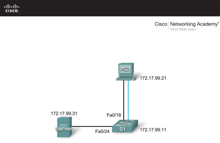
PT Activity 2.3.8: Configuring Basic Switch Management
Topology Diagram
Addressing Table
|
Device |
|
|
Interface |
|
|
IP Address |
|
|
Subnet Mask |
|
|
|
|
|
|
|
|
|
||||
|
|
|
|
|
|
|
|
|
|
|
|
|
S1 |
|
VLAN99 |
172.17.99.11 |
|
255.255.255.0 |
|
||||
|
|
|
|
|
|
|
|
||||
|
PC1 |
|
NIC |
172.17.99.21 |
|
255.255.255.0 |
|
||||
|
|
|
|
|
|
|
|
||||
|
Server |
|
NIC |
172.17.99.31 |
|
255.255.255.0 |
|
||||
|
|
|
|
|
|
|
|
|
|
|
|
Learning Objectives
•Connect to the switch using a console connection.
•Navigate through various CLI modes.
•Use the Help Facility to configure the clock.
•Access and configure command history.
•Configure the boot sequence.
•Configure a PC and connect it to a switch.
•Configure full duplex.
•Manage the MAC address table.
•Manage the switch configuration file.
Introduction
Basic switch management is the foundation for configuring switches. This activity focuses on navigating command-line interface modes, using help functions, accessing the command history, configuring boot
All contents are Copyright © 1992–2007 Cisco Systems, Inc. All rights reserved. This document is Cisco Public Information. |
Page 1 of 7 |

CCNA Exploration |
|
LAN Switching and Wireless: Basic Switch Concepts and Configuration |
PT Activity 2.3.8: Configuring Basic Switch Management |
sequence parameters, setting speed and duplex settings, as well as managing the MAC address table and switch configuration file. Skills learned in this activity are necessary for configuring basic switch security in later chapters.
Task 1: Connect to the Switch
Step 1: Connect S1 and PC1.
•Using a console cable, connect the RS 232 interface on PC1 to the console interface on switch S1.
•Click PC1 and then click the Desktop tab. Select Terminal in the Desktop tab.
•Keep these default settings for Terminal Configuration and then click OK:
Bits Per Second = 9600 Data Bits = 8
Parity = None Stop Bits = 1
Flow Control = None
•You are now consoled into S1. Press Enter to get the Switch prompt.
Step 2: Check results.
Your completion percentage should be 6%. If not, click Check Results to see which required components are not yet completed.
Task 2: Navigate Through CLI Modes
Step 1: In user EXEC mode, type ? and note the list of available commands.
While in user EXEC mode, the available commands are limited to basic monitoring commands.
Step 2: Use the enable command to go to privileged EXEC mode.
Switch>enable
Switch#
The prompt changes from > to #.
Step 3: In privileged EXEC mode, type ? and note the list of available commands.
There are now more available commands compared to user EXEC mode. In addition to the basic monitoring commands, configuration and management commands can now be accessed.
Step 4: Change to global configuration mode.
Switch#configure terminal
Switch(config)#
Step 5: In global configuration mode, type ? and note the list of available commands.
Step 6: Configure S1 as the hostname.
Switch(config)#hostname S1 S1(config)#
All contents are Copyright © 1992–2007 Cisco Systems, Inc. All rights reserved. This document is Cisco Public Information. |
Page 2 of 7 |
CCNA Exploration |
|
LAN Switching and Wireless: Basic Switch Concepts and Configuration |
PT Activity 2.3.8: Configuring Basic Switch Management |
Step 7: Change to interface configuration mode for VLAN99.
The interface vlan 99 command creates the interface and changes to interface configuration mode for VLAN99.
S1(config)#interface vlan 99
S1(config-if)#
Step 8: Configure VLAN99 with 172.17.99.11/24 and activate the interface.
Use the ip address and no shutdown commands to assign the correct IP address/subnet mask and activate the interface.
S1(config-if)#ip address 172.17.99.11 255.255.255.0
S1(config-if)#no shutdown
Step 9: Change to interface configuration mode for Fa0/18.
S1(config-if)#interface fa0/18
S1(config-if)#
Step 10: Set the port mode to access.
To allow for frames to be sent and received from the interface, change the switching mode to access using the switchport mode access command.
S1(config-if)#switchport mode access
Step 11: Assign VLAN99 to the port.
To allow the Fa0/18 interface to act as a member of VLAN 99, issue the switchport access vlan 99 command.
S1(config-if)#switchport access vlan 99
Step 12: Exit interface configuration mode.
Issue the exit command to leave interface configuration mode and enter global configuration mode.
Step 13: Enter configuration mode for the console line.
S1(config)#line console 0
S1(config-line)#
Step 14: In line configuration mode, type ? and note the list of available commands.
Step 15: Enter cisco as the password and require users to login.
S1(config-line)#password cisco S1(config-line)#login
Step 16: Return to privileged EXEC mode using the end command.
S1(config-line)#end
S1#
Step 17: Check results.
Your completion percentage should be 31%. If not, click Check Results to see which required components are not yet completed.
All contents are Copyright © 1992–2007 Cisco Systems, Inc. All rights reserved. This document is Cisco Public Information. |
Page 3 of 7 |

CCNA Exploration |
|
LAN Switching and Wireless: Basic Switch Concepts and Configuration |
PT Activity 2.3.8: Configuring Basic Switch Management |
Task 3: Use Help Facility to Configure the Clock
Step 1: At the privileged EXEC command prompt, type clock ?.
S1#clock ?
The only option is set.
Step 2: Use Help to assist setting the clock to the current time.
S1#clock ?
set Set the time and date
S1#clock set ? hh:mm:ss Current Time
S1#clock set 12:12:12 ?
<1-31> |
Day of the month |
MONTH |
Month of the year |
Continue issuing the ? command until you have completed configuring the clock. You are warned with a % Incomplete command message if the clock command is not fully entered with all the required arguments.
Step 3: Verify that the clock is set.
To verify that the clock is set, issue the show clock command.
Note: Packet Tracer does not always show the correct time configured.
Completion is still at 31% at the end of this Task.
Task 4: Access and Configure Command History
Step 1: View the most recent commands entered.
Issue the show history command. Remember how many commands are listed.
S1#show history
Step 2: Change the number of commands stored in the history buffer.
Enter line configuration mode for both the console and Telnet lines. Set the number of commands held in the history buffer to 35.
S1(config)#line console 0
S1(config-line)#history size 35
S1(config-line)#line vty 0 4
S1(config-line)#history size 35
Step 3: Verify that the size of the history buffer has changed.
Return to privileged EXEC mode and issue the show history command again. There should be more commands displayed than previously.
Step 4: Check results.
Your completion percentage should be 50%. If not, click Check Results to see which required components are not yet completed.
All contents are Copyright © 1992–2007 Cisco Systems, Inc. All rights reserved. This document is Cisco Public Information. |
Page 4 of 7 |

CCNA Exploration |
|
LAN Switching and Wireless: Basic Switch Concepts and Configuration |
PT Activity 2.3.8: Configuring Basic Switch Management |
Task 5: Configure the Boot Sequence
Step 1: Check which Cisco IOS software version is currently loaded.
S1#show version
Cisco IOS Software, C2960 Software (C2960-LANBASE-M), Version 12.2(25)FX, RELEASE SOFTWARE (fc1)
Copyright (c) 1986-2005 by Cisco Systems, Inc. Compiled Wed 12-Oct-05 22:05 by pt_team <output omitted>
The version is listed in the first line.
Step 2: Check which Cisco IOS images are loaded in flash memory.
S1#show flash
Directory of flash:/
3 |
-rw- |
4414921 |
<no date> |
c2960-lanbase-mz.122-25.FX.bin |
2 |
-rw- |
4670455 |
<no date> |
c2960-lanbase-mz.122-25.SEE1.bin |
6 |
-rw- |
616 |
<no date> |
vlan.dat |
32514048 bytes total (23428056 bytes free) S1#
Note that there are two versions in flash memory. The version that is currently loaded is c2960-lanbase- mz.122-25.FX.bin.
Step 3: Configure the system to boot using a different Cisco IOS image.
In global configuration mode, issue this command.
S1(config)#boot system flash:c2960-lanbase-mz.122-25.SEE1.bin
Note: Although you can enter this command in Packet Tracer, the switch still loads the first image listed in flash.
In this lab, Packet Tracer does not grade the boot system command, so completion remains at 50% at the end of this task.
Task 6: Configure a PC and Connect it to a Switch
Step 1: Configure PC1 with the IP address/subnet mask 172.17.99.21/24.
•Exit the terminal to return to the Desktop tab.
•Click IP Configuration and set the IP address to 172.17.99.21 and subnet mask to 255.255.255.0.
Step 2: Connect PC1 to Fa0/18 on the switch.
Using the copper straight-through cable, connect the FastEthernet port of the PC to the Fa0/18 port on the switch.
Step 3: Test connectivity between S1 and PC1.
Ping between S1 and PC1. It may take a few attempts, but it should be successful.
All contents are Copyright © 1992–2007 Cisco Systems, Inc. All rights reserved. This document is Cisco Public Information. |
Page 5 of 7 |

CCNA Exploration |
|
LAN Switching and Wireless: Basic Switch Concepts and Configuration |
PT Activity 2.3.8: Configuring Basic Switch Management |
Step 4: Check results.
Your completion percentage should be 69%. If not, click Check Results to see which required components are not yet completed.
Task 7: Configure Duplex and Speed
Step 1: Use the Config tab change the settings.
On PC1, select the Config tab. Set the bandwidth of the FastEthernet interface to 100 Mbps and Full Duplex.
Step 2: Use Cisco IOS commands to set Fa0/18.
Return to the desktop and select Terminal, and then configure the interface.
S1(config)#interface fa0/18
S1(config-if)#duplex full
S1(config-if)#speed 100
Step 3: Test connectivity between S1 and PC1.
Issue a ping from S1 to PC1. It may take a few attempts, but it should be successful.
Step 4: Check results.
Your completion percentage should be 81%. If not, click Check Results to see which required components are not yet completed.
Task 8: Manage the MAC Address Table
Step 1: Check the MAC address of the server.
Click the Server, then the Config tab, and then FastEthernet. The MAC Address is 0060.3EDD.19A3.
Step 2: Configure static MAC for the TFTP server.
By configuring a static MAC for the TFTP server, the switch always knows which port to use to send out traffic destined for the server. In global configuration mode on S1, add the MAC address to the addressing table of the switch:
S1(config)#mac-address-table static 0060.3EDD.19A3 vlan 99 int fa0/24
Step 3: Verify that the static MAC address is now in the MAC address table.
S1#show mac-address-table
Mac Address Table
-------------------------------------------
Vlan |
Mac Address |
Type |
Ports |
---- |
----------- |
-------- |
----- |
99 |
0060.3edd.19a3 |
STATIC |
Fa0/24 |
99 |
0060.5c5b.cd23 |
DYNAMIC |
Fa0/18 |
S1# |
|
|
|
Notice how the MAC address from PC1 was added dynamically. This entry may or may not be in your table depending on how long it has been since you pinged from PC1 to S1.
All contents are Copyright © 1992–2007 Cisco Systems, Inc. All rights reserved. This document is Cisco Public Information. |
Page 6 of 7 |

CCNA Exploration |
|
LAN Switching and Wireless: Basic Switch Concepts and Configuration |
PT Activity 2.3.8: Configuring Basic Switch Management |
Step 4: Test connectivity between S1 and PC1.
Issue a ping from S1 to PC1. It may take a few attempts, but the command should be successful.
Packet Tracer does not grade this command. This command is needed to allow the switch to know where to send traffic destined for the server. Completion is still at 81% at the end of this task.
Task 9: Manage the Switch Configuration File
Using a copper straight-through cable, connect the FastEthernet port on the server to the Fa0/24 port on the switch.
Step 1: Enter interface configuration mode for Fa0/24.
S1#configure terminal
S1(config)#interface fa0/24
S1(config-if)#
Step 2: Set the port mode to access.
Setting the port mode to access allows frames to be sent and received from the interface.
S1(config-if)#switchport mode access
Note: Packet Tracer does not grade the switchport mode access command. However, the command is needed to change the interface from its default mode to access mode.
Step 3: Assign VLAN99 to the port.
Assigning VLAN99 to the port allows the Fa0/24 interface to act as a member of VLAN 99.
S1(config-if)#switchport access vlan 99
Step 4: Verify S1 can ping the server.
Ping the server from S1. It may take a few attempts, but it should be successful.
Step 5: Back up the startup configuration to the server.
In privileged EXEC mode, copy the startup configuration to the sever. When you are prompted for the address of the remote host, enter IP address of the server, 172.17.99.31. For the destination filename, use the default filename by pressing Enter.
S1#copy startup-config tftp:
Address or name of remote host []? 172.17.99.31
Destination filename [S1-confg]? [Enter]
Step 6: Verify that the server has the startup configuration.
To determine if the startup configuration was successfully transferred to the server, click the server and then click the Config tab. The S1-confg file should be listed under Services and TFTP.
Note: Restoring the startup from the server is not fully simulated in Packet Tracer.
Step 7: Check results.
Your completion percentage should be 100%. If not, click Check Results to see which required components are not yet completed.
All contents are Copyright © 1992–2007 Cisco Systems, Inc. All rights reserved. This document is Cisco Public Information. |
Page 7 of 7 |