

PT Activity 7.5.3: Troubleshooting Wireless WRT300N 
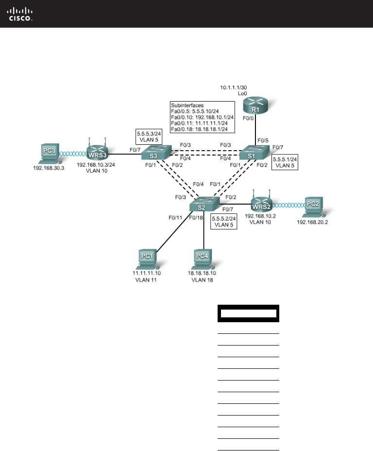
Topology Diagram
Addressing Table
|
|
|
|
|
|
|
|
|
|
|
|
Device |
|
Interface |
IP Address |
|
|
Subnet Mask |
|
|
Default Gateway |
|
|
|
|
|
|
|
|
|
|
|
|
|
|
Fa0/0.5 |
5.5.5.10 |
|
255.255.255.0 |
|
|
N/A |
|
|
|
|
|
|
|
|
|
|
|
|
|
|
|
Fa0/0.10 |
192.168.10.1 |
|
255.255.255.0 |
|
|
N/A |
|
|
R1 |
|
|
|
|
|
|
|
|
|
|
|
Fa0/0.11 |
11.11.11.1 |
|
255.255.255.0 |
|
|
N/A |
||
|
|
|
|
|
|
|
|
|
|
|
|
|
|
Fa0/0.18 |
18.18.18.1 |
|
255.255.255.0 |
|
|
N/A |
|
|
|
|
|
|
|
|
|
|
|
|
|
|
|
Lo0 |
10.1.1.1 |
|
255.255.255.252 |
|
|
N/A |
|
|
|
|
|
|
|
|
|
|
|
|
|
WRS2 |
|
WAN |
192.168.10.2 |
|
255.255.255.0 |
|
|
192.168.10.1 |
|
|
|
|
|
|
|
|
|
|
|
|
|
|
LAN/Wireless |
192.168.20.1 |
|
255.255.255.0 |
|
|
N/A |
||
|
|
|
|
|
|
|||||
|
|
|
|
|
|
|
|
|
|
|
|
WRS3 |
|
WAN |
192.168.10.3 |
|
255.255.255.0 |
|
|
192.168.10.1 |
|
|
|
|
|
|
|
|
|
|
|
|
|
|
LAN/Wireless |
192.168.30.1 |
|
255.255.255.0 |
|
|
N/A |
||
|
|
|
|
|
|
|||||
|
|
|
|
|
|
|
|
|
|
|
|
PC1 |
|
NIC |
11.11.11.10 |
|
255.255.255.0 |
|
|
11.11.11.1 |
|
|
|
|
|
|
|
|
|
|
|
|
|
PC4 |
|
NIC |
18.18.18.10 |
|
255.255.255.0 |
|
|
18.18.18.1 |
|
|
|
|
|
|
|
|
|
|
|
|
|
Addressing Table |
continued on next page |
|
|
|
|
|
|
|
|
|
All contents are Copyright © 1992–2007 Cisco Systems, Inc. All rights reserved. This document is Cisco Public Information. |
Page 1 of 2 |
||||||||

CCNA Exploration |
|
LAN Switching and Wireless: Basic Wireless Concepts and Configuration |
PT Activity 7.5.3: Challenge Wireless WRT300N |
Addressing Table continued |
|
|
|
|
|
|
|
|
|
S1 |
VLAN 5 |
5.5.5.1 |
255.255.255.0 |
N/A |
|
|
|
|
|
S2 |
VLAN 5 |
5.5.5.2 |
255.255.255.0 |
N/A |
|
|
|
|
|
S3 |
VLAN 5 |
5.5.5.3 |
255.255.255.0 |
N/A |
|
|
|
|
|
Learning Objectives
•Troubleshoot the network.
•Verify connectivity.
Scenario
In this activity, a basic network and wireless network have been configured improperly. You must find and correct the misconfigurations based on the minimum network specifications provided by your company.
Task 1: Troubleshoot the Network
Examine the routers and switches; determine any errors in the network.
Note: Packet Tracer will not grade the allowed VLANs for trunking mode.
The wireless routing requirements are as follows:
•Connections via the IP addresses shown in the topology diagram.
•30 clients can get an IP address through DHCP at a single time.
•Wireless clients must be authenticated using WEP with a key of 5655545251.
•Ping requests coming from outside WAN ports of the Linksys routers to their inside LAN/wireless IP addresses (192.168.30.1) must be successful.
•DHCP must assign PC2 and PC3 their proper IP addresses.
Task 2: Verify Connectivity
Due to a bug, Packet Tracer does not allow for PC2 and PC3 to ping one another, however connectivity should exist in all other circumstances. If they do not, continue troubleshooting. All the PCs should be able to ping one another and R1. Your completion result should be 100%. If not, continue troubleshooting.
All contents are Copyright © 1992–2007 Cisco Systems, Inc. All rights reserved. This document is Cisco Public Information. |
Page 2 of 2 |
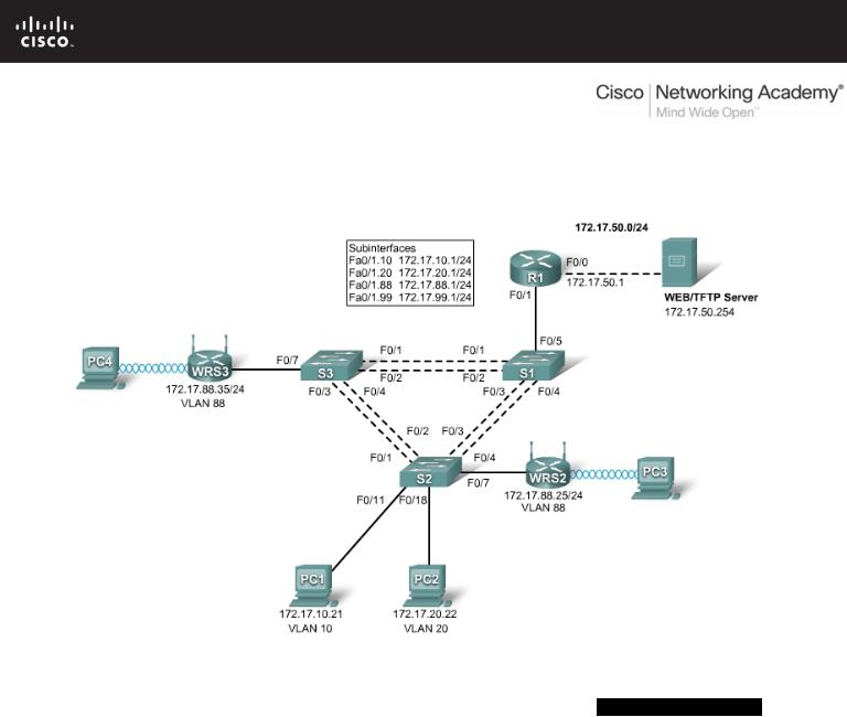
PT Activity 7.6.1: Packet Tracer Skills Integration Challenge
Topology Diagram
Addressing Table
|
Device |
|
|
Interface |
|
|
IP Address |
|
|
Subnet Mask |
|
Default Gateway |
|
|
|
|
|
|
|
|
|||||
|
|
|
|
|
|
|
|
|
|
|
|
|
|
|
|
|
Fa0/0 |
172.17.50.1 |
|
255.255.255.0 |
|
N/A |
|||
|
|
|
|
|
|
|
|
|
|
|||
|
|
|
|
Fa0/1.10 |
172.17.10.1 |
|
255.255.255.0 |
|
N/A |
|||
|
R1 |
|
|
|
|
|
|
|
||||
|
|
Fa0/1.20 |
172.17.20.1 |
|
255.255.255.0 |
|
N/A |
|||||
|
|
|
|
|
|
|
|
|
|
|||
|
|
|
|
Fa0/1.88 |
172.17.88.1 |
|
255.255.255.0 |
|
N/A |
|||
|
|
|
|
|
|
|
|
|
|
|||
|
|
|
|
Fa0/1.99 |
172.17.99.1 |
|
255.255.255.0 |
|
N/A |
|||
|
|
|
|
|
|
|
|
|
|
|||
|
WRS2 |
|
Internet |
172.17.88.25 |
|
255.255.255.0 |
|
172.17.88.1 |
||||
|
|
|
|
|
|
|
|
|
|
|
||
|
|
LAN |
172.17.40.1 |
|
255.255.255.0 |
|
N/A |
|||||
|
|
|
|
|
|
|||||||
|
|
|
|
|
|
|
|
|
|
|||
|
WRS3 |
|
Internet |
172.17.88.35 |
|
255.255.255.0 |
|
172.17.88.1 |
||||
|
|
|
|
|
|
|
|
|
|
|
||
|
|
LAN |
172.17.30.1 |
|
255.255.255.0 |
|
N/A |
|||||
|
|
|
|
|
|
|||||||
|
|
|
|
|
|
|
|
|
|
|
|
|
Addressing Table continued on the next page
All contents are Copyright © 1992–2007 Cisco Systems, Inc. All rights reserved. This document is Cisco Public Information. |
Page 1 of 5 |

CCNA Exploration
LAN Switching and Wireless: Basic Wireless Concepts and Configuratio PT Activity 7.6.1: Packet Tracer Skills Integration Challenge
Addressing Table continued
S1 |
VLAN 99 |
172.17.99.31 |
255.255.255.0 |
172.17.99.1 |
|
|
|
|
|
S2 |
VLAN 99 |
172.17.99.32 |
255.255.255.0 |
172.17.99.1 |
|
|
|
|
|
S3 |
VLAN 99 |
172.17.99.33 |
255.255.255.0 |
172.17.99.1 |
|
|
|
|
|
PC1 |
NIC |
172.17.10.21 |
255.255.255.0 |
172.17.10.1 |
|
|
|
|
|
PC2 |
NIC |
172.17.20.22 |
255.255.255.0 |
172.17.20.1 |
|
|
|
|
|
Learning Objectives
•Configure and verify basic device configurations.
•Configure VTP.
•Configure trunking.
•Configure VLANs.
•Assign VLAN to ports.
•Configure STP.
•Configure router-on-a-stick inter-VLAN routing.
•Configure wireless connectivity.
•Verify end-to-end connectivity.
Introduction
In this final Packet Tracer Skills Integration Challenge activity for the Exploration: LAN Switching and Wireless course, you will apply all the skills you have learned including configuring VLANs and VTP, optimizing STP, enabling inter-VLAN routing and integrating wireless connectivity.
Task 1: Configure and Verify Basic Device Configurations
Step 1. Configure basic commands.
Configure each switch with the following basic commands. Packet Tracer only grades the hostnames and default gateways.
•Hostnames
•Banner
•Enable secret password
•Line configurations
•Service encryption
•Switch default gateways
Step 2. Configure the management VLAN interface on S1, S2, and S3.
Create and enable interface VLAN 99 on each switch. Use the addressing table for address configuration.
Step 3. Check results.
Your completion percentage should be 13%. If not, click Check Results to see which required components are not yet completed.
Task 2: Configure VTP
All contents are Copyright © 1992–2007 Cisco Systems, Inc. All rights reserved. This document is Cisco Public Information. |
Page 2 of 5 |
CCNA Exploration
LAN Switching and Wireless: Basic Wireless Concepts and Configuratio PT Activity 7.6.1: Packet Tracer Skills Integration Challenge
Step 1. Configure the VTP mode on all three switches.
Configure S1 as the server. Configure S2 and S3 as clients.
Step 2. Configure the VTP domain name on all three switches.
Use CCNA as the VTP domain name.
Step 3. Configure the VTP domain password on all three switches.
Use cisco as the VTP domain password.
Step 4. Check results.
Your completion percentage should be 21%. If not, click Check Results to see which required components are not yet completed.
Task 3: Configure Trunking
Step 1. Configure trunking on S1, S2, and S3.
Configure the appropriate interfaces as trunks and assign VLAN 99 as the native VLAN.
Step 2. Check results.
Your completion percentage should be 44%. If not, click Check Results to see which required components are not yet completed.
Task 4: Configure VLANs
Step 1. Create the VLANs on S1.
Create and name the following VLANs on S1 only. VTP advertises the new VLANs to S2 and S3.
•VLAN 10 Faculty/Staff
•VLAN 20 Students
•VLAN 88 Wireless(Guest)
•VLAN 99 Management&Default
Step 2. Verify that VLANs have been sent to S2 and S3.
Use the appropriate commands to verify that S2 and S3 now have the VLANs you created on S1. It may take a few minutes for Packet Tracer to simulate the VTP advertisements.
Step 3. Check results.
Your completion percentage should be 54%. If not, click Check Results to see which required components are not yet completed.
Task 5: Assign VLANs to Ports
Step 1. Assign VLANs to access ports on S2 and S3.
Assign the PC access ports to VLANs:
•VLAN 10: PC1
•VLAN 20: PC2
All contents are Copyright © 1992–2007 Cisco Systems, Inc. All rights reserved. This document is Cisco Public Information. |
Page 3 of 5 |

CCNA Exploration
LAN Switching and Wireless: Basic Wireless Concepts and Configuratio PT Activity 7.6.1: Packet Tracer Skills Integration Challenge
Assign the wireless router access ports to VLAN 88.
Step 2. Verify VLAN implementation.
Use the appropriate commands to verify your VLAN implementation.
Step 3. Check results.
Your completion percentage should be 61%. If not, click Check Results to see which required components are not yet completed.
Task 6: Configure STP
Step 1. Ensure that S1 is the root bridge for all spanning tree instances.
Use 4096 priority.
Step 2. Verify that S1 is the root bridge.
Step 3. Check results.
Your completion percentage should be 66%. If not, click Check Results to see which required components are not yet completed.
Task 7: Configure Router-on-a-Stick Inter-VLAN Routing
Step 1. Configure subinterfaces.
Configure the Fa0/1 subinterfaces on R1 using the information from the addressing table.
Step 2. Check results.
Your completion percentage should be 79%. If not, click Check Results to see which required components are not yet completed.
Task 8: Configure Wireless Connectivity
Step 1. Configure IP Addressing for WRS2 and WRS3.
Configure LAN settings and then static addressing on the Internet interfaces for both WRS2 and WRS3 using the addresses from the topology.
Note: A bug in Packet Tracer may prevent you from assigning the static IP address first. A workaround for this issue is to configure the LAN settings first under Network Setup. Save the settings. Then configure the static IP information under Internet Connection Type and save settings again.
Step 2. Configure wireless network settings.
•The SSIDs for the routers are WRS2_LAN and WRS3_LAN, respectively.
•The WEP for both is 12345ABCDE.
Step 3. Configure the wireless routers for remote access.
Configure the administration password as cisco123.
Step 4. Configure PC3 and PC4 to access the network using DHCP.
PC3 connects to the WRS2_LAN, and PC4 connects to the WRS3_LAN.
All contents are Copyright © 1992–2007 Cisco Systems, Inc. All rights reserved. This document is Cisco Public Information. |
Page 4 of 5 |

CCNA Exploration
LAN Switching and Wireless: Basic Wireless Concepts and Configuratio PT Activity 7.6.1: Packet Tracer Skills Integration Challenge
Step 5. Verify remote access capability.
Step 6. Check results.
Your completion percentage should be 100%. If not, click Check Results to see which required components are not yet completed.
Task 9: Verify End-to-End Connectivity
Step 1. Verify that PC1 and Web/TFTP Server can ping each other.
Step 2. Verify that PC1 and PC2 can ping each other.
Step 3. Verify that PC3 and PC1 can ping each other.
Step 4. Verify that PC2 and PC3 can ping each other.
All contents are Copyright © 1992–2007 Cisco Systems, Inc. All rights reserved. This document is Cisco Public Information. |
Page 5 of 5 |