

PT Activity 6.4.3: Troubleshooting Inter-VLAN Routing
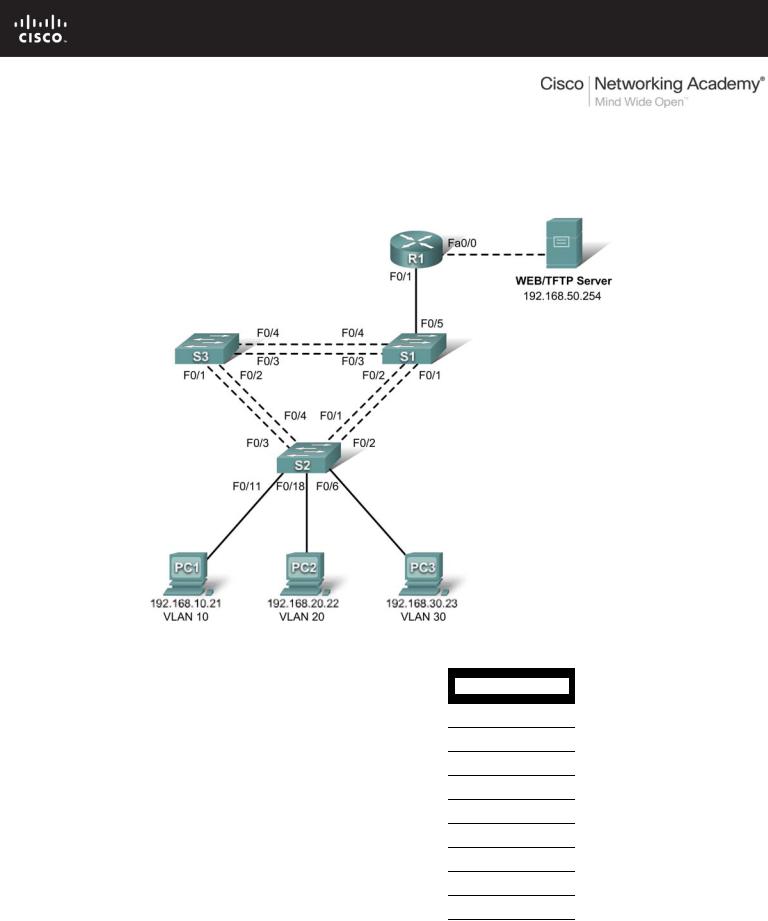
Topology Diagram
Addressing Table
|
|
|
|
|
|
|
|
|
|
|
|
Device |
|
Interface |
|
IP Address |
|
Subnet Mask |
|
|
Default Gateway |
|
|
|
|
|
|
|
|
|||
|
S1 |
|
VLAN 99 |
192.168.99.11 |
255.255.255.0 |
|
192.168.99.1 |
|||
|
|
|
|
|
|
|
|
|||
|
S2 |
|
VLAN 99 |
192.168.99.12 |
255.255.255.0 |
|
192.168.99.1 |
|||
|
|
|
|
|
|
|
|
|||
|
S3 |
|
VLAN 99 |
192.168.99.13 |
255.255.255.0 |
|
192.168.99.1 |
|||
|
|
|
|
|
|
|
|
|
||
|
R1 |
|
Fa0/0 |
192.168.50.1 |
255.255.255.0 |
|
|
N/A |
||
|
|
|
|
|
|
|
|
|
|
|
|
|
Fa0/1 |
|
See Interface Configuration Table |
|
|
N/A |
|||
|
|
|
|
|
|
|||||
|
|
|
|
|
|
|
|
|||
|
PC1 |
|
NIC |
192.168.10.21 |
255.255.255.0 |
|
192.168.10.1 |
|||
|
|
|
|
|
|
|
|
|||
|
PC2 |
|
NIC |
192.168.20.22 |
255.255.255.0 |
|
192.168.20.1 |
|||
|
|
|
|
|
|
|
|
|||
|
PC3 |
|
NIC |
192.168.30.23 |
255.255.255.0 |
|
192.168.30.1 |
|||
|
|
|
|
|
|
|
|
|||
|
Server |
|
NIC |
192.168.50.254 |
255.255.255.0 |
|
192.168.50.1 |
|||
|
|
|
|
|
|
|
|
|
|
|
All contents are Copyright © 2007-2008 Cisco Systems, Inc. All rights reserved. This document is Cisco Public Information. |
Page 1 of 3 |

CCNA Exploration |
|
LAN Switching and Wirelss: Inter-VLAN Routing |
PT Activity 6.4.3: Troubleshooting Inter-VLAN Routing |
Port Assignments – S2
Ports |
Assignment |
Network |
|
|
|
Fa0/1 - 0/5 |
802.1q Trunks (Native VLAN 99) |
192.168.99.0 /24 |
|
|
|
Fa0/6 - 0/10 |
VLAN 30 – Sales |
192.168.30.0 /24 |
|
|
|
Fa0/11 - 0/17 |
VLAN 10 – R&D |
192.168.10.0 /24 |
|
|
|
Fa0/18 - 0/24 |
VLAN 20 - Engineering |
192.168.20.0 /24 |
|
|
|
Interface Configuration Table – R1
Interface |
Assignment |
IP Address |
|
|
|
Fa0/1.1 |
VLAN 1 |
192.168.1.1 /24 |
|
|
|
Fa0/1.10 |
VLAN 10 |
192.168.10.1 /24 |
|
|
|
Fa0/1.20 |
VLAN 20 |
192.168.20.1 /24 |
|
|
|
Fa0/1.30 |
VLAN 30 |
192.168.30.1 /24 |
|
|
|
Fa0/1.99 |
VLAN 99 |
192.168.99.1 /24 |
|
|
|
Learning Objectives
•Troubleshoot and correct the Inter-VLAN issues and configuration errors.
•Document the network configuration.
Introduction
In this activity, you will troubleshoot the network, find and correct all configuration errors, and document the corrected network.
Task 1: Troubleshoot and Correct the Inter-VLAN Issues and Configuration Errors
Begin by identifying what is working and what is not. Use cisco as the user EXEC password and class as the privileged EXEC password on all switches and the router.
What is the state of the interfaces?
______________________________________________________________________________
What hosts can ping other hosts?
______________________________________________________________________________
Which hosts can ping the server?
______________________________________________________________________________
What routes should be in the R1 routing table?
______________________________________________________________________________
All contents are Copyright © 2007-2008 Cisco Systems, Inc. All rights reserved. This document is Cisco Public Information. |
Page 2 of 3 |

CCNA Exploration |
|
LAN Switching and Wirelss: Inter-VLAN Routing |
PT Activity 6.4.3: Troubleshooting Inter-VLAN Routing |
When all errors are corrected, you should be able to ping the remote server from any PC or any switch. In addition, you should be able to ping between the three PCs and ping the management interfaces on switches from any PC.
Your completion percentage should be 100%. If not, troubleshoot for missing configuration statements.
Task 2: Document the Network Configuration
When you have successfully completed your troubleshooting, capture the output of the router and all three switches with the show run command and save it to a text file.
All contents are Copyright © 2007-2008 Cisco Systems, Inc. All rights reserved. This document is Cisco Public Information. |
Page 3 of 3 |
PT Activity 6.5.1: Packet Tracer Skills Integration Challenge
Topology Diagram
Addressing Table
|
Device |
|
|
Interface |
|
|
IP Address |
|
|
Subnet Mask |
|
Default Gateway |
|
|
|
|
|
|
|
|
|||||
|
|
|
|
|
|
|
|
|
|
|
|
|
|
|
|
|
Fa0/0 |
172.17.50.1 |
|
255.255.255.0 |
|
N/A |
|||
|
|
|
|
|
|
|
|
|
|
|||
|
|
|
|
Fa0/1.10 |
172.17.10.1 |
|
255.255.255.0 |
|
N/A |
|||
|
R1 |
|
|
|
|
|
|
|
||||
|
|
Fa0/1.20 |
172.17.20.1 |
|
255.255.255.0 |
|
N/A |
|||||
|
|
|
|
|
|
|
|
|
|
|||
|
|
|
|
Fa0/1.30 |
172.17.30.1 |
|
255.255.255.0 |
|
N/A |
|||
|
|
|
|
|
|
|
|
|
|
|||
|
|
|
|
Fa0/1.99 |
172.17.99.1 |
|
255.255.255.0 |
|
N/A |
|||
|
|
|
|
|
|
|
|
|
||||
|
S1 |
|
VLAN 99 |
172.17.99.31 |
|
255.255.255.0 |
|
172.17.99.1 |
||||
|
|
|
|
|
|
|
|
|
||||
|
S2 |
|
VLAN 99 |
172.17.99.32 |
|
255.255.255.0 |
|
172.17.99.1 |
||||
|
|
|
|
|
|
|
|
|
||||
|
S3 |
|
VLAN 99 |
172.17.99.33 |
|
255.255.255.0 |
|
172.17.99.1 |
||||
|
|
|
|
|
|
|
|
|
||||
|
PC1 |
|
NIC |
172.17.10.21 |
|
255.255.255.0 |
|
172.17.10.1 |
||||
|
|
|
|
|
|
|
|
|
||||
|
PC2 |
|
NIC |
172.17.20.22 |
|
255.255.255.0 |
|
172.17.20.1 |
||||
|
|
|
|
|
|
|
|
|
||||
|
PC3 |
|
NIC |
172.17.30.23 |
|
255.255.255.0 |
|
172.17.30.1 |
||||
|
|
|
|
|
|
|
|
|
|
|
|
|
All contents are Copyright © 1992–2007 Cisco Systems, Inc. All rights reserved. This document is Cisco Public Information. |
Page 1 of 4 |

CCNA Exploration |
|
LAN Switching and Wireless: Inter-VLAN Routing |
PT Activity 6.5.1: Packet Tracer Skills Integration Challenge |
Learning Objectives
•Configure and verify basic device configurations.
•Configure VTP.
•Configure trunking.
•Configure VLANs.
•Assign VLANs to ports.
•Configure STP.
•Configure router-on-a-stick Inter-VLAN routing.
•Verify end-to-end connectivity.
Introduction
In this activity, you will demonstrate and reinforce your ability to configure switches and routers for interVLAN communication. Among the skills you will demonstrate are configuring VLANs, VTP, and trunking on switches. You will also administer STP on switches and configure a router-on-a-stick using subinterfaces.
Task 1: Configure and Verify Basic Device Configurations
Step 1: Configure basic commands.
Configure the router and each switch with the following basic commands. Packet Tracer grades only the hostnames and default gateways.
•Hostnames
•Banner
•Enable secret password
•Line configurations
•Service encryption
•Switch default gateways
Step 2: Configure the management VLAN interface on S1, S2, and S3.
Create and enable interface VLAN 99 on each switch. Use the addressing table for address configuration.
Step 3: Check results.
Your completion percentage should be 17%. If not, click Check Results to see which required components are not yet completed.
Task 2: Configure VTP
Step 1: Configure the VTP mode on all three switches.
Configure S1 as the server. Configure S2 and S3 as clients.
Step 2: Configure the VTP domain name on all three switches.
Use CCNA as the VTP domain name.
Step 3: Configure the VTP domain password on all three switches.
Use cisco as the VTP domain password.
All contents are Copyright © 1992–2007 Cisco Systems, Inc. All rights reserved. This document is Cisco Public Information. |
Page 2 of 4 |

CCNA Exploration |
|
LAN Switching and Wireless: Inter-VLAN Routing |
PT Activity 6.5.1: Packet Tracer Skills Integration Challenge |
Step 4: Check results.
Your completion percentage should be 28%. If not, click Check Results to see which required components are not yet completed.
Task 3: Configure Trunking
Step 1: Configure trunking on S1, S2, and S3.
Configure the appropriate interfaces in trunking mode and assign VLAN 99 as the native VLAN.
Step 2: Check results.
Your completion percentage should be 62%. If not, click Check Results to see which required components are not yet completed.
Task 4: Configure VLANs
Step 1: Create the VLANs on S1.
Create and name the following VLANs on S1 only. VTP advertises the new VLANs to S1 and S2.
•VLAN 10 Faculty/Staff
•VLAN 20 Students
•VLAN 30 Guest(Default)
•VLAN 99 Management&Native
Step 2: Verify that VLANs have been sent to S2 and S3.
Use the appropriate commands to verify that S2 and S3 now have the VLANs you created on S1. It may take a few minutes for Packet Tracer to simulate the VTP advertisements.
Step 3: Check results.
Your completion percentage should be 67%. If not, click Check Results to see which required components are not yet completed.
Task 5: Assign VLANs to Ports
Step 1: Assign VLANs to access ports on S2.
Assign the PC access ports to VLANs:
•VLAN 10: PC1 connected to Fa0/11
•VLAN 20: PC2 connected to Fa0/18
•VLAN 30: PC3 connected to Fa0/6
Step 2: Verify the VLAN implementation.
Use the appropriate commands to verify your VLAN implementation.
Step 3: Check results.
Your completion percentage should be 75%. If not, click Check Results to see which required components are not yet completed.
All contents are Copyright © 1992–2007 Cisco Systems, Inc. All rights reserved. This document is Cisco Public Information. |
Page 3 of 4 |

CCNA Exploration |
|
LAN Switching and Wireless: Inter-VLAN Routing |
PT Activity 6.5.1: Packet Tracer Skills Integration Challenge |
Task 6: Configure STP
Step 1: Ensure S1 is the root bridge.
Set priorities to 4096.
Step 2: Verify that S1 is the root bridge.
Step 3: Check results.
Your completion percentage should be 82%. If not, click Check Results to see which required components are not yet completed.
Task 7: Configure Router-on-a-Stick Inter-VLAN Routing
Step 1: Configure the subinterfaces.
Configure the Fa0/1 subinterfaces on R1 using the information from the addressing table.
Step 2: Check results.
Your completion percentage should be 100%. If not, click Check Results to see which required components are not yet completed.
Task 8: Verify End-to-End Connectivity
Step 1: Verify that PC1 and Web/TFTP Server can ping each other.
Step 2: Verify that PC1 and PC2 can ping each other.
Step 3: Verify that PC3 and PC1 can ping each other.
Step 4: Verify that PC2 and PC3 can ping each other.
Step 5: Verify that the switches can ping R1.
All contents are Copyright © 1992–2007 Cisco Systems, Inc. All rights reserved. This document is Cisco Public Information. |
Page 4 of 4 |