

PT Activity 6.2.2.4: Configuring Traditional Inter-VLAN Routing
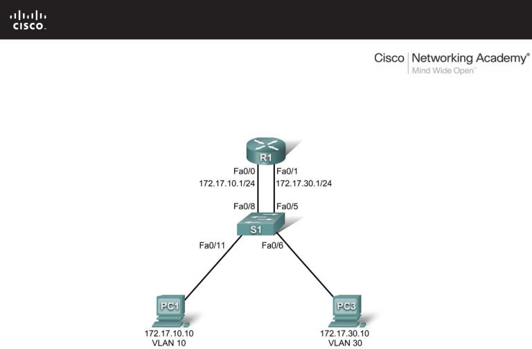
Topology Diagram
Addressing Table
|
Device |
|
Interface |
IP Address |
|
Subnet Mask |
|
|
Default Gateway |
|
|
|
|
|
|
|
|
|
|
|
R1 |
|
Fa0/0 |
172.17.10.1 |
|
255.255.255.0 |
|
|
N/A |
|
|
|
|
|
|
|
|
|
|
|
|
Fa0/1 |
172.17.30.1 |
|
255.255.255.0 |
|
|
N/A |
|
|
|
|
|
|
|
||||
|
|
|
|
|
|
|
|
|
|
|
PC1 |
|
NIC |
172.17.10.10 |
|
255.255.255.0 |
|
172.17.10.1 |
|
|
|
|
|
|
|
|
|
|
|
|
PC3 |
|
NIC |
172.17.30.10 |
|
255.255.255.0 |
|
172.17.30.1 |
|
|
|
|
|
|
|
|
|
|
|
Learning Objectives
•Test connectivity without inter-VLAN routing.
•Add VLANs to a switch.
•Configure IP addressing on a router.
•Test connectivity with inter-VLAN routing.
Introduction
In this activity, you will configure traditional inter-VLAN routing simply by configuring two Fast Ethernet interfaces on a router. R1 has two connections to S1—one for each of the two VLANs. S1 and R1 already have basic configurations. The user EXEC password is cisco, and the privileged EXEC password is class. You will complete the configuration by adding VLANs to S1 and assigning VLANs to the correct ports. Then you will configure R1 with IP addressing. In traditional inter-VLAN routing, there are no additional, VLAN-related configurations needed on R1.
All contents are Copyright © 1992–2007 Cisco Systems, Inc. All rights reserved. This document is Cisco Public Information. |
Page 1 of 3 |

CCNA Exploration |
|
LAN Switching and Wireless: Inter-VLAN Routing |
PT Activity 6.2.2.4: Configuring Traditional Inter-VLAN Routing |
Task 1: Test Connectivity without Inter-VLAN Routing
Step 1. Ping between PC1 and PC3.
Wait for switch convergence. The link lights on the switch connecting to PC1 and PC3 change from amber to green. When the link lights are green, ping between PC1 and PC3. Because the two PCs are on separate networks and the router is not configured, they cannot communicate with one another, so the ping fails.
Step 2. Switch to Simulation mode to monitor pings.
•Switch to Simulation mode by clicking the Simulation tab or pressing Shift+S
•Use the Add Simple PDU tool to ping between PC1 and PC3.
•Click Capture/Forward to see the steps the ping takes between PC1 and PC3.
•Notice how the ping cannot even cross the switch.
Your completion percentage should be 0%.
Task 2: Add VLANs
Step 1. Create VLANs on S1.
Return to Realtime mode. Create two VLANs on S1, one for PC1 and one for PC3. PC1 belongs to VLAN 10, and PC3 belongs to VLAN 30. To create the VLANs, issue the vlan 10 and vlan 30 commands in global configuration mode.
S1#configure terminal
S1(config)#vlan 10 S1(config-vlan)#vlan 30
To check whether the VLANs were created, issue the show vlan brief command from the privileged EXEC prompt.
S1#show vlan brief |
Status |
Ports |
|
VLAN Name |
|||
---- ------------------------------ |
--------- |
------------------------------- |
|
1 |
default |
active |
Fa0/1, Fa0/2, Fa0/3, Fa0/4 |
|
|
|
Fa0/5, Fa0/6, Fa0/7, Fa0/8 |
|
|
|
Fa0/9, Fa0/10, Fa0/11, Fa0/12 |
|
|
|
Fa0/13, Fa0/14, Fa0/15, Fa0/16 |
|
|
|
Fa0/17, Fa0/18, Fa0/19, Fa0/20 |
|
|
|
Fa0/21, Fa0/22, Fa0/23, Fa0/24 |
10 |
VLAN0010 |
active |
Gig1/1, Gig1/2 |
|
|||
30 |
VLAN0030 |
active |
|
1002 |
fddi-default |
active |
|
1003 |
token-ring-default |
active |
|
1004 |
fddinet-default |
active |
|
1005 |
trnet-default |
active |
|
Step 2. Assign the VLANs to ports.
Each port on the switch is assigned to a VLAN to allow for inter-VLAN communication. Assign the switch ports as follows:
• Assign the Fa0/5 and Fa0/6 interfaces to VLAN 30.
• Assign the Fa0/8 and Fa0/11 interfaces to VLAN 10.
All contents are Copyright © 1992–2007 Cisco Systems, Inc. All rights reserved. This document is Cisco Public Information. Page 2 of 3

CCNA Exploration |
|
LAN Switching and Wireless: Inter-VLAN Routing |
PT Activity 6.2.2.4: Configuring Traditional Inter-VLAN Routing |
To assign a VLAN to a port, enter the interface configuration. For Fa0/8, the command is interface fa0/8. The switchport access vlan 10 assigns VLAN 10 to that port. The switchport mode access command sets the port to access mode.
S1(config)#interface fa0/8 S1(config-if)#switchport mode access S1(config-if)#switchport access vlan 10
Repeat the above steps for Fa0/5, Fa0/6, and Fa0/11, assigning the correct VLANs to each interface.
Step 3. Test connectivity between PC1 and PC3.
Now issue a ping between PC1 and PC3. The ping should still fail.
Step 4. Check results.
Your completion percentage should be 45%. If not, click Check Results to see which required components are not yet completed.
Task 3: Configure IP Addressing
Step 1. Configure IP addressing on R1.
Configure the Fa0/0 interface of R1 with the IP address 172.17.10.1 and subnet mask 255.255.255.0. Configure the Fa0/1 interface with the IP address 172.17.30.1 and subnet mask 255.255.255.0. Issue the no shutdown command on both interfaces to bring them up.
R1(config)#interface fa0/0
R1(config-if)#ip address 172.17.10.1 255.255.255.0
R1(config-if)#no shutdown R1(config-if)#interface fa0/1
R1(config-if)#ip address 172.17.30.1 255.255.255.0
R1(config-if)#no shutdown
Step 2. Check results.
Your completion percentage should be 100%. If not, click Check Results to see which required components are not yet completed.
Task 4: Test Connectivity Again
Step 1. Ping between PC1 and PC3.
Wait for STP to converge. Then ping from PC1 to PC3. The ping should succeed.
Step 2. Switch to simulation mode to monitor pings.
•Switch to simulation mode by clicking the Simulation tab or pressing Shift+S.
•Click Capture/Forward to see the steps the ping takes between PC1 and PC3.
•Watch as the ping goes from PC1 through S1, then to R1, then back to S1, and finally to the PC3.
All contents are Copyright © 1992–2007 Cisco Systems, Inc. All rights reserved. This document is Cisco Public Information. |
Page 3 of 3 |
PT Activity 6.2.2.5: Configuring Router-on-a-Stick Inter-VLAN Routing
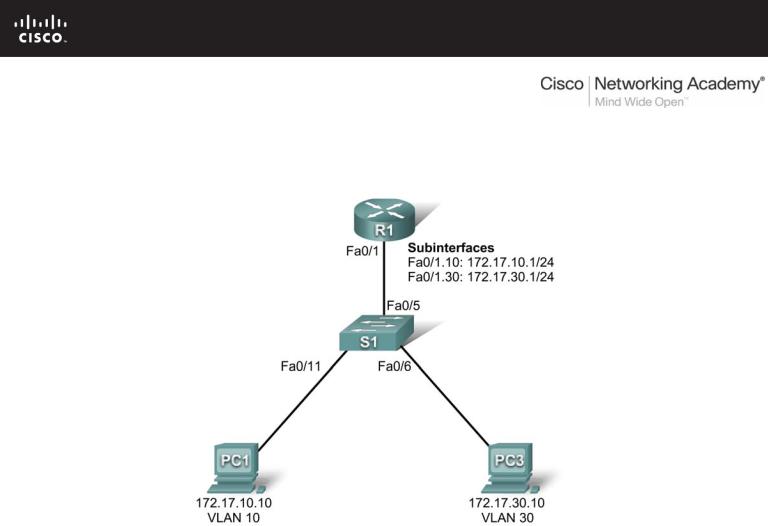
Topology Diagram
Addressing Table
|
Device |
|
Interface |
IP Address |
|
Subnet Mask |
|
|
Default Gateway |
|
|
|
|
|
|
|
|
|
|
|
R1 |
|
Fa0/1.10 |
172.17.10.1 |
|
255.255.255.0 |
|
|
N/A |
|
|
|
|
|
|
|
|
|
|
|
|
Fa0/1.30 |
172.17.30.1 |
|
255.255.255.0 |
|
|
N/A |
|
|
|
|
|
|
|
||||
|
|
|
|
|
|
|
|
|
|
|
PC1 |
|
NIC |
172.17.10.10 |
|
255.255.255.0 |
|
172.17.10.1 |
|
|
|
|
|
|
|
|
|
|
|
|
PC3 |
|
NIC |
172.17.30.10 |
|
255.255.255.0 |
|
172.17.30.1 |
|
|
|
|
|
|
|
|
|
|
|
Learning Objectives
•Test connectivity without inter-VLAN routing.
•Add VLANs to a switch.
•Configure IP addressing on a router.
•Test connectivity with inter-VLAN routing.
Introduction
In this activity, you will configure Router-on-a-Stick inter-VLAN routing. R1 has one connection to S1. S1 and R1 already have basic configurations. The user EXEC password is cisco, and the privileged EXEC password is class. You will complete the configuration by adding VLANs to S1 and assigning VLANs to the correct ports. Then you will configure R1 with subinterfaces, 802.1Q encapsulation, and IP addressing.
All contents are Copyright © 1992–2007 Cisco Systems, Inc. All rights reserved. This document is Cisco Public Information. |
Page 1 of 4 |

CCNA Exploration |
|
LAN Switching and Wireless: Inter-VLAN Routing |
PT Activity 6.2.2.5: Configuring Router-on-a-Stick Inter-VLAN Routing |
Task 1: Test Connectivity without Inter-VLAN Routing
Step 1. Ping between PC1 and PC3.
Wait for switch convergence. The link lights on the switch connecting to PC1 and PC3 change from amber to green. When the link lights are green, ping between PC1 and PC3. Because the two PCs are on separate networks and inter-VLAN routing is not configured, they cannot communicate with one another, so the ping fails.
Step 2. Switch to Simulation mode to monitor pings.
•Switch to Simulation mode by selecting the Simulation tab or pressing Shift+S.
•Click Capture/Forward to see the steps the ping takes between PC1 and PC3.
•Notice how the ping cannot even cross the switch.
Your completion percentage should be 0%.
Task 2: Add VLANs
Step 1. Create VLANs on S1.
Return to Realtime mode. Using cisco as the user EXEC password and class as the privileged EXEC password, create VLAN 10 and VLAN 30 on S1. PC1 belongs to VLAN 10, and PC2 belongs to VLAN 30. To create the VLANs, issue the vlan 10 and vlan 30 commands in global configuration mode.
S1#configure terminal
S1(config)#vlan 10 S1(config-vlan)#vlan 30
To check whether the VLANs were created, issue the show vlan brief command from the privileged EXEC prompt.
S1#show vlan brief
VLAN |
Name |
Status |
Ports |
---- |
------------------------------ |
--------- |
------------------------------- |
1 |
default |
active |
Fa0/1, Fa0/2, Fa0/3, Fa0/4 |
|
|
|
Fa0/5, Fa0/6, Fa0/7, Fa0/8 |
|
|
|
Fa0/9, Fa0/10, Fa0/11, Fa0/12 |
|
|
|
Fa0/13, Fa0/14, Fa0/15, Fa0/16 |
|
|
|
Fa0/17, Fa0/18, Fa0/19, Fa0/20 |
|
|
|
Fa0/21, Fa0/22, Fa0/23, Fa0/24 |
10 |
VLAN0010 |
active |
Gig1/1, Gig1/2 |
|
|||
30 |
VLAN0030 |
active |
|
1002 |
fddi-default |
active |
|
1003 |
token-ring-default |
active |
|
1004 |
fddinet-default |
active |
|
1005 |
trnet-default |
active |
|
Step 2. Assign the VLANs to ports.
Each port is assigned to a VLAN to allow for inter-VLAN communication. The Fa0/11 interface belongs to VLAN 10, and the Fa0/6 interface belongs to VLAN 30.
To assign a VLAN to a port, enter interface configuration mode. For Fa0/11, the command is interface fa0/11. Issue the switchport mode access command to set the port to access mode. The switchport access vlan 10 command assigns VLAN 10 to that port.
S1(config-if)#interface fa0/11
All contents are Copyright © 1992–2007 Cisco Systems, Inc. All rights reserved. This document is Cisco Public Information. Page 2 of 4
CCNA Exploration |
|
LAN Switching and Wireless: Inter-VLAN Routing |
PT Activity 6.2.2.5: Configuring Router-on-a-Stick Inter-VLAN Routing |
S1(config-if)#switchport mode access
S1(config-if)#switchport access vlan 10
Repeat the steps for the Fa0/6 interface for VLAN 30.
S1(config)#interface fa0/6
S1(config-if)#switchport mode access
S1(config-if)#switchport access vlan 30
The Fa0/5 port on S1 is set to trunk, which allows it to carry information from both VLAN 10 and VLAN 30. From the Fa0/5 interface, issue the switchport mode trunk command to set the port to trunk. Packet Tracer does not grade this command, but it is necessary in configuring inter-VLAN routing.
S1(config-if)#interface fa0/5
S1(config-if)#switchport mode trunk
Step 3. Test connectivity between PC1 and PC3.
Now issue a ping between PC1 and PC3. The ping should still fail.
Step 4. Check results.
Your completion percentage should be 27%. If not, click Check Results to see which required components are not yet completed.
Task 3: Configure IP addressing
Step 1. Configure subinterfaces with 802.1Q encapsulation.
Using cisco as the user EXEC password and class as the privileged EXEC password, create two subinterfaces on R1: Fa0/1.10 and Fa0/1.30. These subinterfaces are assigned to VLANs. To create the first subinterface, enter subinterface configuration mode for Fa0/1.10 by issuing the interface fa0/1.10 command. Notice that the router prompt changes.
While in subinterface configuration mode, issue the encapsulation dot1Q 10 command to set the encapsulation type to 802.1Q and assign VLAN 10 to the virtual interface.
Assign the correct IP address to the port. For Fa0/1.10, it is 172.17.10.1 with a subnet mask of 255.255.255.0.
Repeat these steps for the Fa0/1.30 interface using the correct IP address and VLAN ID.
R1(config)#interface fa0/1.10 R1(config-subif)#encapsulation dot1Q 10 R1(config-subif)#ip address 172.17.10.1 255.255.255.0
R1(config-subif)#interface fa0/1.30
R1(config-subif)#encapsulation dot1Q 30 R1(config-subif)#ip address 172.17.30.1 255.255.255.0
Step 2. Check results.
Your completion percentage should be 100%. If not, click Check Results to see which required components are not yet completed.
Task 4: Test Connectivity Again
Step 1. Ping between PC1 and PC3.
Ping from PC1 to PC3. The ping should succeed.
All contents are Copyright © 1992–2007 Cisco Systems, Inc. All rights reserved. This document is Cisco Public Information. |
Page 3 of 4 |

CCNA Exploration |
|
LAN Switching and Wireless: Inter-VLAN Routing |
PT Activity 6.2.2.5: Configuring Router-on-a-Stick Inter-VLAN Routing |
Step 2. Switch to Simulation mode to monitor pings.
•Switch to Simulation mode by selecting the Simulation tab or pressing Shift+S.
•Click Capture/Forward to see the steps the ping takes between PC1 and PC3.
•Watch how the ping travels from PC1 through S1 first, then to R1, then back to S1, and finally to the PC3.
All contents are Copyright © 1992–2007 Cisco Systems, Inc. All rights reserved. This document is Cisco Public Information. |
Page 4 of 4 |