

Chapter09
.pdfChapter 9, Problem 75.
Design a circuit that will transform a sinusoidal voltage input to a cosinusoidal voltage output.
Chapter 9, Solution 75.
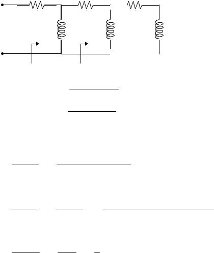
Since cos(ωt) = sin(ωt +90°) , we need a phase shift circuit that will cause the
output to lead the input by 90°. This is achieved by the RL circuit shown below, as explained in the previous problem.
|
10 Ω |
10 Ω |
+ |
|
+ |
Vi |
j10 Ω |
j10 Ω Vo |
− |
|
− |
This can also be obtained by an RC circuit.
Chapter 9, Problem 76.
For the following pairs of signals, determine if v1 leads or lags v 2 and by how much.
(a) v1 |
= 10 cos(5t - 20 o ), |
v 2 |
= 8 sin5t |
|
(b) v1 |
= 19 cos(2t - 90 o ), |
v 2 |
= 6 sin2t |
|
(c) v1 |
= - 4 cos10t , |
v 2 |
= 15 sin10t |
|
Chapter 9, Solution 76.
(a)v2 =8sin 5t =8cos(5t −90o ) v1 leads v2 by 70o.
(b)v2 = 6sin 2t = 6cos(2t −90o )
v1 leads v2 by 180o.
(c ) v1 = −4cos10t = 4cos(10t +180o ) v2 =15sin10t =15cos(10t −90o ) v1 leads v2 by 270o.
PROPRIETARY MATERIAL. © 2007 The McGraw-Hill Companies, Inc. All rights reserved. No part of this Manual may be displayed, reproduced or distributed in any form or by any means, without the prior written permission of the publisher, or used beyond the limited distribution to teachers and educators permitted by McGraw-Hill for their individual course preparation. If you are a student using this Manual, you are using it without permission.

Chapter 9, Problem 77.
Refer to the RC circuit in Fig. 9.81.
(a)Calculate the phase shift at 2 MHz.
(b)Find the frequency where the phase shift is 45 o .
Figure 9.81
For Prob. 9.77.
Chapter 9, Solution 77.
(a) |
V = |
- jXc |
|
V |
|
|
|
|
|
||
|
|
|
|
|
|
|
|||||
|
|
o |
|
|
|
i |
|
|
|
|
|
|
|
|
|
R − jXc |
|
|
|
|
|
||
|
where |
Xc = |
1 |
= |
1 |
|
= 3.979 |
||||
|
ωC |
|
(2π)(2 ×10⁶ )(20 ×10-9 ) |
||||||||
|
|
Vo |
= |
- j3.979 = |
3.979 |
(-90°+ tan-1 (3.979 5)) |
|||||
|
|
Vi |
|
5 - j3.979 |
|
52 +3.9792 |
|
|
|||
|
|
Vo |
= |
3.979 |
|
(-90°−38.51°) |
|
||||
|
|
Vi |
|
25 +15.83 |
|
|
|
|
|||
|
|
Vo |
= 0.6227 - 51.49° |
|
|
||||||
|
|
V |
|
|
|||||||
|
|
|
|
|
|
|
|
|
|
|
|
|
|
i |
|
|
|
|
|
|
|
|
|
Therefore, the phase shift is 51.49° lagging
(b)θ= -45°= -90°+ tan-1 (Xc  R)
R)
45°= tan-1 (X |
c |
R) |
→ R = X |
c |
= |
1 |
||||||
|
|
|
1 |
|
|
|
|
ωC |
||||
ω= 2πf = |
|
|
|
|
|
|
|
|
||||
RC |
|
|
|
|
|
|
||||||
1 |
|
|
|
|
|
|
1 |
= 1.5915 MHz |
||||
f = |
|
|
= |
|
||||||||
2πRC |
(2π)(5)(20 ×10-9 ) |
|||||||||||
PROPRIETARY MATERIAL. © 2007 The McGraw-Hill Companies, Inc. All rights reserved. No part of this Manual may be displayed, reproduced or distributed in any form or by any means, without the prior written permission of the publisher, or used beyond the limited distribution to teachers and educators permitted by McGraw-Hill for their individual course preparation. If you are a student using this Manual, you are using it without permission.

Chapter 9, Problem 78.
A coil with impedance 8 + j6 Ω is connected in series with a capacitive reactance X. The series combination is connected in parallel with a resistor R. Given that the equivalent
impedance of the resulting circuit is 5 0 o Ω find the value of R and X.
Chapter 9, Solution 78.
8+j6
R
Z
-jX
Z |
= R //[8 |
+ j(6 − X )]= |
R[8 + j(6 − X )] |
|
= 5 |
|
R +8 + j(6 − X ) |
|
|||||
|
|
|
|
|
||
i.e 8R + j6R – jXR = 5R + 40 + j30 –j5X |
|
|
||||
Equating real and imaginary parts: |
|
|
||||
|
|
8R = 5R + 40 which leads to |
R=13.333Ω |
|||
|
|
6R-XR =30-5X which leads to |
X= 6 Ω. |
|||
PROPRIETARY MATERIAL. © 2007 The McGraw-Hill Companies, Inc. All rights reserved. No part of this Manual may be displayed, reproduced or distributed in any form or by any means, without the prior written permission of the publisher, or used beyond the limited distribution to teachers and educators permitted by McGraw-Hill for their individual course preparation. If you are a student using this Manual, you are using it without permission.

Chapter 9, Problem 79.
(a)Calculate the phase shift of the circuit in Fig. 9.82.
(b)State whether the phase shift is leading or lagging (output with respect to input).
(c)Determine the magnitude of the output when the input is 120 V.
Figure 9.82
For Prob. 9.79.
PROPRIETARY MATERIAL. © 2007 The McGraw-Hill Companies, Inc. All rights reserved. No part of this Manual may be displayed, reproduced or distributed in any form or by any means, without the prior written permission of the publisher, or used beyond the limited distribution to teachers and educators permitted by McGraw-Hill for their individual course preparation. If you are a student using this Manual, you are using it without permission.
Chapter 9, Solution 79.
(a)Consider the circuit as shown.
|
|
20 Ω |
V2 |
|
40 Ω |
|
V1 |
30 Ω |
|
|
+ |
|
|
|
|
|
|
|
+ |
|
Vi |
j10 Ω |
|
|
j30 Ω |
j60 Ω Vo |
|||
|
− |
|
|
|
|
|
|
|
− |
|
|
Z2 |
|
|
|
Z1 |
|
|
|
Z1 |
= j30 || (30 + j60) = |
( j30)(30 + j60) |
= 3 + j21 |
||||||
|
|
|
|
|
|
30 + j90 |
|
||
Z2 |
= j10 || (40 + Z1 ) = |
( j10)(43 + j21) |
=1.535 + j8.896 = 9.028 80.21° |
||||||
|
|
|
|
|
|
43 + j31 |
|
||
Let Vi =1 0°. |
|
|
|
|
|
|
|||
|
|
Z2 |
|
(9.028 80.21°)(1 0°) |
|||||
V2 |
= |
Z2 + 20 Vi = |
|
21.535 + j8.896 |
|||||
V2 |
= 0.3875 57.77° |
|
|
|
|
|
|||
|
|
Z1 |
|
3 + j21 |
|
(21.213 81.87°)(0.3875 57.77°) |
|||
V1 |
= |
Z1 + 40 V2 = |
43 + j21 V2 |
= |
|
47.85 26.03° |
|||
V1 = 0.1718 113.61° |
|
|
|
|
|
||||
V = |
j60 |
V = |
j2 |
V = |
2 |
(2 + j)V |
|||
o |
|
30 + j60 |
1 |
1+ j2 |
1 |
5 |
|
1 |
|
Vo = (0.8944 26.56°)(0.1718 113.6°) |
|||||||||
Vo |
= 0.1536 140.2° |
|
|
|
|
|
|||
Therefore, the phase shift is 140.2°
(b)The phase shift is leading.
(c)If Vi =120 V , then
Vo = (120)(0.1536 140.2°) =18.43 140.2°V and the magnitude is 18.43 V.
PROPRIETARY MATERIAL. © 2007 The McGraw-Hill Companies, Inc. All rights reserved. No part of this Manual may be displayed, reproduced or distributed in any form or by any means, without the prior written permission of the publisher, or used beyond the limited distribution to teachers and educators permitted by McGraw-Hill for their individual course preparation. If you are a student using this Manual, you are using it without permission.

Chapter 9, Problem 80.
Consider the phase-shifting circuit in Fig. 9.83. Let V i = 120 V operating at 60 Hz. Find:
(a)V o when R is maximum
(b)V o when R is minimum
(c)the value of R that will produce a phase shift of 45 o
Figure 9.83
For Prob. 9.80.
Chapter 9, Solution 80.
|
200 mH → |
jωL = j(2π)(60)(200 ×10-3 ) = j75.4 Ω |
||
|
j75.4 |
j75.4 |
|
|
Vo = |
|
Vi = |
|
(120 0°) |
R +50 + j75.4 |
R +50 + j75.4 |
|||
(a)When R =100 Ω,
V = |
j75.4 |
(120 0°) = |
(75.4 90°)(120 0°) |
||
|
|
||||
o |
150 |
+ j75.4 |
|
167.88 26.69° |
|
|
|
||||
Vo = 53.89 63.31° V
(b)When R = 0 Ω,
V = |
|
j75.4 |
(120 0°) = |
(75.4 90°)(120 0°) |
|
|
|
|
|||
o |
|
50 |
+ j75.4 |
|
90.47 56.45° |
|
|
|
|||
Vo |
= |
100 33.55° V |
|||
(c)To produce a phase shift of 45°, the phase of Vo = 90° + 0° − α = 45°.
Hence, α = phase of (R + 50 + j75.4) = 45°.
For α to be 45°, |
R + 50 = 75.4 |
Therefore, |
R = 25.4 Ω |
PROPRIETARY MATERIAL. © 2007 The McGraw-Hill Companies, Inc. All rights reserved. No part of this Manual may be displayed, reproduced or distributed in any form or by any means, without the prior written permission of the publisher, or used beyond the limited distribution to teachers and educators permitted by McGraw-Hill for their individual course preparation. If you are a student using this Manual, you are using it without permission.
Chapter 9, Problem 81.
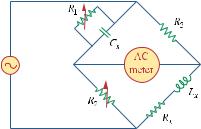
The ac bridge in Fig. 9.37 is balanced when R1 |
= 400 Ω, R 2 |
= 600 Ω, R 3 = 1.2k Ω, and |
|||||||||||||||||||||||||||||||||||
C 2 = 0.3 µF . Find R x |
and C x . Assume R 2 and C 2 |
are in series. |
|
|
|
|
|||||||||||||||||||||||||||||||
Chapter 9, Solution 81. |
|
|
|
|
|
|
|
|
|
1 |
|
|
|
|
|
|
|
1 |
|
||||||||||||||||||
|
|
|
|
|
|
|
|
|
|
|
|
|
|
|
|
|
|
|
|
|
|
|
|
|
|
|
|
|
|
|
|
|
|
||||
Let |
|
|
|
Z1 = R1 , |
|
|
|
Z2 |
= R 2 + |
|
|
, |
|
Z3 = R 3 , and |
Zx = R x + |
|
. |
||||||||||||||||||||
|
|
|
|
|
jωC2 |
|
jωCx |
||||||||||||||||||||||||||||||
Zx |
= |
|
Z3 |
|
Z2 |
|
|
|
|
|
|
|
|
|
|
|
|
|
|
|
|
|
|
|
|
|
|
|
|
|
|
|
|||||
|
|
|
|
|
|
|
|
|
|
|
|
|
|
|
|
|
|
|
|
|
|
|
|
|
|
|
|
|
|||||||||
|
|
|
|
|
Z1 |
|
|
|
|
|
|
|
|
|
|
|
|
|
|
|
|
|
|
|
|
|
|
|
|
|
|
|
|
|
|
||
|
|
|
|
|
1 |
|
|
|
|
|
R |
3 |
|
|
|
|
1 |
|
|
|
|
|
|
|
|
|
|
|
|
||||||||
R |
x |
+ |
|
|
|
|
|
|
= |
|
|
|
|
R |
2 |
+ |
|
|
|
|
|
|
|
|
|
|
|
|
|
|
|
||||||
|
|
|
|
|
|
|
|
|
|
|
|
|
|
|
|
|
|
|
|
|
|
|
|
|
|||||||||||||
|
|
|
|
jωCx |
|
|
R1 |
|
jωC2 |
|
|
|
|
|
|
|
|
|
|
|
|
||||||||||||||||
R x |
= |
|
R 3 |
R 2 |
= |
1200 |
|
(600) = 1.8 kΩ |
|
|
|
|
|
|
|
|
|
|
|
||||||||||||||||||
|
R1 |
|
400 |
|
|
|
|
|
|
|
|
|
|
|
|
||||||||||||||||||||||
|
|
|
|
|
|
|
|
|
|
|
|
|
|
|
|
|
|
|
|
|
|
|
|
|
|
|
|
|
|
|
|||||||
1 |
|
|
R |
3 |
|
|
1 |
|
|
|
|
|
|
|
|
|
|
R |
1 |
|
|
|
400 |
|
|
|
|
|
|||||||||
|
|
|
|
|
|
|
|
|
|
|
|
|
|
|
|
|
|
|
|
|
|
|
|
|
|
|
|
|
|
-6 |
) = 0.1 µF |
||||||
|
|
|
|
|
|
|
|
|
|
|
|
|
|
|
|
|
|
|
|
|
|
|
|
|
|
|
|||||||||||
|
Cx |
= R1 C2 |
→ |
Cx = R 3 |
C2 |
= |
|
×10 |
|
||||||||||||||||||||||||||||
|
1200 (0.3 |
|
|||||||||||||||||||||||||||||||||||
Chapter 9, Problem 82.
A capacitance bridge balances when R1 = 100 Ω, and R 2 = 2k Ω and C s = 40 µF . What is C x the capacitance of the capacitor under test?
Chapter 9, Solution 82.
|
R |
1 |
|
100 |
|
|
|
|
|
|
|
|
|
|
|
|
|
-6 |
) = 2 |
µF |
|
Cx = R 2 Cs = |
|
|
||||||||
2000 |
(40 ×10 |
|
||||||||
Chapter 9, Problem 83. |
|
|
|
|
|
|
|
|||
An inductive bridge balances when R1 |
= 1.2k Ω, R 2 |
= 500 Ω, and L s = 250 mH. What |
||||||||
is the value of L x , the inductance of the inductor under test?
Chapter 9, Solution 83.
|
R |
2 |
|
|
500 |
|
|
|
|
Lx = |
|
Ls = |
|
|
|
×10 |
-3 |
) = 104.17 mH |
|
R1 |
|
||||||||
1200 |
(250 |
|
|||||||
PROPRIETARY MATERIAL. © 2007 The McGraw-Hill Companies, Inc. All rights reserved. No part of this Manual may be displayed, reproduced or distributed in any form or by any means, without the prior written permission of the publisher, or used beyond the limited distribution to teachers and educators permitted by McGraw-Hill for their individual course preparation. If you are a student using this Manual, you are using it without permission.
Chapter 9, Problem 84.
The ac bridge shown in Fig. 9.84 is known as a Maxwell bridge and is used for accurate measurement of inductance and resistance of a coil in terms of a standard capacitance C s Show that when the bridge is balanced,
L x = R 2 R 3 C s |
and |
R x = |
R2 |
R 3 |
|
R1 |
|||||
|
|
|
|
||
Find L x and R x |
for R1 = 40k |
Ω, R 2 = 1.6k Ω, R 3 = 4k Ω, and C s = 0.45 µ F. |
|||
Figure 9.84
Maxwell bridge; For Prob. 9.84.
PROPRIETARY MATERIAL. © 2007 The McGraw-Hill Companies, Inc. All rights reserved. No part of this Manual may be displayed, reproduced or distributed in any form or by any means, without the prior written permission of the publisher, or used beyond the limited distribution to teachers and educators permitted by McGraw-Hill for their individual course preparation. If you are a student using this Manual, you are using it without permission.

Chapter 9, Solution 84.
Let Z1 |
= R |
1 |
|
|
|
|
|
|
Z2 = R 2 , |
Z3 = R 3 , and Zx = R x + jωLx . |
|||||||||
1 || |
|
|
|
|
, |
|
|||||||||||||
jωCs |
|||||||||||||||||||
|
|
|
|
|
|
R1 |
|
|
|
|
|
|
|
|
|
|
|||
Z1 |
= |
|
|
|
jωCs |
|
= |
|
R1 |
|
|
|
|
||||||
|
1 |
|
|
jωR1Cs +1 |
|
|
|||||||||||||
|
|
|
R1 + |
jωCs |
|
|
|
|
|
|
|
|
|
||||||
Since Zx = |
Z3 |
|
Z2 , |
|
|
|
|
|
|
|
|
|
|||||||
Z1 |
|
|
|
|
|
|
|
|
|
|
|||||||||
|
|
|
|
|
|
|
|
|
|
|
|
|
|
|
|
|
|
||
R x + jωLx = R 2 R 3 |
|
jωR1Cs +1 |
= |
R 2 R 3 |
(1+ jωR1Cs ) |
||||||||||||||
|
|
|
|||||||||||||||||
|
|
|
|
|
|
|
|
|
|
|
|
|
|
|
R1 |
R1 |
|||
Equating the real and imaginary components,
Rx = R2 R3
R1
ωLx = R 2 R 3 (ωR1Cs ) implies that R1
Lx = R 2 R3Cs
Given that R1 = 40 kΩ, R 2 =1.6 kΩ, R 3 = 4 kΩ, and Cs = 0.45 µF
R x = |
R 2 R 3 |
= |
(1.6)(4) |
kΩ= 0.16 kΩ= 160 Ω |
|
R1 |
40 |
||||
|
|
|
Lx = R 2 R 3Cs = (1.6)(4)(0.45) = 2.88 H
PROPRIETARY MATERIAL. © 2007 The McGraw-Hill Companies, Inc. All rights reserved. No part of this Manual may be displayed, reproduced or distributed in any form or by any means, without the prior written permission of the publisher, or used beyond the limited distribution to teachers and educators permitted by McGraw-Hill for their individual course preparation. If you are a student using this Manual, you are using it without permission.

Chapter 9, Problem 85.
The ac bridge circuit of Fig. 9.85 is called a Wien bridge. It is used for measuring the frequency of a source. Show that when the bridge is balanced,
f = |
1 |
|
|
|
|
2π R R C |
C |
4 |
|||
|
2 |
4 |
2 |
|
|
Figure 9.85
Wein bridge; For Prob. 9.85.
PROPRIETARY MATERIAL. © 2007 The McGraw-Hill Companies, Inc. All rights reserved. No part of this Manual may be displayed, reproduced or distributed in any form or by any means, without the prior written permission of the publisher, or used beyond the limited distribution to teachers and educators permitted by McGraw-Hill for their individual course preparation. If you are a student using this Manual, you are using it without permission.