

Task of the Work
To become familiar with mode of operation of frequency multiplier in transistor circuit; study methods of determination cut angle of signal by mean of research of oscillograms and determination the transfer coefficient of frequency multiplier.
Brief Theoretical Information
In electronics, a frequency multiplier is an electronic circuit that generates an output signal whose output frequency is a harmonic (multiple) of its input frequency. Frequency multipliers consist of a nonlinear circuit that distorts the input signal and consequently generates harmonics of the input signal. A subsequent bandpass filter selects the desired harmonic frequency and removes the unwanted fundamental and other harmonics from the output. Frequency multipliers are often used in frequency synthesizers and communications circuits. It can be more economical to develop a lower frequency signal with lower power and less expensive devices, and then use a frequency multiplier chain to generate an output frequency in the microwave or millimeter wave range. Some modulation schemes, such as frequency modulation, survive the nonlinear distortion without ill effect (but schemes such as amplitude modulation do not). Frequency multiplication is also used in nonlinear optics. The nonlinear distortion in crystals can be used to generate harmonics of laser light.
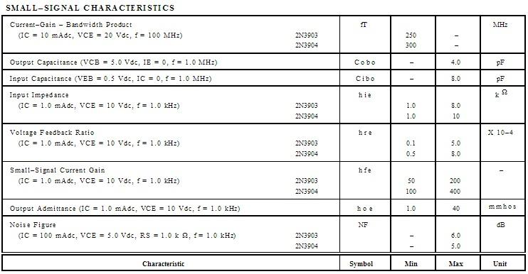
Parameters of transistor 2N3904 are represented in the Table 1.
Table 1.
Work Procedure
-
Principle circuit is represented on a fig. 1.
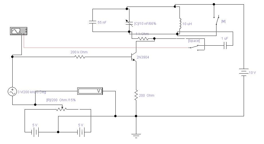
Fig. 1, Principle circuit of freguency multiplier.
Input signal is amplified by amplifier (in our case 2N3904) with common emitter, output signal is apllying to the input of oscillator. Oscillator are designed with possibility of change friquency of oscillations, oscillator tunes in resonance with some harmonic and such a way amplify it amplitude. As we know harmonics are multiple in whole number times corresponding to main frequency. So, we obtain allocation of multiple frequency, another words frequency multiplication.
-
Results of measurings and calculations, oscillograms of output voltages for different order of harmщnics.
|
|
Umax |
Umout |
K=Umout/Umax |
Θ(calc.) |
Θ(meas.) |
fin. |
|
k=1 |
3 |
7.1 |
1.68 |
120 deg. |
104 deg. |
200kHz |
|
k=2 |
3 |
2.35 |
0.56 |
60 deg. |
63 deg. |
100kHz |
|
k=3 |
3 |
2.14 |
0.51 |
40 deg. |
45.8 deg. |
66kHz |
|
k=4 |
3 |
1.25 V |
0.3 |
30 deg. |
45 deg. |
50kHz |


-
Graphs of certain number of harmonics are represented below:
-
k=1 ;
-
k=2;
-
k=3;
-
k=4;
a)
1-st harmonic, input signal 200kHz.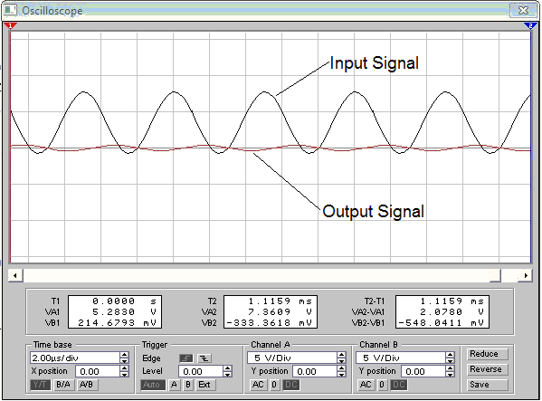
b)
2-nd harmonic, input signal 100kHz.
c)
3-rd harmonic, input signal 66kHz.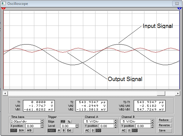
d)
4-th harmonic, input signal 50kHz.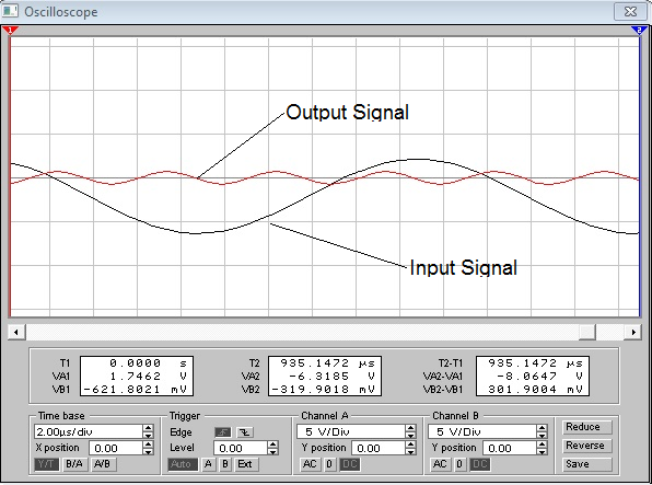
Conclusion. During this laboratory work I’ve learned how to determine cutoff angle and transfer coefficient of frequency multiplier, studied that with increasing the order of harmonic the frequency of harmonic becomes bigger in multiple number corresponds to input frequency. Frequency allocation is done by setting the oscillator in resonance with frequency of 1-st, 2-nd and other harmonics.