

Work Procedure
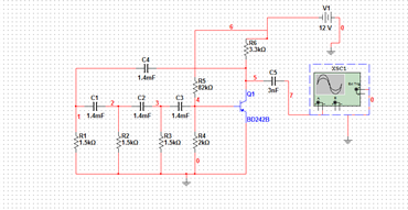
1. Calculate capacitance.
С=0,065/(R*F)=1,4 µF
2. Determine feedback coefficient.
β=Ufb/Uout=0,17
3. Determine gain coefficient.
Кu=6600mV\200mV=33mV
Кu*β=5.61>1 (умова автоколивань виконується)
So, on the base of this circuit we can construct RC - generator.
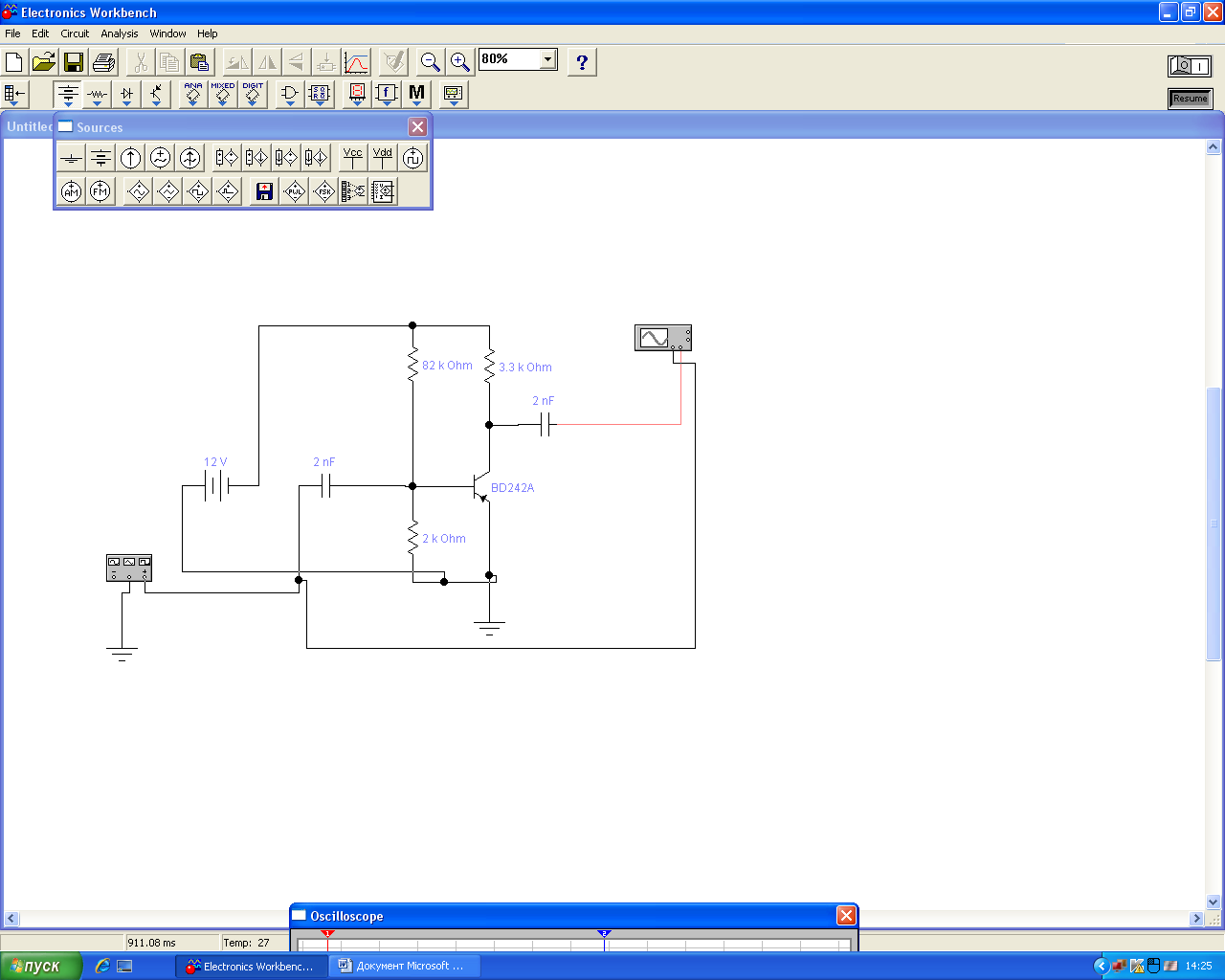
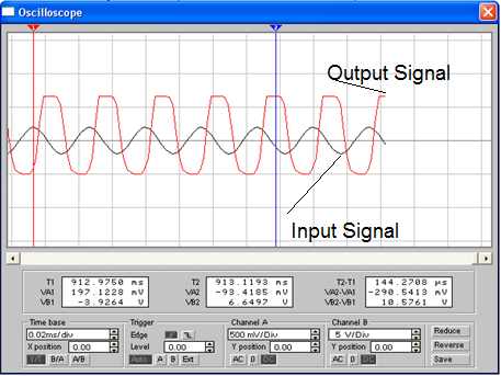
At the output we obtain signal

4. Determine the period.
Т=30 µS
f= 33 kHz
Conclusion. For the appearance of self - oscillation requires a positive feedback, with product feedback factor for the gain must be greater than one.
Task of the Work
To be familiar with a principle of operation of RC – generator.
Brief Theoretical Information
Linear electronic
oscillator circuits,
which generate a sinusoidal output
signal, are composed of an amplifier and
a frequency selective
element, a filter.
An oscillator circuit which uses an RC
network, a combination of resistors and capacitors,
for its frequency selective part is called an RC
oscillator.
Two
configurations are common. One is called a Wien
bridge oscillator. In this circuit, two RC circuits are used, one
with the RC components in series and one with the RC components in
parallel. The Wien Bridge is often used in audio signal
generators because it can be easily tuned using a
two-section variable
capacitor or a two section variable potentiometer (which is
more easily obtained than a variable capacitor suitable for
generation at low frequencies). The archetypical HP 200
audio oscillator is a Wien Bridge oscillator.
The
second common design is called a "Twin-T" oscillator as it
uses two "T" RC circuits operated in parallel. One circuit
is an R-C-R "T" which acts as a low-pass
filter. The second circuit is a C-R-C "T" which
operates as a high-pass
filter. Together, these circuits form a bridge which is tuned at
the desired frequency of oscillation. The signal in the C-R-C branch
of the Twin-T filter is advanced, in the R-C-R - delayed, so they may
cancel one another for frequency ![]() if
if ![]() ;
if it is connected as a negative feedback to an amplifier, and x>2,
the amplifier becomes an oscillator.
;
if it is connected as a negative feedback to an amplifier, and x>2,
the amplifier becomes an oscillator.
Another common design is the phase-shift oscillator.
If they are to produce an undistorted sine wave, RC oscillators usually require some form of amplitude control. Many common designs simply use an incandescent lamp or a thermistor in the feedback circuit. These oscillators take advantage of the fact that the resistance of the tungsten filament of the lamp increases in proportion to its temperature, a thermistor works in a similar fashion. Operated well below the point at which the filament actually illuminates, increased amplitude of the feedback signal causes increased current flow in the filament thereby increasing the resistance of the filament. The increased resistance of the filament reduces the feedback signal, limiting the oscillator's signal to the linear range. (That is, clipping is prevented.) The HP 200 oscillator introduced this technique.
More-sophisticated oscillators measure the output level and use this as feedback to control the gain of the voltage-controlled amplifier within the oscillator. If the amplitude detector has a flat frequency response, then this negative feedback of the amplitude measurement will ensure that the oscillator has a constant output amplitude no matter what frequency it is set to generate.