

Cell Biology Protocols
.pdfand 30–500 nM for the clathrin. It is often useful to try several concentrations, to account for differences in protein activity.
7.Incubate 60 min at room temperature.
8.Prepare uranyl acetate stain. Lay a fresh piece of Parafilm on the bench, and place two 30 µl drops side by side on the Parafilm for each grid which will be stained. Lay out a piece of Whatman filter paper to blot buffer and stain from grids. Lay out a second piece of filter paper on which to set grids to air-dry.
9.Gently inject approximately 30 µl of buffer into the side injection port; this will raise the grid up above the surface of the Teflon block. Immediately grab the grid with forceps and lift it vertically off of the droplet.
10.Blot the grid briefly by touching it to the filter paper, then touch it to the first stain droplet and blot immediately. Touch the grid to the second stain droplet, leave for 30 s, and blot briefly.
This leaves a film of stain on the surface of the grid in which the protein is embedded. If the grids will be platinum shadowed, hold the grid to the filter paper for several seconds to ensure that the entire grid surface dries. Lay the grid on another piece of filter paper to dry.
11. For negative stain |
EM, grids can |
be examined in the |
EM immediately |
(see Figure 6.19). They are also stable for several weeks, at least, at room temperature.
12.If platinum shadowing is required, set up the vacuum evaporator with a 2 cm long piece of platinum wire coiled tightly round a piece of 1 mm thick tungsten wire. Place the grids to be shadowed on a rotary platform at an
PROTOCOL 6.25 |
291 |
angle of 10◦ to the line between the platform centre and the platinum coil. Create a vacuum in the evaporator. With a shield between the grids and the wire, turn on the current to the tungsten wire. When the platinum wire melts, remove the shield and the platinum will evaporate onto the grids. For rotary platinum shadowing, start rotation of the platform immediately before removing the shield. For single angle shadowing, the platform can remain stationary during the evaporation; 1–2 min of evaporation is usually sufficient, but trials may need to be done to account for differences in evaporators.
Notes
This procedure will take approximately 3 h. All reagents should be of the highest purity available, and buffers should be filtered before use.
1 Clathrin should be dialysed into HKM buffer and centrifuged for 20 min at 100 000gmax (e.g. 45 000 rpm in a Beckman TLA100 rotor) immediately prior to use to remove aggregates.
2 Lipid stocks were stored at −80 ◦C.
3 The addition of polyacrylic acid helps to prevent the stain from precipitating and forming uranyl acetate crystals.
4 It is important to ensure that the surface of the droplet is either flat or slightly concave. Overfilling the Teflon wells leads to a convex droplet surface, upon which the monolayer does not form properly. Also, filling the wells with too little volume (less than 35 µl, or depending on the geometry of the block) can lead to an uneven surface near the side injection port.
292 IN VITRO TECHNIQUES
5 Trace lipid contamination (e.g. PtdIns (4,5)P2) on the Teflon block can result in misleading negative controls. The Teflon block should be rinsed with hot water, then ethanol, and finally, soaked overnight in a mixture of chloroform/methanol to remove any protein or lipid residue. Hamilton syringes are also susceptible to trace lipid contamination.
References
1.Chiu, W., Avila-Sakar, A. J. and Schmid, M. F. (1997) Electron crystallography of macromolecular periodic arrays on phospholipid monolayers. Adv. Biophys., 34, 161–172.
2.Levy, D., Mosser, G., Lambert, O., Moeck, G. S., Bald, D. and Rigaud, J. L. (1999) Two-
dimensional crystallization on lipid layer: a successful approach for membrane proteins. J. Struct. Biol., 127(1), Aug, 44–52.
3. Ford, M. G., Mills, I. G., |
Peter, B. J., |
Val- |
lis, Y., Praefcke, G. J., |
Evans, P. R. |
and |
McMahon, H. T. (2002) Curvature of clathrincoated pits driven by epsin. Nature 419(6905), 361–366.
4.Ford, M. G., Pearse, B. M., Higgins, M. K., Vallis, Y., Owen, D. J., Gibson, A., Hopkins, C. R., Evans, P. R. and McMahon, H. T.
(2001) Simultaneous binding of PtdIns(4,5)P2 and clathrin by AP180 in the nucleation of clathrin lattices on membranes. Science, 291(5506), 1051–1055.

PROTOCOL 6.26
Golgi membrane tubule formation
William J. Brown, K. Chambers and A. Doody
Introduction
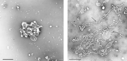
Membrane tubules emanate from a variety of organelles including the Golgi complex, endosomes and lysosomes [1]. These tubules are generally 60–80 nm in diameter, can extend for many microns in length, and are believed to play a role in various intracellular membrane trafficking pathways. Although recent studies strongly suggest a role for a cytoplasmic Ca2+-independent phospholipase A2 enzyme in initiating the formation of Golgi and endosome tubules [2, 3], the exact molecular mechanisms of tubule formation have not been elucidated. Progress in this area has been advanced by the development of an in vitro reconstitution system that was used to demonstrate that tubulation of Golgi membranes was absolutely dependent on cytosolic protein [4, 5]. This assay system should allow for the further characterization and identification of cytosolic factors that are required for tubules to form. This system should also provide a means to identify molecular differences between the tubules and the main body of the organelles from which they grow (see Figure 6.20).
Reagents
Carbonand formvar-coated electron microscope grids (300 mesh copper)
Extract of bovine brain cytosol (BBC) and isolated rat liver Golgi complexes,
prepared as described [3]. 1 (See also
Protocol 4.23)
2% w/v Phosphotungstic acid (PTA), pH
7.4 (stored at 4 ◦C)
Stock solutions: 10 mM Hepes, pH 7.4 (stored at −20 ◦C), 10 mM ATP (stored at −20 ◦C), 100 mM MgCl2 (stored at −20 ◦C), 25 mM Tris containing 50 mM KCl (pH 7.4)
Equipment
Eppendorf 500 µl microfuge tubes, or similar
Self-closing, fine-tipped forceps
Transmission electron microscope Water bath (37 ◦C)
Procedure
1.Thaw out all solutions and reagents and put on ice. Do not thaw out by running under hot water.
2.Pick up formvar/carbon-coated grids with the self-closing forceps. Hold the grids on the very edge. Be sure the grids look uniformly coated. Use a piece of white paper as a background.
3.Place the forceps on the white paper with coated grid side up. Use a box, e.g. the top of a pipette tip box, to cover the ends of the forceps to keep the grids from accumulating dust.
4.Place 500 µl microfuge tubes in an appropriate holder.
294 IN VITRO TECHNIQUES
(a) |
(b) |
Figure 6.20 (a) shows an example of a negatively stained Golgi stack that was incubated with BSA as a negative control. These control Golgi stacks generally appear somewhat round, with a few vesicles and possibly some short tubules. (b) shows a negatively stained Golgi stack that was incubated with BBC to induce tubule formation. Under these conditions, numerous tubules, 60–80 nm in diameter and ranging up to several microns in length, can be seen (arrows). Scale bars = 1 µm
5.Prepare Mg-ATP solution in the proportions below and put on ice. You will need 1 µl/reaction.
80 µl Tris/KCl stock buffer
10 µl ATP
10 µl MgCl2
6.Prepare the tubulation buffer containing BBC. You will need 20 µl/reaction (sample). When using BBC as a positive control, its final concentration
following dilution at this step should be 3 mg/ml. For negative controls, we use bovine serum albumin (BSA) at an equivalent concentration. For solutions with a high protein con-
centration (e.g. BBC, which is often prepared and stored at 20 mg/ml), use the following proportions: 85 µl 1 Tris/KCl, 1 µl Mg-ATP, 1 µl Hepes buffer, 13 µl BBC.
7.Add 20 µl of Golgi suspension to each microfuge tube.
8.Add 20 µl of tubulation buffer/BBC solution to the Golgi tubes. Add the tubulation buffer/BBC solution very
carefully to the Golgi suspension in three aliquots over 15 s. Gently mix.
9.Place tubes in 37 ◦C water bath and incubate for up to 30 min.
10.Take 10 µl of a sample and puddle
onto the grid that is being held by a forceps. Cover with the box top. Let the suspension sit on the grid for 15 min at room temperature.
11.Carefully add 10 µl of 2% PTA to the grid three times over 5 s. Do not let the puddle spill over the edges of the grid.
12.Blot off fluid from the edge of the grid with a moist kimwipe.
13.Add 10 µl of PTA to the grid and blot off fluid as in step 12. Repeat once more.
14.Let grids dry and then store until EM observation.
Notes
Preparation of BBC (or cytosolic preparations from other tissues/cells) will take 2 days. Preparation of rat liver Golgi complexes will take 1 day. The tubulation assay will take approximately 2 h.
1 Cytosolic extracts from other tissues can also be used. These reagents generally give the best results if freshly prepared, but they can be stored for several weeks at −80 ◦C and still give good results. However, they degrade with time, so use them as soon as possible.
References
1.Brown, W. J., Chambers, K. and Doody, A. (2003) Phospholipase A2 (PLA2) enzymes in
Protocol 6.26 |
295 |
membrane trafficking:mediators of membrane shape and function. Traffic, 4, 214–221.
2.De Figueiredo, P., Drecktrah, D., Katzenellenbogen, J. A., Strang, M. and Brown, W. J. (1998) Proc. Nat. Acad. Sci. USA, 95, 8642–8647.
3.De Figueiredo, P., Doody, A., Polizotto, R. S., Drecktrah, D., Wood, S., Banta, M., Strang, M. and Brown, W. J. (2001) J. Biol. Chem., 276, 47 361–47 370.
4.Banta, M., Polizotto, R. S., Wood, S. A., de Figueiredo, P. and Brown, W. J. (1995) Biochemistry, 34, 13 359–13 366.
5.Polizotto, R. S., de Figueiredo, P. and Brown, W. J. (1999) J. Cell Biochem., 74, 670–683.

PROTOCOL 6.27
Tight junction assembly
C. Yan Cheng and Dolores D. Mruk
Introduction
When mammalian epithelial cells, such as Sertoli cells, keratinocytes and MDCK cells (Madin Darby canine kidney cells), are cultured in vitro on a suitable substratum (e.g., Matrigel for Sertoli cells) in chemically defined medium (e.g., F12/ DMEM, Ham’s F12 Nutrient Mixture/ Dulbecco’s Modified Eagle’s medium for Sertoli cells) in either culture dishes or bicameral units, they assemble tight junctions (TJs) within days (for reviews, see refs 1–3). As such, this represents a useful in vitro system to investigate the biology and regulation of TJ dynamics (for reviews, see refs 3 and 4). There are several techniques available in the literature to monitor the assembly of epithelial cell TJs quantitatively or semi-quantitatively, which include restricted diffusion of [3H]- inulin, [125I]-BSA or FITC-dextran across the cell epithelium and maintenance of non-equilibrium of the fluid level between the apical and basal compartments of the bicameral unit [5, 6] (see Figure 6.21). While these techniques are helpful to monitor TJ assembly, they are either tedious, require the use of radioactive isotopes, or expensive equipment (such as a cytofluorometer to quantify FITC). We present herein the use of a Millicell Electrical Resistance System (ERS) (Millipore Corp.) to quantify the transepithelial electrical resistance (TER) across the cell
epithelium. This equipment is not expensive to purchase, the maintenance cost is also minimal (except for the electrodes which need periodic replacement), and yet an investigator can quantitatively assess the assembly, maintenance and/or regulation of TJs with precision and reproducibility. This technique has been tested vigorously against the other currently available methodologies [5–8], and it was shown to be the best technique to quantify TJ assembly in vitro.
Reagents and cell cultures
All reagents and enzymes used should be standard laboratory reagents prepared with Milli-Q quality water (such as PureLab PLUS from USFilter). Primary cultures of Sertoli cells are obtained from 20-day-old rat testes using procedures as
earlier |
described [5, 6, 9] and cultured on |
||
Matrigel-coated (Matrigel : F12/DMEM, |
|||
1 : 7) |
bicameral |
units |
(Millicell-HA |
0.45 µm-pore size |
culture |
plate insert |
|
composed of mixed esters of cellulose with 12 mm diameter; cat. no. PIHA 012 50, Millipore, Bedford, MA). Each treatment group should have at least triplicate culture inserts. Matrigel-coated bicam-
eral |
units should be |
prepared 24 h |
prior |
||
to cell plating |
and |
stored |
in a |
35 ◦C |
|
CO2 |
incubator |
(95% |
air/5% |
CO2, |
v/v) |
as described to allow the Matrigel to completely dry, which is essential to
Protocol 6.27 |
297 |
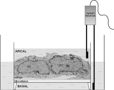
Figure 6.21 This is an electron micrograph that shows two Sertoli cells of an epithelium cultured on a Matrigel-coated bicameral unit (nitrocellulose based) on day 4. Ag/AgCl electrodes (one placed into the apical and the other into the basal compartment of the bicameral unit) are used to quantify the electrical resistance (in ohms) when an electrical current, 20 mA, is sent across the cell epithelium. Also note the non-equilibrium of the level of F12/DMEM between the two compartments when TJs are formed between cells. SC, Sertoli cell nucleus. This figure is adapted from Lee and Cheng [10] and used with permission from the publisher.
obtain TER readings with minimal intraexperimental variations. Care should also be taken to avoid trapping air bubbles in the Matrigel [6].
Equipment
Ag/AgCl electrodes (cat. no. MERS STX 01, Millipore) – electrodes need to be replaced after 12 months of routine use when visible loss of Ag/AgCl is detected. The electrodes are EVON chopstick electrodes. Each leaflet has an outer and inner electrode; the outer electrode is a small silver pad for passing current through the nitrocellulose membrane of the bicameral unit, whereas the inner electrode is a small Ag/AgCl voltage sensor
CO2 humidified incubator at 35 ◦C
Millipore Millicell ERS system (cat. no. MERS 000 01)
Centrifuge set at room temperature
Shaking water bath with variable temperature control
Standard laboratory microscope and transmission electron microscope (TEM)
Procedure for TER measurement
1.Sertoli cells isolated from seminiferous tubules immediately after their isolation
are plated immediately on Matrigelcoated bicameral units at 0.75–1 × 10⁶ cells/cm2 and designated time 0. Each culture insert is placed in a well of a 24-well dish with triplicate inserts for the control and each treatment group. Great care should be taken to avoid trapping air bubbles between Sertoli cells and the nitrocellulose membrane, which have a tendency to form on
298 IN VITRO TECHNIQUES
|
|
60 |
|
) |
50 |
electricalTransepithelial |
2 |
|
(TER,ohmresistance×cm |
40 |
|
|
|
|
|
|
30 |
|
|
20 |
|
|
10 |
|
|
0 |
Sertoli cells at 1.2 × 10⁶ cells/cm2
Sertoli cells at 5 × 10⁴ cells/cm2
1 |
1.5 |
2 |
3 |
3.5 |
4 |
5 |
6 |
7 |
Time of Sertoli cell culture (days)
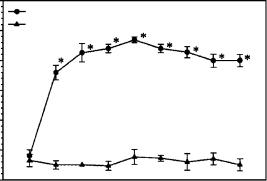
Figure 6.22 The assembly of the Sertoli cell TJ-permeability barrier in vitro as monitored by TER measurement across the Sertoli cell epithelium. In brief, Sertoli cells were cultured on Matrigel-coated bicameral units at either 1.2 × 10⁶ or 5 × 10⁴ cells/cm2. The TJ-barrier formed between Sertoli cells when they were cultured at 1.2 × 10⁶ cells/cm2 as manifested by a steady rise in the resistance across the cell epithelium, yet it failed to form at the lower cell density due to the lack of cell proximity. This figure is adopted from Mruk et al. [6] and used with permission from the publisher. *, p < 0.01 when compared to its corresponding control.
the periphery of the bicameral unit. Also, it is important that cells are uniformly plated to avoid uneven clustering of cells across the epithelium. Cells should not be disturbed thereafter for at least 2–4 h. The same volume of F12/DMEM ( 500 µl) should be used for the apical and basal compartments of the bicameral unit. The daily replacement of media should be of the same volume. By 4–5 h after plating, the first TER reading should be recorded and daily thereafter as follows:
•To test the instrument, switch the mode to RESISTANCE and turn the power ON. Press the TEST R button. With the RANGE SWITCH in the 2000 V position, the meter will read approximately 1000, whereas in the 20 k range, the meter will read 1.00. It is now ready for use.
•To test the electrodes, insert the end-plug at the end of the electrode cable into the front panel of the EVOM. Place the electrodes
into F12/DMEM. Turn the mode to VOLTS. Press the power switch ON. The reading will be 1–2 mV. After 15 min, adjust this voltage to 0 mV at the adjustment labelled ZERO V with a screwdriver.
2.The range should be set to 2000 ohm. Switch the mode to RESISTANCE. Dip one electrode inside the bicameral unit on top of the cell layer (shorter end) and the other electrode (longer end) into the external solution (see Figure 6.22). The electrode should be held straight upright, as shown in Figure 6.22, and not touching the bicameral unit nor the side of the 24-well dish. However, the longer end of the electrode should rest on the bottom of the 24-well dish during measurement (see Fig. 6.21). Press the
MEASURE R button for 2–3 s to send an electrical current, 20 mA, across the cell epithelium. A steady reading of the resistance should result denoting the tightness of the TJ-barrier. Cells should be fed immediately thereafter
and incubated at 35 ◦C in a humidified incubator (95% air/5% CO2) until the next TER reading is taken.
•Do not rinse the electrodes between recordings until readings within the triplicate set of a treatment group are completed. The electrodes can then be dipped into empty wells with F12/DMEM alone to remove treatment reagents by limiting dilutions.
•Caution must be exercised to ensure that the cell layer is not touched with the electrodes when taking measurements.
•If the depth at which the electrodes are immersed into the external and internal media varies between different bicameral units, slight differences in your measurements will result.
•Dishes containing bicameral units
must adjust to room temperature for best measurements ( 20 min).
•To sterilize the electrodes, soak them in 70% alcohol (v/v with Milli Q water). Electrodes must then be equilibrated in F12/DMEM for at least 2 h before use.
•The investigator must ensure that bicameral units do not tilt to the side of the 24-well dish but instead sit centred in the 24-well dish when TER measurements are taken.
•A total of four readings should be taken per bicameral unit at 12-,3-, 6- and 9-o’clock positions and averaged.
•Data will be obtained and analysed as follows:
–Measure background (bicameral unit + media without cells)
|
Protocol 6.27 |
299 |
||
–Measure unknown |
(bicameral |
|||
unit + media + cells) |
|
|
||
–RESISTANCE |
× |
SURFACE |
||
AREA = ohm × cm |
2 |
|
|
|
|
|
|
||
3.TER readings must be taken on a daily basis. If a reagent is being tested to monitor its effects on TJ assembly, it should be removed once an effect is identified to examine if the perturbed TJ-barrier can be resealed to confirm the specificity. Figure 6.22 shows the typical result from an experiment to assess the assembly of Sertoli cell TJpermeability barrier in vitro. It is noted that the TJ-barrier assembles by 3–4 days when the TER reaches a plateau level.
References
1.Gumbiner, B. and Simons, K. (1986) J. Cell Biol., 102, 457–468.
2.Grima, J., Wong, C. S. C., Zhu, L. J., Zong, S. D. and Cheng, C. Y. (1998) J. Biol. Chem., 273, 21 040–21 053.
3.Cheng, C. Y. and Mruk, D. D. (2002) Physiol. Rev., 82, 825–874.
4.Lui, W. Y., Mruk, D. D., Lee, W. M. and Cheng, C. Y. (2003) Biol. Reprod., 68, 1087– 1097.
5.Grima, J., Pineau, C., Bardin, C. W. and Cheng, C. Y. (1992) Mol. Cell. Endocrinol.,
89, 127–140.
6.Mruk, D. D., Siu, M. K. Y., Conway, A. M.,
Lee, N. P. Y., Lau, A. S. N. and Cheng,
C. Y. (2003) J. Androl., 24, 510–523.
7.Lui, W. Y., Lee, W. M. and Cheng, C. Y. (2001) Endocrinology, 142, 1865–1877.
8.Chung, N. P. Y. and Cheng, C. Y. (2001)
Endocrinology, 142, 1878–1888.
9.Cheng, C. Y., Mather, J. P., Byer, A. L. and Bardin, C. W. (1986) Endocrinology 118, 480–488.
10. Lee, N. P. Y. and Cheng, C. Y. (2003)
Endocrinology, 144, 3114–3129.

PROTOCOL 6.28
Reconstitution of the major light-harvesting chlorophyll a/b complex into liposomes
Chunhong Yang, Helmut Kirchhoff, Winfried Haase, Stephanie Boggasch and Harald Paulsen
Introduction
The major light-harvesting chlorophyll (Chl) a/b protein complex of photosystem II (LHCIIb) is the most abundant membrane protein which comprises more than 50% of the total Chl in plants [1]. It is also a very important protein in the biosphere, because LHCIIb has a key function in the conversion of solar energy to biochemical energy in plants. The main function of LHCIIb is to absorb the solar energy and to transfer excited electronic energy to the reaction centre of photosystem (PS) II under moderate illumination, and to adjust energy transfer between PS II and PS I under strong illumination [2]. LHCIIb can be assembled in vitro from its recombinant apoprotein and purified pigments in detergent solution [3, 4].
This protocol presents methods for reconstituting either native (Procedure A) or recombinant LHCIIb (Procedure B) into artificial liposomes made of thylakoid lipids.
digalactosyl diacylglycerol (DGDG), monogalactosyl diacylglycerol (MGDG), sulfolipid (SL)
Liquid nitrogen
Reconstitution buffer for Procedure A (Rb): 10 mM Tricine pH 7.8 (KOH)
2× Reconstitution |
buffer |
for |
Procedure |
B (Rb2): 20 mM |
Tris |
HCl |
(pH 7.5), |
20 mM NaCl, 20 mM β-Mecaptoethanol
Triton X-100
Equipment
Extruder (LiposoFast, Avestin)
Polycarbonate membranes (pore diameter: 100 nm)
Rotary evaporator
Sonicator set up with a micro-tip, and a bath sonicator
Ultracentrifuge
UV-Vis spectrophotometer
Reagents
Bio-Beads SM-2 Adsorbent (Bio-RAD)
Chloroform
Ficoll (Amersham Biosciences) in Rb,
10%, 20%, 30%, 40%
Lipids (synthetic or isolated from plant thylakoids): phosphatidylglycerol (PG),
Procedure A
1.Mix 300 nmol lipids dissolved in chloroform in a glass tube with a glass stopper (47 mol% MGDG; 27 mol% DGDG; 39 mol% SL; 14 mol% PG, stoichiometries for grana thylakoids, see ref. 5)