

BRIDGE ORGANISATION
An efficient bridge organisation will include procedures that:
1.Eliminate the risk that an error on the part of one person may result in a disastrous situation
2.Emphasise the necessity to maintain a good visual lookout and to carry out collision avoidance routines
3.Encourage the use of all means of establishing the ship's position so that in the case of one method becoming unreliable others are immediately available.
4.Make use of passage planning and navigational systems which allow continuous monitoring and detection of deviation from track when in coastal waters
5.Ensure that all instrument errors are known and correctly applied
6.Accept a pilot as a valuable addition to a bridge team
Individual Role
These procedures can only be achieved by each member of the bridge team realising that he has a vital part to play in the safe navigation of the ship and that safety depends upon all personnel playing their part to the utmost of their ability.
Each team member must appreciate that the safety of the ship should never depend upon the decision of one person only. All decisions and orders must be carefully checked and their execution monitored. Junior team members must never hesitate to question a decision if they consider that such a decision is not in the best interests of the ship.
THE PLAN
Voyages of whatever length can be broken down into two major stages.
PREPARATION
EXECUTION
Included in PREPARATION is:
APPRAISAL
PLANNING
EXECUTION of the voyage includes
ORGANISATION
MONITORING
Chapter 2
PASSAGE APPRAISAL
Before any voyage can be embarked upon or, indeed, any project undertaken, those controlling the venture need to have a good idea of the risks involved. The appraisal stage of passage planning examines these risks. If alternatives are available, these risks are evaluated and a compromise solution is reached whereby the level of risk is balanced against commercial expediency. The appraisal could be considered to be the most important part of passage planning as it is at this stage that all pertinent information is gathered and the firm foundation for the plan is built. The urge to commence planning as soon as possible should be resisted. Time allocated to appraisal will pay dividends later.
INFORMATION SOURCES
The Master's decision on the overall conduct of the passage will be based upon an appraisal of the available information. Such appraisal will be made by considering the information from sources including:
1 Chart Catalogue
2 Navigational charts
3 Ocean Passages for the World
4 Routeing charts or pilot charts
5 Sailing Directions and Pilot Books
6 Light Lists
7 Tide Tables
8 Tidal stream atlases
9 Notices to Mariners (Navareas, Hydrolants, Hydropacs)
10 Routeing information
11 Radio signal information (including VTS and pilot service)
12 Climatic information
13Load-line chart
14Distance tables
15Electronic navigational systems information
16Radio and local warnings
17Owner's and other unpublished sources
18Draught of vessel
19Personal experience
20Manner's Handbook
These items are discussed in some detail below. Only British and American catalogue numbers are quoted. Other, similar, publications may be available from other national sources.
1.CHART CATALOGUE
2.CHARTS
Published annually by the Hydrographer to the Navy (British) as NP 131 and by the Defence Mapping Agency (US) as CATP2V01U.
Many merchant ships carry British charts published by the Hydrographer of the Navy. However, there are areas of the world where the mariner may well be advised to consider using locally published charts as well. British Admiralty policy is to chart all British home and most Commonwealth and some Middle Eastern waters on a scale sufficient for safe navigation. Elsewhere the policy is to publish such charts as will enable the mariner to cross the oceans and proceed along the coasts to reach the approaches to ports. Along many coasts not covered in detail by British charts the mariner may find it better to use the charts of the hydrographic office of the relevant country.
3.OCEAN PASSAGES FOR THE WORLD
4.ROUTEING CHARTS & PILOT CHARTS
5.SAILING DIRECTIONS AND PILOT BOOKS
Both US and Canadian regulations require that vessels in their waters must carry and use the appropriate charts. This means that the vessel's chart outfit may not meet the regulations. Navigators need to ensure that they have the correct charts.
Approximately 50 countries are listed as having established hydrographic offices publishing charts of their national waters. Addresses of the agents appointed by such offices may be obtained from The Catalogue of Agents for the Sale of Charts, published by the International Hydrographic Bureau, 7 Avenue President J. F. Kennedy, BP445.MC98011 Monaco Cedex, Principaute de Monaco.
International standard chart symbols and abbreviations allow foreign charts to be used with little difficulty but care must be taken to establish the chart datums used.
Published by the Hydrographer of the Navy (British) as NP 136; contains information on planning ocean passages, oceanography and currents.
Routeing charts are published by the Hydrographer of the Navy (British) as Charts Nos. 5124-8. These are similar to the Pilot Charts published by the Defence Mapping Agency (USA). (see Atlases NVPUB105-9 & PILOT16 and PILOT55).
Both series give monthly information on ocean routeing, currents, winds and ice limits and various meteorological information.
British pilot books are published in 74 volumes by the Hydrographer of the Navy and give worldwide coverage. Sailing directions are published by the Defence Mapping Agency (USA) in the series SDPUB 121-200. Some of these books are referred to as Planning Guides, giving information essentially the same as the British Ocean Passages for the World, others as Enroute, giving similar information to the British pilot books.
6. LISTS OF LIGHTS AND FOG SIGNALS
Published by the Hydrographer of the Navy (British) in 11 volumes (NP74-84) giving world wide coverage.
Seven volumes of Light Lists are published by the US Coast Guard, (COMDTM 165021-7) giving details of all US coastal lights, including the Great Lakes. DMA publications LLPUB110-6 cover the rest of the world.
7.TIDE TABLES
8.TIDAL STREAM ATLASES
Published by the Hydrographer of the Navy (British), annually, in three volumes, covering the world. Tidal times and heights may be readily obtained by using a computer program published by the British Admiralty (SHM-159A).
Worldwide tide tables are also published by the US National Ocean Service (NOSPBTT . . .)
Published by the Hydrographer of the Navy (British), these atlases cover certain areas of North West Europe and Hong Kong.
|
Tidal current tables are published by the US National Ocean Service, covering |
|
the Atlantic coast of North America and the Pacific coast of North America and |
|
Asia. Tidal current charts are published by the US National Ocean Service for |
|
four major US ports. |
9. NOTICES TO MARINERS |
Notices to Mariners are published in weekly editions by both the British and US |
|
hydrographic authorities, enabling ships to keep their charts and other |
|
publications up to date. |
10. SHIPS' ROUTEING |
Published by IMO, this publication gives information on all routeing. traffic |
|
separation schemes, deep water routes and areas to be avoided which have been |
|
adopted by IMO. Routeing information is also shown on charts and is included |
|
in the sailing directions. |
11. RADIO SIGNAL INFORMATION
12.CLIMATIC INFORMATION
13.LOAD LINE CHART
14.DISTANCE TABLES
15.ELECTRONIC NAVIGATION SYSTEMS HANDBOOKS
16.RADIO AND LOCAL WARNINGS
The (British) Admiralty List of Radio Signals consists of seven volumes of text and four booklets of diagrams covering the following:
Vol. 1 (1 & 2) coast radio stations, Inmarsat. GMDSS, SAR, Ship reporting systems.
Vol. 2 radio navigational aids, RDF stations, radar beacons, time signals, electronic position-fixing systems.
Vol. 3 radio weather services and navigation warnings.
Vol. 4 meteorological observation stations.
Vol. 6 (1 & 2) port operations, pilotage services and vessel traffic management and information services.
Similar information is available in US DMA publication RAPUB117.
Climatic information is available from a variety of sources including the pilot books, pilot charts and Ocean Passages for the World already mentioned. The British Admiralty book Meteorology for Mariners gives further general information.
Load Line Rules are mandatory and the load line zones are shown in Ocean Passages for the World or BA Chart D6083.
Both Ocean and Coastal Distance Tables are available from a variety of sources including British Admiralty (NP350) and US DMA publications NVPUB151 and NOSSPBPORTSDIST.
Information required will depend upon the systems in use on the particular ship and should have been supplied with the equipment.
The latest information available on changes to navigation aids, etc., will be obtained from radio (including Navtext) and local warnings and must always be made available to those responsible for appraisal and planning. Local information is often available from the harbour authority. For information on the worldwide navigational services and the transmitting stations see Admiralty
List of Radio Signals Vol. 3.
17. DRAUGHT OF SHIP |
The anticipated draught and trim of the ship at different stages of the passage |
|
will need to be known in order to calculate the under-keel clearance when in |
|
shallow water. The extreme height of the ship above the waterline, known as |
|
the air draught, may also be required. |
18.OWNER'S AND OTHER SOURCES
19.PERSONAL EXPERIENCE
20.THE MARINER'S HANDBOOK
Supplementary information from the vessel's owners should be consulted, when available, as should reports from other vessels, information from agents and port authority handbooks, regulations and guides to port entry.
The personal experiences of crew members who have been to the anticipated ports and areas may prove of value.
Published by the Hydrographer of the Navy (British), this book contains information of general interest to the mariner.
Having collected together all the relevant information the Master, in consultation with his officers, will be able to make an overall appraisal of the passage.
OCEAN |
The passage may be a transoceanic route in which case the first consideration |
|
will need to be the distance between ports, the availability of bunkers and |
|
stores, etc. |
|
A great circle is the shortest distance but other considerations will need to be |
|
taken into account. |
|
Meteorological conditions will need to be considered and it may well prove |
|
advantageous to use one of the weather routeing services. Although the |
|
recommended route may be longer in distance it may well prove shorter in time |
|
and the ship suffer less damage. |
|
Ocean currents may be used to advantage, favourable ones giving the ship a |
|
better overall speed thus offsetting the disadvantage of taking a longer route. |
|
Weather systems also need to be considered—e.g., a ship in the China Sea in |
|
summer needs plenty of sea room if it is liable to be involved in a tropical |
|
revolving storm and a passage in high latitudes may require ice conditions to be |
|
considered. |
|
Irrespective of the advantages of using a preferred track, the Load Line Rules |
|
must always be obeyed. In certain circumstances, often political, a ship may |
|
need to keep clear of specified areas. |
COASTAL |
The main consideration at the appraisal stage will be to determine the distance |
|
tracks should be laid off coastlines and dangers. When the ship is passing |
|
through areas where IMO-adopted traffic separation and routeing schemes are |
|
in operation, such routeing will have to be followed. In some coastal areas |
|
minimum distances off for specified vessels is determined by the relevant State. |
|
Some shipping companies may also specify minimum distance off. |
|
In archipelagos, it will be necessary to determine which straits and passages are |
|
to be used and whether or not pilotage is required. Under certain circumstances |
|
it may be preferable to divert around an archipelago. |
Having made his appraisal of the intended voyage, whether it is a short coastal passage or a major transocean passage, the master will determine his strategy and then delegate one of his officers to plan the voyage. On most ships this will be the Second Mate, on some a designated navigating officer, on others the Master may have to do his own planning. Irrespective of who actually does the planning, it has to be to the requirements of the Master, who carries the final responsibility for the plan.
The plan needs to include all eventualities and contingencies.
Passage plans are often made from pilot station to pilot station but
IMO Resolution A.285 (VIII), Annex A (v), subsequently incorporated in the STCW Convention 1978, Regulation II/1 states:
Despite the duties and obligations of a pilot, his presence on board does not relieve the officer in charge of the watch from his duties and obligations for the safety of the ship
This makes it quite clear that it is necessary to plan from berth to berth even though it is anticipated that there will be a pilot conducting the vessel at certain stages of the voyage.
Chapter 3
PASSAGE PLANNING
Planning may be considered in two stages:
a)ocean and open water;
b)coastal and estuarial;
though, at times, these two stages will merge and overlap.
CHARTS |
Collect together all the charts for the intended voyage, putting them into the |
|
correct order. Charts not absolutely necessary for the voyage but which are |
|
adjacent to the area to be traversed should be included, as should very large |
|
scale charts—e.g., port plans on the coastal part of the voyage. Although it may |
|
not be necessary actually to use such charts they may include information |
|
which could prove of use during the voyage. Ensure that all charts and |
|
publications have been corrected to the latest Notice to Mariners available and |
|
that any authentic Navwarnings, etc., received from any source are also |
|
included. (See Annex 2) Similar corrections may also have to be made during |
|
the voyage after the plan has been completed and the plan may have to be |
|
subsequently modified. |
NO-GO AREAS |
Coastal and estuarial charts should be examined and all areas where the ship |
|
cannot go carefully shown by highlighting or cross-hatching, taking care not to |
|
obliterate information— e.g., a navigation mark or a conspicuous object. Such |
|
areas are to be considered as no-go areas. In waters where the tidal range may |
|
not be very large, no-go areas will include all charted depths of less than the |
|
ship's draught. |
|
In confined waters, where the tidal height may have a large influence, such no- |
|
go areas will vary according to the time of passage. Initially all areas and |
|
dangers showing charted depths of less than the draught plus a safety margin |
|
should be considered no-go, though such no-go areas may subsequently be |
|
amended when the actual time of passage is known. |
Diag. 1 shows no-go areas for a ship on a draught of 9.1 metres, approximating to the 10 metre contour, no allowance being made for tidal height.
MARGINS OF SAFETY |
Before tracks are marked on the chart the clearing distance from the no-go |
|
areas needs to be considered. When a fix is plotted on a chart it invariably |
|
represents the position of a certain part of the ship's bridge at the time of the |
|
fix. With large ships, although the plotted fix at a certain time may be outside a |
|
no-go area, it is possible that another part of the ship may already be in it— |
|
with disastrous results. A safety margin is required around the no-go areas at a |
|
distance that, in the worst probable circumstances, the part of the ship being |
|
navigated (the bridge) will not pass. |
|
Among the factors which need to be taken into account when deciding on the |
|
size of this 'Margin of Safety' are: |
1. The dimensions of the ship.
2. The accuracy of the navigational systems to be used. 3. Tidal streams.
4. The manoeuvring characteristics of the ship.

DIAG. 1 NO-GO AREAS
Assuming ship on maximum draught 9.1 metres
Crown copyright. Reproduced from Admiralty Chart 3274 with the permission of the Hydrographer of the Navy
SAFE WATER
OCEAN AND OPEN WATER TRACKS
The margins of safety should be chosen so that they can be readily monitored. To achieve this they need to be related to one of the navigation systems in use (e.g., clearing bearings related to a headmark or parallel indexes).
Margins of safety will show how far the ship can deviate from track, yet still remain in safe water (see below). As a general rule the margin of safety will ensure that the ship remains in waters of a depth greater than draught + 20%. It is stressed that this is only a general rule, circumstances may dictate that the 20% clearance will need to be considerably increased -e.g.
1.Where the survey is old or unreliable.
2.In situations where the ship is pitching or rolling.
3.When there is a possibility that the ship may be experiencing squat.
Areas where the ship may safety deviate are considered to be safe water and the limits of this safe water are bounded by margins of safety.
Ocean and open-water tracks should first be drawn on the small-scale charts, according to the decisions made at the appraisal stage regarding the route to be taken. Great circle and composite great circle tracks will have to be calculated or obtained from the Satnav computer or from great circle charts; rhumb lines may be drawn straight on to the Mercator chart, but all tracks will have to conform to the limits determined at the appraisal.
COASTAL AND ESTUARIAL TRACKS
Coastal and estuarial tracks will also be constrained by the decisions made at the appraisal stage and should be first drawn on the small-scale charts covering large portions of the coastline, preferably from the departure port to the arrival port. This will depend upon the proximity of the ports and the charts of the area and, in most cases, more than one chart will have to be used. These first tracks will form the basis of the plan and from them may be obtained distances and steaming times. When the departure time is known, the ETA (Estimated Time of Arrival) at the various waypoints en route can be established.
The True direction of the track should be shown in close proximity to the track. This will not necessarily be the course steered to make this track; it only indicates the direction to make good. The course to steer will depend upon various factors at the time of making the passage.
When completed, these tracks should be transferred to and drawn on the largescale charts of the area to be traversed. Transfer of a track from one chart to another must be done with great care.
To ensure that no mistakes are made. it is good practice doubly to check this operation by using a range and bearing of the transfer position from a readily identifiable object—e.g., a light common to both charts—and confirming this position on both charts by the latitude and longitude of the point.

DIAG. 2 MARGINS OF SAFETY
(for definition of Clearing Bearings see glossary)
Crown copyright. Reproduced from Admiralty Chart 3274 with the permission of the Hydrographer of the Navy
CHART CHANGE
TRACK CONSIDERATIONS
DISTANCE OFF
REGULATIONS
DEVIATION FROM TRACK
It should be quite clearly shown on a chart the position where it is required to transfer to the next chart, giving the next chart's number.
As a general rule there is nothing to be gained by closely approaching a danger other than to reduce passage distance and, consequently, steaming time. Even so, when it does become necessary to approach a danger there are general minimum rules that should be followed. The ship always has to remain in safe water (see below) and remain sufficiently far off a danger to minimise the possibility of grounding in the event of a machinery breakdown or navigational error.
It is not possible to lay down hard and fast rules regarding the distance off a danger that a ship should maintain; it will depend on:
1.The draught of the ship relative to the depth of water.
2.The weather conditions prevailing; a strong onshore wind or the likely onset of fog or rain will require an increase in distance off.
3.The direction and rate of the tidal stream or current.
4.The volume of traffic.
5.The age and reliability of the survey from which the information shown on the chart has been derived.
6.The availability of safe water.
The following guidelines will help in determining just how far to pass off dangers.
Where the coast is steep to and offshore soundings increase quickly, the minimum passing distance should be 1½ - 2 miles.
Where the coast shelves and offshore soundings increase gradually, the track should ensure that adequate underkeel clearances (UKC) are maintained.
As a guideline:
Vessel's draught 3-6 metres, pass outside 10-metre contour;
Vessel's draught 6-10 metres, pass outside 20-metre contour;
Vessels with a draught of more than 10 metres must ensure that there is sufficient underkeel clearance, exercising due caution.
Irrespective of the safe UKC, a ship in a situation where the nearest navigational danger is to starboard must allow manoeuvring space to allow alteration of course to starboard for traffic avoidance.
Both company and national regulations regarding offshore distances must also be observed.
Ideally the ship will follow the planned track but under certain circumstances it may be necessary to deviate from
UNDERKEEL CLEARANCE TIDAL WINDOW
STREAM/CURRENT
ALLOWANCE
COURSE ALTERATIONS & WHEEL-OVER
such track—e.g.. having to alter for another ship. Even so. such deviation from track should be limited so that the ship does not enter areas where it may be at risk or closely approaching the margins of safety.
In certain circumstances a ship may be required to navigate in areas with a reduced underkeel clearance. It is important that the reduced UKC has been planned for and clearly shown. In cases where the UKC is less than 10% of the deepest draught, or other such percentage as was agreed at the appraisal stage, then it is not only necessary that the OOW is aware of such UKC but also that he is aware that speed needs to be reduced in order to reduce squat with its consequent reduction in draught.
In tidal areas, adequate UKC may only be attainable during the period that the tide has achieved a given height. Outside that period the area must be considered no-go. Such safe periods, called the tidal window, must be clearly shown so that the OOW is in no doubt as to whether or not it is safe for the ship to proceed.
In open sea situations track correction is often made after the ship has been set off track by the tidal stream and/or current.
Such correction may be adequate in offshore situations, where the ship is not close to danger, but as the planned track approaches the coast it is better to make tidal and current correction prior to its taking effect.
Current information, set and rate is often available on the chart though more detailed information is given in Ocean Passages for the World, routeing charts and pilot books (see Appraisal sections 3,4 & 5). Currents vary according to their location and the season and may be influenced by changes in meteorological conditions.
Tidal information is available from charts, tide tables and tidal atlases, further local information being available in pilot books (see Appraisal sections 5, 7 & 8.) Tidal streams vary according to the time of high water and the phase of the moon (neaps and springs) and can be influenced by local meteorological conditions.
When the actual time of transit of a given area is known, the tidal heights and streams can be calculated and due allowances made for these streams in order to find the course to steer to achieve a planned track. As well as adjusting these allowances as the tidal stream varies according to location and time, the OOW must still carefully monitor the ship's position and adjust the course steered to maintain the planned track.
In the open sea and offshore coastal waters when navigating on small-scale large-area charts, course alterations will usually coincide with the planned track intersections. This will not be the case in confined waters when navigating on large-scale charts and where the margins of safety may require the ship to commence altering course at the wheel-over position some distance before the track intersection in order to achieve the new planned track.

DIAG. 3. CHARTED TRACKS
Crown copyright. Reproduced from Admiralty Chart 3274 with the permission of the Hydrographer of the Navy
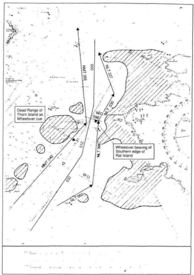
Often such wheel-over positions will be determined by the pilot using his own judgement, based upon experience.
Planned wheel-over positions should be determined from the Ship's manoeuvring data and marked on the chart. Suitable visual and radar cues should then be chosen to determine when the ship is at the wheelover position. The best cues for large alterations of course consist of parallel indexes or bearings parallel to the new track, whereas for small alterations a near beam bearing is often better.
Even when the pilot has the conn, the wheel-over position should be shown on the chart so that the OOW will be aware of its imminence and importance.
Diagram 4 shows the wheel over position using two separate methods of monitoring. At the course alteration from 032 ° to 012 ° the wheel-over position is achieved when Thorn Island is ahead at 1.31 miles (known as the dead range). At the course alteration from 012° to 000 ° the wheel-over position is achieved when the southern edge of Rat Island bears 096°.
PARALLEL INDEXING
ARPA MAPPING
WAYPOINTS
The parallel index (PI) is useful method of monitoring cross-track tendency in both poor and good visibility. It is a good practice to mark the planned PI on the chart inconspicuously at the planning stage. Like any radar technique, it is advisable to practise using PIs extensively in good visibility before placing total reliance on them when thick weather makes visual navigation methods impossible.
This simple and effective method of continuously monitoring a ship's progress is carried out by observing the movement of the echo of a radar-conspicuous navigation mark with respect to track lines previously prepared on the reflection plotter or by using ARPA index lines. It is most effective when the radar is in the north-up, relative motion mode.
A fixed radar target, such as a lighthouse or a headland, will apparently track past the own ship, depicted as being at the centre of the screen, as a line parallel and opposite to the ship's ground track. Any cross track tendency, such as may be caused by a tidal stream, will become apparent by the target moving off the parallel line.
The parallel index may also be used to monitor other events—e.g., wheel-over position. In this case the range and bearing of the target at the wheel-over point is marked on the PI. This also allows for a distance countdown to be made.
Many modern ARPAs have the facility to generate synthetic maps which can be stored in a retrieval system. In some instances, such maps may be stabilised through an electronic navigational system, but such facilities should be used in addition to and not to the exclusion of other systems.
A waypoint is a position, shown on the chart, where a planned change of status will occur. It will often be a change of course but may also be an event such as:
1.End or beginning of sea passage.
2.Change of speed.
DIAG. 4. COURSE ALTERATIONS AND WHEEL-OVER POSITIONS
Crown copyright. Reproduced from Admiralty Chart 3274 with the permission of the Hydrographer of the Navy
DIAG. 5. PARALLEL INDEXING
Crown copyright. Reproduced from Admiralty Chart 3274 with the permission of the Hydrographer of the Navy
3.Pilot embarkation point.
4.Anchor stations etc.
Waypoints may also be used as useful reference points to determine the ship's passage time and whether or not a schedule is being maintained, particularly when they have been included in the appropriate electronic navigational system. Where an electronic navaid which stores waypoint information is in use, care should be taken to ensure that waypoint designators remain uniform throughout the plan.
ABORTS & CONTINGENCIES |
No matter how well planned and conducted a passage may be, there may come |
|
|
the time when, due to a change in circumstances, the planned passage will have |
|
|
to be abandoned. |
|
ABORTS |
When approaching constrained waters the ship may be in a position beyond |
|
|
which it will not be possible to do other than proceed. Termed the point of no |
|
|
return, it will be the position where the ship enters water so narrow that there is |
|
|
no room to return or where it is not possible to retrace the track due to a falling |
|
|
fide and insufficient UKC. |
|
|
Whatever the reason, the plan must take into account the point of no return and |
|
|
the fact that thereafter the ship is committed. A position needs to be drawn on |
|
|
the chart showing the last point at which the passage can be aborted and the ship |
|
|
not commit herself. The position of the abort point will vary with the |
|
|
circumstances prevailing—e.g., water availability, speed, turning circle, etc.— |
|
|
but it must be clearly shown, as must a subsequent planned track to safe water. |
|
|
The reasons for not proceeding and deciding to abort will vary according to the |
|
|
circumstances but may include: |
|
|
1. |
Deviation from approach line. |
|
2. |
Machinery failure or malfunction. |
|
3. |
Instrument failure or malfunction. |
|
4. |
Non availability of tugs or berth. |
|
5. |
Dangerous situations ashore or in the harbour. |
|
6. |
Any situation where it is deemed unsafe to proceed. |
CONTINGENCIES |
Having passed the abort position and point of no return, the bridge team still |
|
|
needs to be aware that events may not go as planned and that the ship may have |
|
|
to take emergency action. Contingency plans will have been made at the |
|
|
planning stage and clearly shown on the chart, so that the OOW does not have to |
|
|
spend time looking for and planning safe action when his duties require him to |
|
|
be elsewhere. |
|
|
Contingency planning will include: |
|
|
1. |
Alternative routes. |
|
2. |
Safe anchorages. |
|
3. |
Waiting areas. |
|
4. |
Emergency berths. |
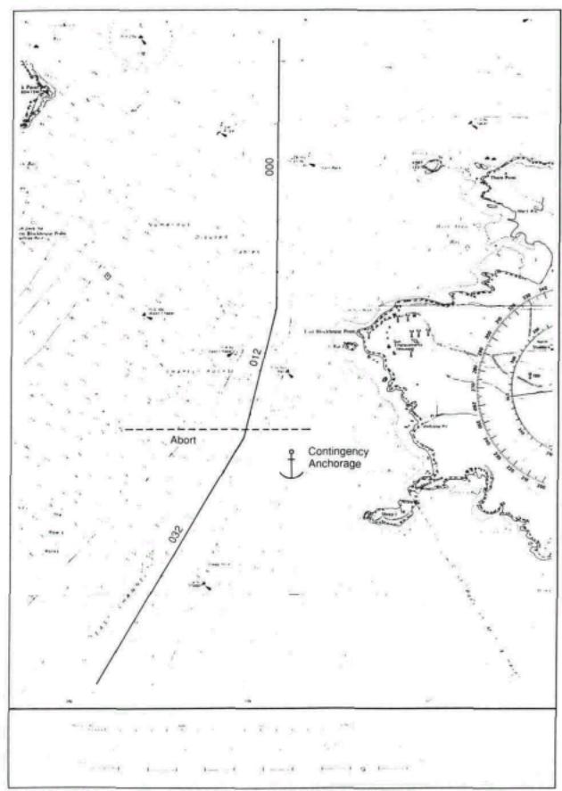
DIAG. 6. ABORTS AND CONTINGENCIES
Crown copyright. Reproduced from Admiralty Chart 3274 with the permission of the Hydrographer of the Navy
POSITION FIXING
PRIMARY AND SECONDARY POSITION FIXING
RADAR CONSPICUOUS OBJECTS & VISUAL NAVAIDS
LANDFALL LIGHTS
It will be appreciated that emergency action may take the ship into areas where it is constrained by draught, in which case speed will have to be reduced; or tidally constrained, whereby it can only enter such areas within the tidal window. Such constraints must be clearly shown.
Having drawn no-go areas, the margins of safety and the track to be followed, the planning should now be concentrated on ensuring that the ship follows the planned track and that nothing will occur which is unexpected or cannot be corrected.
A variety of position fixing methods is now available but it must not be assumed that any one of these methods will suit all circumstances.
In order that the position fixing process is smooth, uneventful and clearly understood by all concerned, the passage plan will include information as to which fixing methods are to be used, which one is to be considered the primary method and which one(s) are to be used as backup or secondary. For example, whilst the ship is out of sight of land it may well be that the GPS is the primary system with Loran C as the secondary or back-up system. As the ship approaches the coast, the GPS will still be providing the primary fixing, the Loran C becoming less important and the radar fix confirming the GPS fix.
Eventually the Loran C, although running, will become redundant and more reliance placed on the radar fix with the GPS taking the secondary role. In enclosed waters the GPS position may become inappropriate and position fixing depend upon radar and visual methods. It is not possible to determine an invariable system; it depends upon the equipment available and the circumstances of the individual case. The important thing is that all concerned are aware that a system is in operation and that it should be followed as far as is practicable.
In order to reduce the workload while navigating in coastal waters, the navigator will have determined and planned his primary and secondary methods of fixing. To reduce further the OOWs workload the navigator will have studied his chart at the planning stage and decided which radar conspicuous marks and visual aids are to be used at each stage of the passage.
When making a landfall it should not be necessary for the OOW to have to examine the chart minutely to find which lights will be seen first. These should have been clearly shown on the chart so that the OOW can concentrate on actually looking for the light concerned, not looking on the chart trying to discover which lights should be visible.
The same applies when passing along a coastline or through constrained waters. All lights shown on a chart look similar and need to be studied to determine their individual significance. This needs to be done at the planning stage, not the operational stage when the OOW concerned may be too busy to spend time behind the chart table.
RADAR TARGETS
BUOYAGE
FIX FREQUENCY
FIX REGULARITY
Similarly with radar targets—a little time spent at the planning stage will soon determine which are the targets to look for and use; a steep-to islet is going to be more reliable than a rock awash.
Highlight on the chart Racons and other radar conspicuous object which will be used for position fixing. Highlight visual navaids as appropriate, differentiating between floating and fixed navaids and high-powered and low-powered lights.
Whenever buoys or other floating navmarks are being used as position fixing aids, their own position must be first checked and confirmed that they are as shown on the chart. In situations where buoy fixing is critical, such positions can be predetermined at the planning stage by noting their range and bearing from a known fixed object.
Irrespective of the method of fixing to be used. it is necessary to establish the required frequency of the fixing. Quite obviously, this is going to depend on the circumstances prevailing; a ship close to danger will need to be fixed much more frequently than one in the open sea.
As a guideline it is suggested that fixing should be at time period such that it is not possible for a ship to be put into danger between fixes. If it is not possible to fix the position on the chart at such a frequency (fixes at intervals of less than three minutes can be very demanding) then alternative primary navigation methods—for example, parallel indexing —should be considered.
Having established the fix frequency, it is good practice to ensure that fixes are in fact made at that frequency, not as and when the OOW thinks fit. The only exception to this will be if the OOW has other priorities with which to contend— e.g., course alterations for traffic or approaching a critical wheel-over position. In this latter case, the ship's position should have been established immediately before the turn and again, as soon as possible, on completion.
ADDITIONAL INFORMATION Although not essential to the safety of the ship, a lot of additional information can be shown on the plan which, by reminding the OOW of his obligations or
reminding him to make certain preparations, will make the execution of the voyage simpler. Such information will include:
REPORTING POINTS
ANCHOR CLEARANCE
PILOT BOARDING AREA
TUG ENGAGEMENT
TRAFFIC AREAS
Reporting to the relevant authority as and where required can only make the vessel's routeing safer. Such reporting may also be compulsory.
Positions where anchor stations need to be called and the anchors cleared should be shown in order not to be overlooked.
Timely preparation of the pilot ladder and warning to involved personnel to stand by as required.
Reminder to OOW to call the crew necessary to secure tugs.
Areas where heavy traffic or where occasionally heavy traffic—e.g., ferries or fishing boats may be met.
Safe navigation of the ship does not only require fixing the position of the ship on the chart at regular intervals. The OOW needs to be constantly updating himself regarding the position of the ship relative to the required track and its tendency to increase or decrease its deviation from track. Although the regular fixing will give this information there are Other, less obvious ways of obtaining such information often requiring little input other than just observing natural features. Many of these can be planned in advance and marked on the chart:
TRANSITS (RANGES)
COMPASS ERROR
LEADING LINES
Transits (known as ranges in the USA)—i.e., the line on the chart upon which an observer would see two identifiable objects in line—can be used to give the OOW a quick indication of his position. Although it is only a single position line its advantage is that it requires no use of instruments but can be seen by eye. For extreme accuracy the distance between the observer and the nearer object should be no more than 3 times the distance between the objects observed, though transits of greater than this distance can be used to advantage.
Transits are sometimes printed on charts of inshore waters. but good use can be made of natural and clearly identifiable transits found at the planning stage and drawn on the chart.
Transits can also be used as a cue for a pre-arranged action to be taken—e.g., wheel-over, — or as a reminder than an event is about to occur.
Transits may be used to determine gyro and magnetic compass errors by comparing charted and observed bearings.
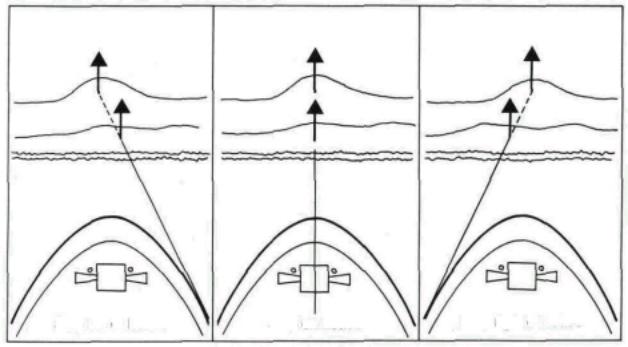
Leading lines are often shown on charts. In this case the transit printed on the chart is a track line to be followed to ensure that the ship passes clear of danger. By observing that the leads are in line the navigator is assured that his ship is on the planned track.
Ship left of Leads |
Ship on Leads |
Ship right of Leads |
LEADING LINE
CLEARING MARKS
HEAD MARK
Clearing marks can be used to ensure that a ship is remaining within a safe area or is not approaching a danger. In diagram 7 the clearing mark is shown so that as long as the Western edge of Rat Island remains open of and to the left of Sheep Buoy then the ship is making a safe approach with reference to that side of the channel.
Often a ship is required to follow a track in narrow waters without the benefit of a leading line. In this case a suitable head marker should be selected. This should be a readily identifiable conspicuous object shown on the chart, which lies on the projection of the required track at that part of the passage. As long as the bearing of the head marker, corrected for errors and preferably taken with a centre line repeater remains constant (i.e., the same as the required track), the ship is remaining on track. It should be noted that the ship need not necessarily be heading directly at the object, only that it is on the line of the required track. In most cases the ship's head will need to be offset to allow for tide or leeway.
CLEARING BEARINGS
RANGE OF LIGHTS
GEOGRAPHICAL RANGE
In the event that no clearing marks are available a single identifiable charted object may be similarly used. In diagram 8, as the ship makes the approach track of 032° T it will remain safe as long as the fort on the Western end of Thorn Island remains within the range of bearings 028 ° T - 042 ° T. These clearing bearings should be shown on the chart as NLT 028 ° T and NMT 042 ° T (not less than / not more than).
Observing clearing bearings and clearing marks cannot be considered to be 'fixing' the ship but can assist the OOW in ensuring that his ship is not standing into danger. Similarly, using dipping distances, whilst not being considered to be an accurate fix, can make the OOW more aware that he is approaching danger.
The maximum range at which a navigational light can be seen depends upon three separate factors:
1.The combined height of eye of the observer and the elevation of the light.
2.The intensity of the light.
3.The clarity of the atmosphere.
The greater the elevation of the light, the greater the distance at which it will be visible; equally, the greater the height of eye of the observer, the greater he will see the light. These two factors combined will give a maximum range of visibility called the geographical range and may be obtained from tables in the list of lights. In practice, this range will be severely reduced if the light observed is only low powered and therefore not capable of being seen at its geographical range.
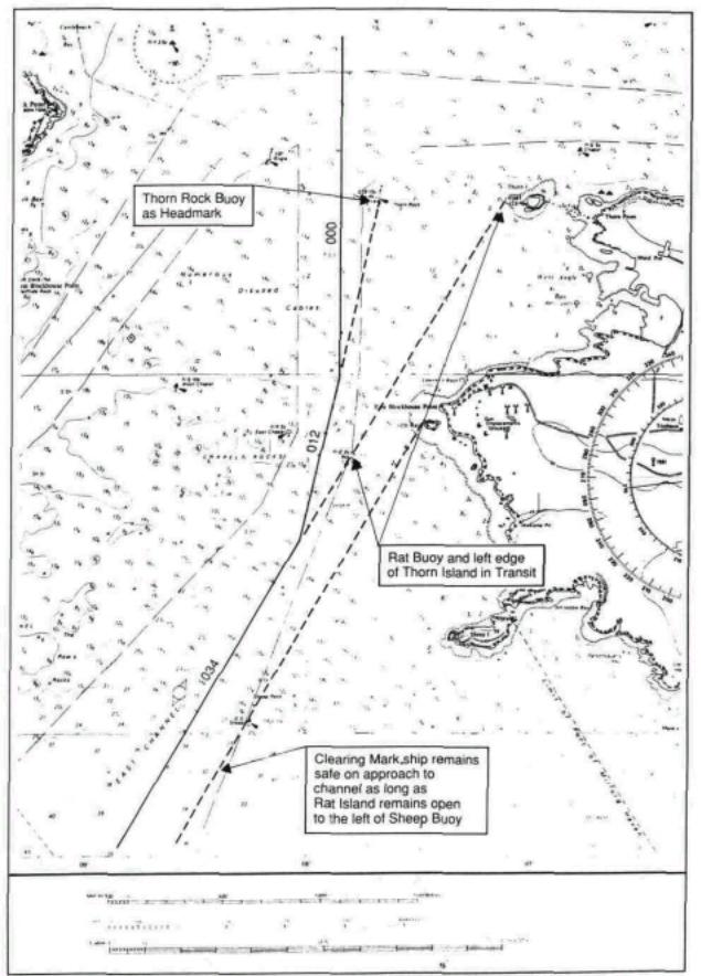
DIAG. 7. NATURAL TRANSIT, CLEARING MARKS & HEAD MARK
Crown copyright. Reproduced from Admiralty Chart 3274 with the permission of the Hydrographer of the Navy
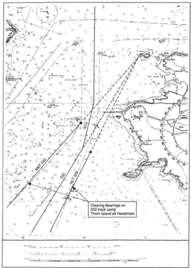
DIAG. 8. CLEARING BEARINGS
Crown copyright. Reproduced from Admiralty Chart 3274 with the permission of the Hydrographer of the Navy
LUMINOUS RANGE
NOMINAL RANGE
LANDFALL LIGHTS
This is the maximum distance at which the light can be seen and is dependent upon the intensity of the light and the atmospheric visibility prevailing. It takes no account of the height of the light or that of the observer's eye. Obviously the more intense the light, the further it will be seen, whatever the state of the atmosphere, and the appropriate table will give a good indication of how far the light can be expected to be seen.
The range shown on the chart, beside the light star. is usually the nominal range— i.e., the luminous range when meteorological visibility is 10 miles. This is not invariable, though. Some countries, such as Japan, chart the geographical range: some, such as Brazil, the geographical or nominal according to whichever is the greater. It is the navigator's responsibility to make himself aware of which range is shown and to ensure that the OOWs are also aware of this fact.
At the planning stage of the voyage, the navigator will have the opportunity to determine the maximum distance at which a landfall light should become visible. A comparison of the nominal and geographic ranges can be made and the lesser of the two selected as being the range at which the light should be seen, assuming meteorological visibility of at least 10 miles. It should be noted that only lights whose luminous range exceeds their geographical range can be considered as giving an approximate fix. In any case the arcs of maximum visibility should be drawn on the landfall chart so that the OOW is aware of the likelihood of seeing lights and which ones he should see first.
EXTREME RANGE
ECHO-SOUNDER
CHART OVERCROWDING
Approaching the coast, lights will come into view according to their height, their intensity and the ambient visibility.
Sometimes the first indications of the proximity of the coast will be powerful lights which may be seen before the radar can detect them as targets. Whilst not pretending that sighting the lights can be an accurate fix. an observation of the compass bearing at the time of sighting and plotting this with the extreme range of the light at this time will give the OOW an awareness of the proximity of danger.
In the event that a light is not sighted as expected, then the OOW will be aware that the ship is not where he anticipated it to be or that the light is unlit or obscured in cloud or that there is poor visibility between the ship and the light. The actual cause must be determined by his own judgement. The fact is that there is something not quite as it should be.
Some ships leave an echo-sounder running at all times. On ships where this is not the case, it is good practice to switch the echo-sounder on prior to a landfall being made. As in the case of a light at maximum range, whilst not providing a fix, the actual decrease in soundings will make the OOW more aware that he is approaching danger.
The information required to monitor the passage will, in many instances, be shown on the working charts. In some situations this may not be feasible, there may just be too much information needing to be shown, thus overcrowding the working area, or even blotting out certain chart details. In some cases this overcrowding can be reduced by writing the
PLANNING BOOK
CONNING NOTE BOOK
MASTER'S APPROVAL
PLAN CHANGES
required information clear of the track—e.g., on the land— and drawing attention to it by either a connecting line or a reference letter.
In any case. certain information may be better written in a planning book—e.g., times of high and low water, times of sunrise and sunset, VHF working frequencies. Where a ship uses a port regularly, the navigator may prefer to put the whole of his plan into a planning book in addition to the chart, so that it can be referred to at a later date.
Depending upon the length and complexity of the passage, or certain parts of it. it is good practice for an abbreviated edition of the plan to be made into a notebook so that the person having the conn, other than a pilot, can update himself as and when required without having to leave the conning position to look at the chart.
On completion the plan must be submitted to the Master for his approval.
All members of the bridge team will be aware that even the most thorough plan may be subject to change during the passage. It is the responsibility of the person instigating such change to ensure that changes are made with the agreement of the Master and that all other members of the team are advised of such changes.
|
Chapter 4 |
|
EXECUTING THE PLAN |
TACTICS |
The plan having been made, discussed and approved, execution of the plan now |
|
has to be determined. By this is meant the methods used to carry out the plan. |
|
including the best use of available resources. Final details will have to be |
|
confirmed when the actual timing of the passage can be ascertained. The tactics |
|
to be used to accomplish the plan can then be agreed and should include: |
ETAs for TIDE
ETA for DAYLIGHT
TRAFFIC CONDITIONS DESTINATION ETA
TIDAL STREAMS
PLAN MODIFICATION
ADDITIONAL PERSONNEL
Expected times of arrival at critical points to take advantage of favourable tidal streams.
ETAs at critical points where it is preferable to make a daylight passage or with the sun behind the ship.
Traffic conditions at focal points.
ETA at destination, particularly where there may be no advantage gained by early arrival.
Tidal stream information, obtained from the chart or tidal stream atlases, can be included in the planned passage when the time of transit of the relevant area is known. Ideally, courses to steer should be calculated prior to making the transit, though in fact, strict adherence to the planned track will actually compensate for tidal streams.
Current information can also be obtained and shown on the chart.
It must always be borne in mind that safe execution of the passage may only be achieved by modification of the plan in the case of navigational equipment becoming unreliable or inaccurate or time changes having to be made—e.g., delayed departure.
In order to achieve safe execution of the plan it may be necessary to manage the risks by utilising additional deck or engine personnel. This will include an awareness of positions at which it will be necessary:
1.To call the Master to the bridge for routine situations such as approaching the coast, passing through constrained waters, approaching the pilot station, etc.
2.To change from unattended to manned machinery space.
3.To call an extra certificated officer to the bridge.
4.To make personnel, in addition to the watchkeepers, available for bridge duties such as manning the wheel, keeping lookout, etc.
5.To make personnel, in addition to the watchkeepers, available for deck duties such as preparing pilot ladders, clearing and standing by anchors, preparing berthing equipment, engaging tugs, etc.
BRIEFING
FATIGUE
VOYAGE PREPARATION
BRIDGE PREPARATION
Before commencing the voyage there is considerable advantage to be gained by briefing all concerned. This may take place over a considerable period of time. As the actual commencement of the voyage approaches, certain specific personnel will have to be briefed so that work schedules and requirements can be planned.
In particular, any variation from the routine running of the ship—e.g., doubling of watches, anchor party requirements, etc.. must be specifically advised to involved personnel, either by the Master or the navigator.
Such briefing will require frequent updating and at different stages there will have to be rebriefing as the voyage progresses. Briefing will make individuals aware of their own part in the overall plan and contributes to their work satisfaction.
Prior to the commencement of the passage and, in certain cases, during the passage, it may be necessary for the Master to ensure that rested and unfatigued personnel are available. This could include such times as leaving port and entering very heavy traffic areas or bad weather conditions or high risk situations such as transiting a narrow strait, etc. This availability can be achieved, within the limits of the total number of persons available, by ensuring that watchkeepers of all descriptions are relieved of their duties well in advance of being required on watch in order that they may rest.
This may require changes to routine watchkeeping periods. extending certain watches or even curtailing watches, but it is at the Master's discretion and he should not hesitate to make such changes.
One of the basic principles of management is ensuring that the workplace is prepared and readied for the ensuing task. This will normally be the task of a junior officer who will prepare the bridge for sea. Such routine tasks are best achieved by the use of a checklist, but care has to be taken to ensure that this does not just mean that the checklist is ticked without the actual task being done.
At the time designated by the Master the officer responsible should prepare the bridge by:
1.Ensuring that the passage plan and supporting information is available and to hand. (It is likely that the navigating officer responsible for the construction of the passage plan will have made these items ready; nevertheless, they should still be confirmed.).
Charts should be in order, in the chart drawer and the current chart available on the chart table. It is bad practice to have more than one chart on the table at a time, as information read from one and transferred to the other may not be correct.
2.Checking that chart table equipment is in order and to hand—e.g., pens, pencils, parallel rules, compasses, dividers, note pads, scrap pads, etc.
3.Checking that ancillary watchkeeping equipment is in
order and to hand—e.g.. binoculars, azimuth rings, Aldis lamp, etc.
4.Confirming that monitoring and recording equipment— e.g., course recorder, engine movement recorder—is operational and recording paper replaced if necessary.
5.Confirming that the master gyro is fully operational and follow-ups aligned. The magnetic compass should be checked.
6.Checking that all instrument illumination lamps are operational and their light levels adjusted as required. The availability and whereabouts of spares should be checked.
7.Checking navigation and signal lights.
8.Switching on any electronic navigational equipment that has been shut down and operating mode and position confirmed.
9.Switching on and confirming the readouts of echo-sounders and logs and confirming associated recording equipment.
10.After ensuring that the scanners are clear, switching on and tuning radars and setting appropriate ranges and modes.
11.Switching on and testing control equipment—i.e., telegraphs, combinators thrusters and steering gear as appropriate.
12.Switching on and testing communications equipment both internal (telephones and portable radios) and external (VHF and MF radios, Navtex, Inmarsat and GMDSS systems as appropriate.)
13.Testing the whistle.
14.Ensuring that clear view screens and wipers are operational and that windows are clean.
15.Confirming that all clocks and recording equipment are synchronised.
16.Ensuring that the workplace is in correct order, lighting is as it should be, doors and windows open and close easily, temperature controls are set as appropriate and movable objects are in their correct place.
17.After ensuring that there is no relevant new information on the telex, fax or Navtex, advising the Master that the bridge is ready for sea.
The above list is only a general guide; each ship will have its own specific checks which have to be included. A modified version of the above should also be carried out when approaching port or any area where other than routine watchkeeping may occur.
Chapter 5
MONITORING THE SHIP'S PROGRESS
Monitoring is ensuring that the ship is following the pre-determined passage plan and is a primary function of the officer of the watch. For this, he may be alone; assisted by other ship's personnel; or acting as back up and information source to another officer having the conn.
Monitoring consists of following a series of functions, analysing the results and taking action based upon such analysis.
FIXING METHOD |
The first requirement of monitoring is to establish the position of the ship. This |
|
may be done by a variety of methods, ranging from the very basic three bearing |
|
lines, through a more technically sophisticated use of radar ranges/bearings, to |
|
instant readout of one of the electronic position fixing systems—e.g., Decca, |
|
Loran or GPS. The result, though, is always the same. However the fix has been |
|
derived, you finish up with no more than a position. It is how this information is |
|
used that is important. |
VISUAL BEARINGS
FREQUENCY
REGULARITY
ESTIMATED POSITION
As stated above, fixing methods vary. Basic fixing consists of more than one position line obtained from taking bearings using an azimuth ring on a compass. Gyro or magnetic, the bearings are corrected to true, drawn on the chart and the position shown. Three position lines are the minimum required to ensure accuracy.
Poor visibility or lack of definable visual objects may prevent a three-bearing fix being made. In this case radar-derived ranges (distances) may be included in the fix and under some circumstances make up the whole of the fix. In any case a mixture of visual or radar bearings and radar ranges is acceptable. Other methods may be used—e.g., running fixes (which may be inaccurate as they depend on an element of DR) sextant angles, etc.—but these are seldom used on modem ships. Any good chartwork text book will give a wide range of less-used fixing methods.
Electronic position fixing may also be used, particularly where there are no shorebased objects to be observed and the radar coastline is indistinct. Whilst these systems appear to be infallible the operator needs to have a good understanding of the principles and failings of the electronic system being used, in order to avoid a false sense of security,
Fix frequency will have been determined at the planning stage. Even so, this may have to be revised; always bearing in mind the minimum frequency is such that the ship cannot be allowed to get into danger between fixes.
Fixing needs not only to be accurate and sufficiently frequent, it also needs to be regular.
Regular fixing also allows a fix to be additionally checked. Each time a position has been fixed, it is good practice to estimate the position that the ship should have reached at the next fix. Providing fixing is being carried out at regular intervals this can easily be picked off as the distance between the present and the previous fix and checked against the anticipated speed. If the next fix coincides with the estimated
|
position (EP), then this acts as an additional check that the ship is maintaining its |
|
track and speed. |
|
Should the fix not coincide with the EP, then the OOW is aware that something |
|
is either wrong with the obtained position or some external influence has affected |
|
the ship. The first action is to check the EP, then check the fix. If they are both |
|
correct then something is influencing the ship; either the course being steered is |
|
not the one required or the engine revolutions have changed. If both these |
|
features are in order then some external influence is affecting the ship, either the |
|
wind has changed direction or strength or the tidal stream has changed. The |
|
OOW is immediately aware that something is influencing the ship and can take |
|
immediate action to correct it. |
SOUNDINGS |
It is also good practice to observe the echo-sounder at the same time as fixing |
|
and writing this reading on the chart beside the fix. If the observed reading is not |
|
the same as that expected from the chart then the OOW is immediately aware |
|
that something is not well. It may be that the chart is wrong; it may be that the |
|
ship is standing into danger. |
CROSS TRACK ERROR |
Having fixed the position the OOW will be aware of whether or not the ship is |
|
following the planned track and whether or not the ship will be at the next |
|
waypoint at the expected time. If the ship is deviating from the planned track he |
|
must determine whether or not such deviation will cause the ship to stand into |
|
danger and what action he should take to remedy the situation. Apart from |
|
deviating from track to avoid an unplanned hazard such as an approaching ship, |
|
there is seldom justification not to correct the deviation and get the ship back |
|
onto the planned track. The OOW must use his judgement as to how much he |
|
needs to alter course to return to track, bearing in mind that even when he has |
|
returned to the planned track he will need to leave some of the course correction |
|
on in order to compensate the cause of the earlier deviation. |
INTERNATIONAL REGULATIONS FOR PREVENTING COLLISIONS AT SEA
Irrespective of the planned passage, no ship can avoid conforming with requirements of the 'Rule of the Road'. These rules are quite clear, are internationally accepted and understood by most OOWs.
Rule 16 states: 'Every vessel which is directed to keep out of the way of another vessel shall, so far as possible, take early and substantial action to keep well clear.'
Despite the requirement to maintain track. Rule 8 makes it quite clear that the give-way ship must keep clear, either by altering course or if this is impossible then by reducing speed, or a combination of both these factors. Proper planning will have ensured that the ship will never be in a situation where such action cannot be taken.
In areas of heavy traffic and proximity of dangers, the person having the conn will have to hold a delicate balance of other-ship avoidance and planned track maintenance. The priority will be to avoid collision, but not at the expense of a grounding.
NON-NAVIGATIONAL EMERGENCIES
TIME MANAGEMENT
Similarly, the bridge team must never allow the reaction to an emergency situation to so dominate their reaction that the ship is potentially hazarded by diverting into an area of high danger. Again, the planning should have allowed for such contingencies but even the best plan cannot allow for every conceivable situation. Situational awareness and careful assessment of the situation, coupled with principles of bridge team management will help prevent a bad situation compounding and becoming worse.
In the event that the ship is ahead of or behind the planned ETA at the next waypoint. the OOW must use his judgement as to whether he adjusts the speed or not. In some instances, as for example when it is imperative that the ship's ETA is critical to make a tide, then ETAs have to be adhered to.
In either of the instances cited above, it will be the practice of the ship or at the OOWs discretion as to whether he advises the Master.
LOOKOUT |
The |
OOWs situational awareness will be improved by both |
the structured |
|
|
management of the team and his own self-discipline ensuring that he keeps a good |
|||
|
professional watch. This will include his confirming that a good |
lookout is kept. |
||
|
A good |
lookout does not just mean that he personally keeps |
a good visual |
|
|
lookout of the ship's surroundings. |
|
||
|
Rule 5 of the International Regulations for Preventing Collisions at Sea (1972, |
|||
|
ratified 1977) states: |
|
||
|
Every vessel shall at all times maintain a proper lookout by sight and hearing as |
|||
|
well as by all available means appropriate in the prevailing circumstances and |
|||
|
conditions so as to make a full appraisal of the situation and of the risk of |
|||
|
collision. |
|
||
|
Though specifically addressing collision the above-quoted rule also applies if the |
|||
|
OOW is to maintain his situational awareness. The keeping of an efficient |
|||
|
lookout needs to be interpreted in its fullest sense and the OOW needs to be aware |
|||
|
that |
lookout includes the following items: |
|
|
|
1. |
A |
constant and continuous all-round visual lookout enabling a full |
|
|
|
understanding of the current situation and the proximity of dangers, other |
||
|
|
ships and navigation marks to be maintained. |
|
|
In some instances, particularly poor visibility, radar will give a better picture of the ship's environment than actual visual observation. However, unless the OOW has considerable experience of comparing the radar picture with the visual scene he cannot automatically interpret his radar picture. In any case, the visual scene is the real scene not an electronic version of reality and the OOW who frequently observes the scene outside the windows will have a better understanding of and feel for the world around him.
2.Visual observation will also give an instant update of environmental changes, particularly visibility and wind.
3.Visual observation of the compass bearing of an encroaching other-ship will quickly show whether or not its bearing is changing and whether or not it needs to be considered a danger.
4.Visual observation of characteristics of lights is the only way of positively identifying them and thus increases the OOWs situational awareness.
5.The lookout will also include the routine monitoring of ship control and alarm systems—e.g., regularly comparing standard and gyro compasses and that the correct course is being steered.
6.Electronic aids should not be overlooked or ignored, under any circumstances, but it should be borne in mind that echo-sounders, radars, etc., are aids to navigation, not merely single means of navigation.
7.Also included in the concept of lookout should be the advantageous use of VHF. Judicious monitoring of the appropriate channels may allow the ship to be aware of situations arising long before it is actually in the affected area.
8.A routine should be established for major course alterations including:
a.Checking astern prior to altering.
b.Checking, both visually and by radar, along the bearing of the new track.
The OOW's situational awareness will also be enhanced by his observation of his environment using all available means, not just limiting himself to the routine of fixing and correcting as described above.
UNDER KEEL CLEARANCE
WAYPOINTS
Routine observation of the echo-sounder should become one of the procedures of the watch.
Besides being points noted on the chart where a change of status or an event will occur, waypoints are also good indicators of whether the ship is on time or not. If not, then something has occurred or is occurring which has affected the passage and the OOW will take steps to correct this occurrence.
TRANSITS (RANGES)
LEADING LINES
Transits are often important navigational features, they can. for example, be used to cue decisions such as a wheel-over. but can also be used in a more passive role. The OOW can use a transit to confirm that the ship is on schedule or that it is remaining on track, particularly when this occurs after an alteration. Of itself, the confirming transit may be no more than a minor occurrence but it will help the observant OOW confirm in his own mind that all is well and as it should be.
Leading lines—i.e., the transit of two readily identifiable land-based marks on the extension of the required ground track and usually shown on the chart—are used to ensure that the ship is safely on the required track.
NATURAL LEADING LINES
CLEARING MARKS & BEARINGS
RISING/DIPPING
DISTANCES
LIGHT SECTORS
In some instances the OOW may be able to pick up informal leading lines—e.g., a navmark in line with an end of land which will confirm that the vessel is on track.
Observation of a head mark and a quick mental calculation will give an indication of the distance that the ship has deviated from her track.
Required brg. ~ observed brg. x dist from object (Miles) = dist off track in cables 6
Alternatively, the off-track distance can be readily evaluated by looking down the required bearing and estimating the distance between the headmark and where the observed bearing meets the land. Man-made features such as cars, buses and lamp posts can aid this estimate.
As described in planning, clearing marks and clearing bearings, whilst not being considered to be a definitive fix, will indicate to the OOW that his ship is remaining in safe water.
Making a landfall or running along a coastline, observing rising and dipping distances of powerful lights and marking this on the chart with the observed bearing can also help assure the OOW that the ship is in the anticipated position.
The changing colours of sectored lights can also be used to advantage by the OOW and in certain instances, which the OOW should be very aware of. will indicate that the ship is standing into danger. On occasion the flickering sector change can virtually be used as a bearing. Care needs to be taken in icy weather as sectors can become indistinct.
Chapter 6
TEAMWORK
IMO Resolution 285 requires that the OOW 'ensures that an efficient lookout is maintained' but concedes that
'there may be circumstances in which the officer of the watch can safely be the sole lookout in daylight.'
However: 'When the officer of the watch is acting as the sole lookout he must not hesitate to summon assistance to the bridge, and when for any reason he is unable to give his undivided attention to the lookout such assistance must be immediately available.' (Annex B 2.) It is normal practice to have the uncertificated watchkeeper working in the vicinity of the bridge where he can be called should he be required. At night the lookout is normally on the bridge carrying out his exclusive lookout duties.
Under certain conditions the OOW may be the only person actively engaged in the navigation of the ship. The steering may be in automatic and the lookout engaged in duties around the bridge area. There is no apparent call for teamwork; the OOW will be personally responsible for all aspects of safe navigation. Nevertheless, he will be required to work within a framework of standing and specific orders so that the Master will be confident that the watch is being kept to his, and the company's, standards.
The single watchkeeper status may change at short notice. If the OOW becomes engaged in duties which require him to forgo his obligations as lookout then he will have to call his unlicensed watchstander to take that role. Here we have the first basics of teamwork.
It is the responsibility of the OOW to ensure that the seaman assigned watchkeeping duties:
1.Has been properly instructed in lookout duties as to what is expected of him.
2.Knows how to report observations.
3.Is adequately clothed and protected from the weather.
4.Is relieved as frequently as necessary.
The watchkeeping officer may require a man on the wheel in addition to the lookout. It is the responsibility of the OOW to see that the vessel is safely and efficiently steered.
We are now in a situation requiring a fair amount of organisation and cooperation. The watch officer still has the responsibility for the watch but has to use and rely upon the assistance of two other people. It is his responsibility to ensure that they are aware of their duties and carry them out in a manner which will enhance the standard of the watch. Although neither person, in this case, should find the duties particularly onerous or difficult, the watch officer still needs to ensure that orders are correctly followed—e.g., helm orders are complied with as required, not as the helmsman thinks fit.
Under certain circumstances the OOW may find it is necessary to call the Master to the bridge. This may be because the preplanning requires the presence of the Master on the bridge or the Master's standing or night orders have required him to be called under the developing circumstances or because the OOW has realised that the situation needs the experience and expertise of the Master.
Calling the Master to the bridge will not transfer the conn from the watch officer to the master. Until such time as the Master actually declares that he has the conn the OOW must still carry out his duties as he was prior to the Master's arrival. Once the Master has taken the conn, and the event logged, then the watch officer moves into a supportive role. but is still responsible for the actions of his watch members.
It is now necessary to define the role of the individual team members. Quite obviously this will to a large extent depend upon the individuals involved and the practice of the ship, but
unless each individual's role is understood by all involved there will be overlapping or a possible ignoring of certain functions. Teamwork will depend upon the following role suggestions being carried out.
The Master controls movement of the vessel in accordance with the Rule of the Road and recommended traffic schemes, regulates the course and speed and supervises the safe navigation of the vessel and co-ordinates and supervises the overall watch organisation.
The Watch officer continues to navigate the ship reporting relevant information to the Master, ensuring that such information is acknowledged. He will fix the vessel and advise the conn of the position and other information. He will monitor the execution of helm and engine orders, co-ordinate all internal and external communications, record all required entries in logbooks and perform other duties as required by the Master.
The lookout and helmsman will still be carrying out their duties, as above.
Under certain circumstances, the Master may consider it necessary to have the support of two navigating officers— one as OOW, the other as backup. The Master's responsibilities will be as above, but the responsibilities of the two officers will require careful definition.
It is obvious that a scenario requiring two watch officers supporting the Master will indicate that the ship is in a very high risk situation.
Probable factors will be:
1.Narrow margins of safety requiring very careful track maintenance.
2.Reduced underkeel clearance.
3.Heavy traffic.
4.Poor visibility; or any combination of similar factors.
The OOW will still carry out his duties as defined above and be generally responsible for the normal running of the watch.
The additional officer's role will be to provide the Master with radar-based traffic information and to giving general backup to the OOW on the chart. This will include providing the chart with navigational information as required, confirming important navigational decisions and coping with both internal and external communications.
It is difficult to establish hard and fast rules about how the tasks of the bridge team should be distributed. It will depend upon the abilities and characters of the personnel involved, the circumstances requiring the additional personnel involvement and the layout of the bridge. The important thing to bear in mind is that each member of the team knows the role that he is required to carry out and the roles of other members of the team. As stated above this will preclude unnecessary duplication of tasks and, more importantly, ensure that other tasks are not ignored or overlooked.