

Linear Engine / 990921
.pdf
|
60 00 |
|
|
|
|
|
|
|
|
|
|
|
50 00 |
|
|
|
|
|
|
|
|
|
|
|
40 00 |
|
|
|
|
|
|
|
|
|
|
[kPa] |
|
|
|
|
|
|
|
|
|
|
|
Pressure |
30 00 |
|
|
|
|
|
|
|
|
|
|
|
|
|
|
|
|
|
|
|
|
|
|
|
20 00 |
|
|
|
|
|
|
|
|
|
|
|
10 00 |
|
|
|
|
|
|
|
|
|
|
|
0 |
|
|
|
|
|
|
|
|
|
|
|
0 |
5 |
10 |
15 |
20 |
25 |
30 |
35 |
40 |
45 |
50 |
|
|
|
|
|
|
D is p lac em en t [m m ] |
|
|
|
|
|
Figure 2. Experimental Data derived from the Operation of the Prototype Linear Engine-Alternator Combination [12]
Pressure [kPa]
6000 |
|
|
|
|
|
|
|
|
|
|
|
|
|
Cd=0.00585 s |
|
|
|
|
|
|
|
5000 |
|
|
freq=29.2 Hz |
|
|
|
|
|
|
|
|
|
Heat input Q=25 J/stroke |
|
|
|
|
|
|||
|
|
|
|
|
|
|
|
|||
|
|
|
The spark occurs at X=45.35 m m |
|
|
|
|
|
||
4000 |
|
|
|
|
|
|
|
|
|
|
3000 |
|
|
|
|
|
|
|
|
|
|
2000 |
|
|
|
|
|
|
|
|
|
|
1000 |
|
|
|
|
|
|
|
|
|
|
0 |
|
|
|
|
|
|
|
|
|
|
0 |
5 |
10 |
15 |
20 |
25 |
30 |
35 |
40 |
45 |
50 |
|
|
|
|
|
Displacem ent [m m ] |
|
|
|
|
|
Figure 3. In-Cylinder Pressure vs. Piston Assembly Displacement for a Constant Load (Case I)
By concentrating the load in the middle of the stroke (corresponding to lower values of the shape factor k), the velocity profile rotates clockwise in the velocity-displace- ment domain. In this case the peak pressure has a lower value and the frequency and the engine stroke decrease correspondingly.
CONCLUSIONS
A numerical model of a spark-ignited two-stroke cycle linear engine-alternator combination has been developed and validated using experimental data from the operation
of a prototype unit. The simulations were used to show the effect of the total heat input, the combustion duration, the reciprocating mass and the load on the operation of this engine-alternator combination. The experimental testing performed previously on the linear engine [12] showed that the linear alternator introduces a load that has a roughly sinusoidal shape throughout the stroke – here considered to be of second order (corresponding to k=0 in Figure 9). Using this load profile, a sensitivity analysis was performed to determine the influence upon the engine operation of variation in one or more parameters.
9

|
16 00 0 |
|
|
|
|
|
|
|
|
|
|
|
|
|
|
|
|
Q =2 5 J/stro ke |
|
|
C d=0 .0 03 85 s |
|
|
|
|
|
|
|
|
|
|
fre q=3 7.1 H z |
|
|
|
|
|
|
|
|
|
|
|
|
|
|
|
|
14 00 0 |
|
|
|
|
|
|
|
|
|
|
|
|
|
|
|
|
|
|
|
C d=0 .0 04 85 s |
|
|
|
12 00 0 |
|
|
|
|
|
|
|
fre q=3 4.0 H z |
|
|
|
10 00 0 |
|
|
|
|
|
|
|
C d=0 .0 05 85 s |
|
|
[kPa] |
|
|
|
|
|
|
|
|
fre q=2 9.2 H z |
|
|
|
|
|
|
|
|
|
|
|
|
|
|
Pressure |
80 00 |
|
|
|
|
|
|
|
|
|
|
|
|
|
|
|
|
|
|
|
|
|
|
|
60 00 |
|
|
|
|
|
|
|
|
|
|
|
40 00 |
|
|
|
|
|
|
|
|
|
|
|
20 00 |
|
|
|
|
|
|
|
|
|
|
|
0 |
|
|
|
|
|
|
|
|
|
|
|
30 |
32 |
34 |
36 |
38 |
40 |
42 |
44 |
46 |
48 |
50 |
|
|
|
|
|
|
D is p lac em en t [m m ] |
|
|
|
|
|
Figure 4. In-Cylinder Pressure vs. Piston Assembly Displacement for different values of the Combustion Duration for the same Heat Input (Case I)
|
5 |
|
|
|
|
|
|
|
|
|
|
|
|
|
|
|
|
|
|
|
|
Cd=0.00385s |
|
|
4 |
|
|
|
|
|
|
|
|
Cd=0.00485s |
|
|
3 |
|
|
|
|
|
|
|
|
|
|
|
2 |
|
|
|
|
|
|
|
Cd=0.00585s |
|
|
|
|
|
|
|
|
|
|
|
|
|
|
[m/s] |
1 |
|
|
|
|
|
|
|
|
|
|
|
|
|
|
|
|
|
|
|
|
|
|
Velocity |
0 |
|
|
|
|
|
|
|
|
|
|
0 |
5 |
10 |
15 |
20 |
25 |
30 |
35 |
40 |
45 |
50 |
|
-1 |
|
|
|
|
|
|
|
|
|
|
|
|
|
|
|
|
|
|
|
|
|
|
|
|
-2 |
|
|
|
|
|
|
|
|
|
|
|
-3 |
|
|
|
|
|
|
|
|
|
|
|
-4 |
|
|
|
|
|
|
|
|
|
|
|
-5 |
|
|
|
|
|
|
|
|
|
|
|
|
|
|
|
|
Displacem ent [m m ] |
|
|
|
|
|
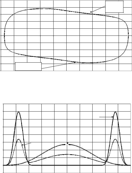
Figure 5. Piston Velocity vs. Displacement for different values of the Combustion Duration (Case I)
It was observed that the variation of the heat input influences the peak pressure, the frequency of the engine, and also the stroke length (Figures 12, 13 and 14). Variation in the combustion duration also influences the peak pressure, the frequency of the engine, and the displacement in the same manner as for the heat input variation.
By varying the mass of the moving piston assembly, the peak pressure and maximum displacement, vary proportionally. For a greater mass, the peak pressure and the
engine stroke both increase. The frequency varies in an inverse proportional relationship with the mass of the shaft.
A further observation from the numerical simulation is that, for very low piston assembly masses, the operation of the linear engine becomes possible only if the heat input is increased significantly, due to the low inertial forces associated with low piston speeds.
10

Pressure [kPa]
6 0 0 0 |
|
|
|
|
|
|
|
|
|
|
5 0 0 0 |
|
|
|
|
|
|
|
|
|
|
4 0 0 0 |
|
|
|
|
|
|
|
|
|
|
|
C d= 0 .0 05 85 s |
|
|
|
|
|
|
|
|
|
|
fre q= 3 0 .6 H z |
|
|
|
|
|
|
|
|
|
|
H ea t inp ut Q = 25 J/stro ke |
|
|
|
|
|
|
|
|
|
3 0 0 0 |
T h e sp ark occ urs a t X = 45 .35 m m |
|
|
|
|
|
|
|
|
|
2 0 0 0 |
|
|
|
|
|
|
|
|
|
|
1 0 0 0 |
|
|
|
|
|
|
|
|
|
|
0 |
|
|
|
|
|
|
|
|
|
|
0 |
5 |
1 0 |
1 5 |
2 0 |
2 5 |
3 0 |
3 5 |
4 0 |
4 5 |
5 0 |
|
|
|
|
|
D is p la c e m e n t [m m ] |
|
|
|
|
|
Figure 6. In-Cylinder Pressure vs. Displacement for a triangular shaped Load and Friction Force (Case II)
|
60 00 |
|
|
|
|
|
|
C d=0 .0 05 85 s |
|
|
|
|
|
|
|
|
|
|
|
|
|
|
|
|
|
|
|
|
|
|
|
fre q=2 9.2 H z |
|
|
|
|
|
|
|
|
|
|
|
Lo ad +Friction are |
|
|
|
|
50 00 |
|
|
|
|
|
|
trian gu la r sh ap ed |
|
|
|
|
|
|
|
|
|
|
Q = 25 J/stroke |
|
|
|
|
|
|
|
|
|
|
|
|
|
|
|
|
|
|
|
|
|
|
|
|
C d=0 .0 05 85 s |
|
|
|
|
|
|
|
|
|
|
|
fre q=3 0.6 H z |
|
|
|
|
40 00 |
|
|
|
|
|
|
Lo ad =co nstan t |
|
|
|
|
|
|
|
|
|
|
|
Friction = co nstan t |
|
|
|
[kPa] |
|
|
|
|
|
|
|
Q = 25 J/stroke |
|
|
|
|
|
|
|
|
|
|
|
|
|
|
|
Pressure |
30 00 |
|
|
|
|
|
|
|
|
|
|
|
|
|
|
|
|
|
|
|
|
|
|
|
20 00 |
|
|
|
|
|
|
|
|
|
|
|
10 00 |
|
|
|
|
|
|
|
|
|
|
|
0 |
|
|
|
|
|
|
|
|
|
|
|
0 |
5 |
10 |
15 |
20 |
25 |
30 |
35 |
40 |
45 |
50 |
|
|
|
|
|
|
D is p lac em en t [m m ] |
|
|
|
|
|
Figure 7. In-Cylinder Pressure vs. Piston Displacement for different profiles of the Friction Force and Load (for the same Combustion Process parameters and the same Heat input – Cases I and II)
Figures 13 and 14 show the in-cylinder pressure versus displacement and the velocity versus displacement respectively, for different values of the shaft mass. The results of the parametric analysis are shown in Table 4.
FUTURE WORK – Using the results of this numerical simulation, a second prototype linear engine-alternator combination is currently under development. This unit, which will employ compression ignition with a state-of- the-art direct injection diesel fueling system, is designed to produce around 10 kW of electrical power, and will be integrated into a series hybrid electric vehicle in a demonstration project.
ACKNOWLEDGMENTS
The support of the Department of Defense in funding this research is acknowledged [Grant No. DAAH04-96-1- 0328].
REFERENCES
1.Cleveland Diesel, “History and description of the free piston engine-gas turbine power”, year unkown.
2.A.F. Underwood,”GMR 4-4 Hyprex Free Piston Turbine Engine”, SAE Journal, June 1956, pp. 60-66.
11
|
5 |
|
|
|
|
|
|
|
Constant Load |
|
|
|
|
|
|
|
|
|
|
|
|
|
|
|
|
|
|
|
|
|
|
|
and Friction Force |
|
|
|
4 |
|
|
|
|
|
|
|
Load+Ff=130 N |
|
|
|
|
|
|
|
|
|
|
Q=25 J/stroke |
|
|
|
|
|
|
|
|
|
|
|
|
|
|
|
|
3 |
|
|
|
|
|
|
|
|
|
|
|
2 |
|
|
|
|
|
|
|
|
|
|
Vel |
|
|
|
|
|
|
|
|
|
|
|
oci |
|
|
|
|
|
|
|
|
|
|
|
ty |
1 |
|
|
|
|
|
|
|
|
|
|
[m/ |
|
|
|
|
|
|
|
|
|
|
|
s] |
|
|
|
|
|
|
|
|
|
|
|
|
0 |
|
|
|
|
|
|
|
|
|
|
|
0 |
5 |
10 |
15 |
20 |
25 |
30 |
35 |
40 |
45 |
50 |
|
-1 |
|
|
|
|
|
|
|
|
|
|
|
-2 |
|
|
|
|
|
|
|
|
|
|
|
-3 |
|
|
|
|
|
|
|
|
|
|
|
-4 |
|
Triangular shape of |
|
|
|
|
|
|
|
|
|
|
|
the Resultant Force of the |
|
|
|
|
|
|
|
|
|
|
|
Load and the Friction |
|
|
|
|
|
|
|
|
|
-5 |
|
Force |
|
|
|
|
|
|
|
|
|
|
|
|
|
|
|
|
|
|
|
|
|
|
|
|
|
|
Displacement [mm] |
|
|
|
|
|
Figure 8. Piston Velocity vs. Displacement for different shapes of the Friction Force and Load (for the same Combustion Process Parameters – Cases I and II)
|
800 |
|
|
|
|
|
|
|
|
|
|
|
700 |
|
|
|
|
|
|
|
|
|
|
|
|
|
|
|
|
|
|
|
k=3.55 |
|
|
|
|
|
|
|
|
|
|
|
|
|
|
|
600 |
|
|
|
|
|
|
|
|
|
|
|
|
|
|
|
|
|
|
|
|
|
|
|
500 |
|
|
|
|
|
|
|
|
|
|
Lo |
|
|
|
|
|
|
|
|
|
||
400 |
|
|
|
k=0 |
|
|
|
||||
ad |
|
|
|
|
|
|
|
|
|
|
|
[N |
|
|
|
|
|
|
|
|
|
|
|
] |
|
|
k=1.7 |
|
|
|
|
|
|
|
|
|
300 |
|
|
|
|
|
|
|
|
|
|
|
|
|
|
|
|
|
|
|
|
|
|
200
100
0 |
0 |
0.005 |
0.01 |
0.015 |
0.02 |
0.025 |
0.03 |
0.035 |
0.04 |
0.045 |
0.05 |
-100
Displacement [m]
Figure 9. More Complex Applied Load Profiles (Case III)
3.D.N. Frey, P. Klotsch and A. Egli,”The Automotive Free-Pis- ton-Turbine Engine”, SAE Transactions, Vol. 65, 1957, pp. 629-634.
4.R. Bock, U.S. Patent 4,128,083, December 5,1978,“Gas Cushion Free-Piston Type Engine”
5.R. P. Heintz, U.S. Patent 4,369,021, May 5,1980,“Free-Pis- ton Engine Pump”
6.P. A. Rittmaster et al., U.S. Patent 4,326,380, April 27,1982,“Hydraulic Engine”
7.M. D. Iliev et al., U.S. Patent 4,532,431, July 30,1985,“Method and Apparatus for Producing Electrical Energy from a Cyclic Combustion Process utilizing Coupled Pistons which Reciprocate in Unison”
8.K. A. Galitello, Jr., U.S. Patent 4,876,991, October 31,1989,“Two Stroke Cycle Engine”
9.J. F. Kos, U.S. Patent 5,002,020, March 26,1991,“Computer Optimized Hybrid Engine”
12

|
80 00 |
|
|
|
|
|
|
|
|
|
|
|
|
|
|
|
|
|
|
|
k=3 .5 |
|
|
|
70 00 |
|
|
|
|
|
|
|
|
|
|
|
|
|
|
|
|
|
|
|
k=1 .7 |
|
|
|
60 00 |
|
|
|
|
|
|
|
k=0 |
|
|
|
|
|
|
|
|
|
|
|
|
|
|
|
50 00 |
|
|
|
|
|
|
|
|
|
|
[kPa] |
|
|
|
|
|
|
|
|
|
|
|
Pressure |
40 00 |
|
|
|
|
|
|
|
|
|
|
|
|
|
|
|
|
|
|
|
|
|
|
|
30 00 |
|
|
|
|
|
|
|
|
|
|
|
20 00 |
|
|
|
|
|
|
|
|
|
|
|
10 00 |
|
|
|
|
|
|
|
|
|
|
|
0 |
|
|
|
|
|
|
|
|
|
|
|
30 |
32 |
34 |
36 |
38 |
40 |
42 |
44 |
46 |
48 |
50 |
|
|
|
|
|
|
D is p lac em en t [m m ] |
|
|
|
|
|
Figure 10. In-Cylinder Pressure vs. Piston Displacement for Different Profiles of the Load (Case III)
|
5 |
Cd=0.00585 s |
|
|
|
|
|
|
|
|
|
|
|
|
|
|
|
|
k=1.7 |
|
|
|
|
|
|
Qin=25 J/Cycle |
|
|
|
|
|
|
|
|
|
|
|
|
|
|
|
|
freq=29.7 Hz |
|
|
||
|
4 |
|
|
|
|
|
|
|
|
||
|
|
|
|
|
|
|
|
|
|
|
|
|
3 |
|
|
|
|
|
|
|
|
|
|
|
2 |
|
|
|
|
|
|
|
|
|
|
|
|
|
|
|
|
|
|
k=0 |
|
|
|
|
|
|
|
|
|
|
|
freq=32.1 Hz |
|
|
|
[m/s] |
1 |
|
|
|
|
|
|
|
|
|
|
|
|
|
|
|
|
|
|
|
|
|
|
Velocity |
0 |
|
|
|
|
|
|
|
|
|
|
0 |
5 |
10 |
15 |
20 |
25 |
30 |
35 |
40 |
45 |
50 |
|
|
|
|
|
|
|
|
|
|
|
|
|
|
-1 |
|
|
|
|
|
|
|
|
|
|
|
-2 |
|
|
|
|
|
|
|
|
|
|
|
-3 |
|
|
|
|
|
|
|
|
|
|
|
-4 |
|
k=3.5 |
|
|
|
|
|
|
|
|
|
|
|
|
|
|
|
|
|
|
|
|
|
|
|
freq=32.7 Hz |
|
|
|
|
|
|
|
|
|
-5 |
|
|
|
|
|
|
|
|
|
|
|
|
|
|
|
|
Displacem ent [m m ] |
|
|
|
|
|
Figure 11. Piston Velocity vs. Displacement for Different Load Profiles (Case III)
10.S. K. Widener and Ingram, K., “ Free-Piston Engine Linear Generator Technology Development,” Final Report, Under Contract to U.S. Army TARDEC, Mobility Technology Cen- ter-Belvoir, Fort Belvoir, Virginia, January 1995.
11.N. N. Clark, T. I. McDaniel, R. J. Atkinson, S. Nandkumar,
C.M. Atkinson, S. Petreanu and P. Famouri, " Modeling and Development of a Linear Engine", 1998 Spring Technical Conference, ASME ICE Division, Fort Lauderdale, FL.
12.N. N. Clark, T. I. McDaniel, R. J. Atkinson, S. Nandkumar,
C.M. Atkinson, S. Petreanu and P. Famouri, " Operation of a Small Bore Two-Stroke Linear Engine", 1998
13.P.G. Blair, “Design and Simulation of Two-Stroke Engines”, SAE Inc., Warrendale, Pa., 1996
14.J. B. Heywood, “Internal Combustion Engine Fundamentals”, John Wiley and Sons, New York, 1986.
15.S. Nandkumar, “Modeling of a Linear Engine”, MSME Thesis, West Virginia University, 1998
16.P. A. J. Achten, “A Review of Free-Piston Engine Concepts”, SAE 941776, 1994.
13

|
12 00 0 |
|
|
|
|
|
|
|
|
|
|
|
|
|
|
|
|
|
|
Q = 26 .5 J/stro ke |
|
|
|
|
|
|
|
|
|
|
|
fre q=3 6.1 H z |
|
|
|
|
10 00 0 |
|
|
|
|
|
|
Q = 26 .0 J/stro ke |
|
|
|
|
|
|
|
|
|
|
|
|
|
||
|
|
|
|
|
|
|
|
fre q=3 4.6 H z |
|
|
|
|
80 00 |
|
|
|
|
|
|
Q = 25 .8 J/stro ke |
|
|
|
|
|
|
|
|
|
|
|
fre q=3 3.4 H z |
|
|
|
[kPa] |
|
|
|
|
|
|
|
|
|
|
|
Pressure |
60 00 |
|
|
|
|
|
|
|
|
|
|
|
|
|
|
|
|
|
|
|
|
|
|
|
40 00 |
|
|
|
|
|
|
|
|
|
|
|
20 00 |
|
|
|
|
|
|
|
|
|
|
|
0 |
|
|
|
|
|
|
|
|
|
|
|
30 |
32 |
34 |
36 |
38 |
40 |
42 |
44 |
46 |
48 |
50 |
|
|
|
|
|
|
D is p lac em en t [m m ] |
|
|
|
|
|
Figure 12. In-Cylinder Pressure vs. Displacement for varying Heat Input (for the same load profile, k=0, Case III)
|
3 50 00 |
|
|
|
|
|
|
|
|
|
|
|
|
|
|
|
|
|
|
|
M as s=5 .3 kg |
|
|
|
3 00 00 |
|
|
|
|
|
|
|
|
|
|
|
2 50 00 |
|
|
|
|
|
|
|
|
|
|
[kPa] |
2 00 00 |
|
|
|
|
|
|
|
M as s=3 .3 kg |
|
|
|
|
|
|
|
|
|
|
|
|
||
|
|
|
|
|
|
|
|
|
|
|
|
Pressure |
1 50 00 |
|
|
|
|
|
|
|
|
|
|
|
|
|
|
|
|
|
|
|
|
|
|
|
1 00 00 |
|
|
|
|
|
|
|
|
|
|
|
|
|
|
|
|
|
|
|
M as s=2 .3 kg |
|
|
|
5 00 0 |
|
|
|
|
|
|
|
|
|
|
|
0 |
|
|
|
|
|
|
|
|
|
|
|
3 0 |
3 2 |
3 4 |
3 6 |
3 8 |
4 0 |
4 2 |
4 4 |
4 6 |
4 8 |
5 0 |
|
|
|
|
|
|
D is p la ce m e n t [m m ] |
|
|
|
|
|
Figure 13. In-Cylinder Pressure vs. Displacement for different values of the Reciprocating Mass (for the same load profile, k=0, Case III)
14

|
5 |
|
|
|
|
|
|
|
|
|
|
|
|
|
|
Mass=4.3 kg |
|
|
Mass=5.3 kg |
|
|
|
|
|
4 |
Mass=3.3 kg |
|
|
|
|
|
|
|
|
|
|
|
|
|
|
|
|
|
|
|
|
|
|
3 |
|
|
|
|
|
|
|
|
|
|
|
2 |
|
|
|
|
|
|
|
|
|
|
|
1 |
|
|
|
|
|
|
|
|
|
|
[m/s] |
0 |
|
|
|
|
|
|
|
|
|
|
Velocity |
|
|
|
|
|
|
|
|
|
|
|
0 |
5 |
10 |
15 |
20 |
25 |
30 |
35 |
40 |
45 |
50 |
|
-1 |
|
|
|
|
|
|
|
|
|
|
|
|
|
|
|
|
|
|
|
|
|
|
|
|
-2 |
|
|
|
|
|
|
|
|
|
|
|
-3 |
|
|
|
|
|
|
|
|
|
|
|
-4 |
|
|
|
|
|
|
|
|
|
|
|
-5 |
|
|
|
|
|
|
|
|
|
|
Displacement [mm]
Figure 14. Piston Velocity vs. Displacement for different values of the Reciprocating Mass (for the same load profile, k=0, Case III)
Table 4. Parametric Dependence of varying Heat Input, Combustion Duration, Applied Load, and Reciprocating Mass on Engine Performance.
− denotes proportional dependence |
PARAMETER VARIED |
|
|
|||
↓ denotes inverse proportionality |
|
|
|
|
||
|
|
|
|
|
|
|
|
|
Heat Input |
Combustion |
Frictional |
Mass of |
|
|
|
|
Duration |
Force (Load) |
Reciprocating |
|
|
|
|
|
|
Assembly |
|
EFFECT |
Frequency |
− |
↓ |
↓ |
↓ |
|
SEEN |
|
|
|
|
|
|
Peak pressure |
− |
↓ |
↓ |
− |
||
|
||||||
|
|
|
|
|
|
|
|
Velocity |
− |
↓ |
↓ |
↓ |
|
|
|
|
|
|
|
|
|
Displacement |
− |
↓ |
↓ |
− |
|
|
|
|
|
|
|
|
CONTACT |
Phone: (304) 293-4111 ext. 333 |
Dr. Chris Atkinson, Dept. of Mechanical and Aerospace |
catkinson@cemr.wvu.edu |
|
|
Engineering, West Virginia University, PO Box 6106, Mor- |
|
gantown, WV 26506, USA |
|
15