

Linear Engine / thesis
.pdf4.7Shock Absorber . . . . . . . . . . . . . . . . . . . . . . . . . . . . . . 77
4.8Power Cable, Olflex Model 891004CY . . . . . . . . . . . . . . . . . . 78
4.9Signal Cable, Olflex Model 35902 . . . . . . . . . . . . . . . . . . . . 79
4.10Isometric View of Full Assembly . . . . . . . . . . . . . . . . . . . . . 80
4.11Hidden Line View of Front of Full Assembly . . . . . . . . . . . . . . 81
4.12 |
Top View Showing Components Requiring Precision Alignment . . . |
82 |
4.13 |
Free Body Diagram of Coil . . . . . . . . . . . . . . . . . . . . . . . . |
83 |
5.1 |
High Flexibility Cable . . . . . . . . . . . . . . . . . . . . . . . . . . |
91 |
A.1 |
Bottom Plate . . . . . . . . . . . . . . . . . . . . . . . . . . . . . . . |
96 |
A.2 |
Bracket Side Pieces . . . . . . . . . . . . . . . . . . . . . . . . . . . . |
97 |
A.3 |
Breakout Box . . . . . . . . . . . . . . . . . . . . . . . . . . . . . . . |
98 |
A.4 |
Encoder Support . . . . . . . . . . . . . . . . . . . . . . . . . . . . . |
99 |
A.5 |
Yoke . . . . . . . . . . . . . . . . . . . . . . . . . . . . . . . . . . . . |
100 |
A.6 |
Bracket Joiner . . . . . . . . . . . . . . . . . . . . . . . . . . . . . . . |
101 |
A.7 |
Aluminum Plate . . . . . . . . . . . . . . . . . . . . . . . . . . . . . . |
102 |
A.8 |
Side Plates . . . . . . . . . . . . . . . . . . . . . . . . . . . . . . . . . |
103 |
A.9 |
Motion Stops . . . . . . . . . . . . . . . . . . . . . . . . . . . . . . . |
104 |
A.10 |
Cable Stress Relief . . . . . . . . . . . . . . . . . . . . . . . . . . . . |
105 |
A.11 |
Top Plate . . . . . . . . . . . . . . . . . . . . . . . . . . . . . . . . . |
106 |
xxi
xxii
Chapter 1
Introduction
This thesis documents the development of an unusual form of internal combustion engine as an experimental research apparatus. In this engine the crankshaft, which translates linear motion into rotary motion, is replaced by a linear electrical machine, which transforms linear motion into electrical power. The development is advanced to the point of demonstrating feasibility by simulation, prototyping, and the exploration of enabling technologies.
This work was carried out between 2000 and 2002 in the Department of Mechanical Engineering at Stanford University. Most of the work was performed by the author, under the supervision of Prof. Chris Gerdes, the Principal Investigator. Prof. Chris Edwards also had a significant advisory role. Doug Bourne spent a summer working on this project for an undergraduate research experience, and much of the work towards specifying components (especially the optical encoder, the cables, the bearings, and the shock absorber) was his.
This thesis is organized as a design document. The first chapter sets the work in context, by describing the ubiquity and importance of the internal combustion engine, and its application to electrical power generation by coupling it with an electrical machine. Then, the concept of the linear engine, where the crankshaft is replaced by
1
2 |
CHAPTER 1. INTRODUCTION |
a linear electrical machine, is introduced. Finally, it is stated that this thesis solves the problem of developing a linear engine to the point of feasibility.
In the second chapter, research in linear engines at West Virginia University, Sandia National Labs, and the University of Regina is reviewed for the purposes of benchmarking. A set of priorities was determined, which led to requirements that the engine employ a four stroke working cycle, feature a single unopposed piston, and be built on the same scale as existing research engines.
In the third chapter, thermodynamic, electrical, and dynamic models are integrated to implement a simulation of the linear engine in Matlab Simulink. Based on this simulation, a linear electric motor, the Aerotech BLMX-502b, was selected as the electrical machine. A prototype was built to test the linear motor.
The fourth chapter describes the selection of components to solve the problems of constraining the piston to linear motion, stopping the piston in case of a failure, and connecting the moving assembly electrically. Then a possible mechanical design for the overall system is presented.
The fifth chapter demonstrates how the work described in the previous chapters establishes feasibility and suggests directions for future work.
1.1Context
1.1.1Historical Perspective
The internal combustion engine was first realized in its modern form by Nikolaus Otto in 1867 [13, 20]. The technology spread quickly, and by World War I, the internal combustion engine was ubiquitous in both mobile and stationary applications.
With the advent of mass production, automobiles actuated by this chemical power plant entered the garages of middle class America. Around the world, fortunes were
1.1. CONTEXT |
3 |
made and lost by those who made automobiles, fuels, tires, and all the other things necessary for peoples’ new found mobility. By the 1940’s, cities like Los Angeles were transformed by new patterns of housing, labor, and even climate due to the automobile. Meanwhile, the internal combustion engine had found applications in airplanes and sea going vessels. In manufacturing and power generation, these sources of mechanical energy were also common.
Today, internal combustion engines are everywhere, and there are growing social concerns surrounding their emissions, the procurement of their fuels, and their production. Some suggest that their utility for many applications will end. However, it is clear that, for the moment, there are many applications where no other technology will be practical for some time. Therefore, research into improving the internal combustion engine is still of great social and economic importance.
1.1.2Classification of Internal Combustion Engines
There are many ways in which internal combustion engines may be classified [13, 6]. However, if we limit the scope to geometries involving reciprocating pistons (as opposed to rotary or Wankel engines), two broad distinctions are of special importance.
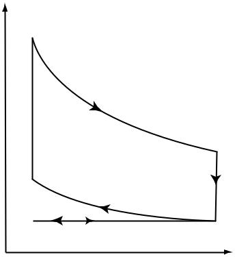
The first is the number of strokes the piston moves through to complete a full engine cycle. Virtually all automotive applications are four stroke designs. An idealized thermodynamic representation of this working cycle for gasoline engines, in terms of the pressure and volume of the combustion chamber, is shown in fig. 1.1.
According to this design, air, or an air/fuel mixture, is inducted in the first stroke, Intake. Following this, the volume of the combustion chamber is reduced, compressing the gases. At the end of the Compression stroke, near the minimum volume, the charge ignites, releasing energy. During Expansion, the combustion chamber increases in volume, converting heat energy into mechanical work. Finally, the products are expelled during the Exhaust stroke.
4 |
CHAPTER 1. INTRODUCTION |
pressure
combustion
expansion
compression
intake / exhaust
volume
Figure 1.1: Ideal Otto Cycle
More common in small and very large internal combustion engines is the two stroke working cycle. This design is similar to the four stroke cycle, except that the induction and exhaust processes occur during the transition between the Expansion and Compression strokes, rather than during separate strokes.
This usually necessitates that induction and exhaust occur simultaneously through a process called scavenging. While there are ways to implement extremely e ective scavenging, in the low weight, low cost applications in which small two strokes are typically applied, scavenging often results in wasted fuel and poor e ciency. Two stroke engines, however, enjoy a significant advantage over four stroke engines in power to weight ratios, due to the fact that they have twice as many power strokes per engine revolution.
1.1. CONTEXT |
5 |
The other major distinction to be made in classifying engine types is the manner in which the charge is ignited. In most gasoline engines, an electric spark is used to initiate combustion. A flame front starts near the spark, and propagates until the fuel is consumed. These engines can have good power to weight ratios, but their e ciency is limited by the maximum cylinder pressure, which must be kept below the threshold of autoignition during compression. Also, since torque is typically regulated by throttling the air intake, e ciency is further reduced during part load operation.
Diesel engines, however, utilize compression ignition. Because combustion is more easily initiated in this fuel, it is possible to start the combustion process at moderate cylinder pressures without a spark. Usually, in order to precisely control the timing and amount of fuel combusted, the fuel is sprayed into the combustion chamber via direct injection. These engines are often heavier and bulkier than spark ignition engines, but they are also generally more e cient due to their higher compression ratio and lower pumping losses.
1.1.3Engine Components
While internal combustion engines vary significantly in shape, size, and function, if one considers the important case of 4-stroke, spark ignition engines, there are a handful of elements common to most designs (see fig. 1.2.)
The piston moves up and down, allowing the sealed combustion chamber to change in volume. The valves open in coordination with this motion to allow gases in and out. When the charge is ready, a small region of plasma is created by the spark plug in order to initiate combustion.
The crankshaft, along with the connecting rod, converts the reciprocating linear motion of the piston into steady rotary motion. The crankshaft typically has a large amount of inertia, and thus only changes rotational velocity gradually (significant changes only occur over the course of many engine cycles.)

6 |
|
|
CHAPTER 1. INTRODUCTION |
|
spark plug |
||
|
|
|
|
|
|
|
|
exhaust |
intake |
valve |
valve |
|
combustion |
|
chamber |
|
piston |
connecting rod
crankshaft
Figure 1.2: Schematic Engine
1.1.4Generation and Electrical Machines
Many I.C. engines are used to generate electrical power for such applications as electricity in remote locations, supplying specialized electrical motors (as in hybrid electric vehicles) and emergency power. In order to accomplish this, the engine must be coupled to an electrical machine.
Electrical machines convert mechanical energy to electrical energy, or vice versa. It is feasible to build them in a variety of geometries, such as rotary or linear, and, given appropriate power control circuitry, it is feasible to operate them under steady or time varying conditions. Most electrical machines consist of two major parts: a stationary assembly, called the stator, and a moving assembly, referred to as the rotor (regardless of whether its motion is actually rotary.) A back iron, usually consisting
1.2. NEED STATEMENT |
7 |
of laminated ferrous sheets, is sometimes used to modify the behavior of the magnetic fields. Resistive losses, which result in the dissipation of electrical energy as heat, are significant factors in the e ciency of these machines.
Typically, when using an I.C. engine to generate electrical power, a rotary electrical machine is coupled to the crankshaft, and the system is designed to operate under steady conditions.
1.2Need Statement
If an engine is used solely to produce electrical power, it is not necessary to convert the reciprocating linear motion of the piston to steady rotary motion. Instead, a linear electrical machine may be coupled directly to the piston.
Such a design would open a large unexplored design space. From a machine design stand point, there are opportunities to use fewer parts and improve reliability. Because the lateral forces imposed by the crankshaft are eliminated, there are opportunities to reduce friction and achieve better sealing.
From a thermodynamic standpoint, the opportunities are even more far reaching. The piston is uncoupled from the inertia of the crankshaft, and the electrical machine may be controlled to allow for an essentially arbitrary piston position time history.
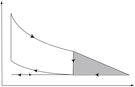
This could allow improvements to cycle e ciency such as by implementing the Atkinson cycle. The Atkinson cycle improves on the Otto cycle by delaying the opening of the exhaust valve until the pressure in the combustion chamber is near ambient (see fig. 1.3). This extracts more work from the gases, but requires a stroke which is longer during expansion and exhaust than during intake and compression.
It could also allow for novel combustion strategies such as Homogenous Charge Compression Ignition. This strategy allows gasoline engines to utilize compression ignition part of the time. Via preheating of the intake gases, intentionally retaining or
8 |
CHAPTER 1. INTRODUCTION |
pressure
combustion
expansion
compression
intake / exhaust
volume
Figure 1.3: Ideal Atkinson Cycle
reinducting exhaust residual, or, in this case, by changing to a high compression ratio, the charge undergoes a very rapid compression ignition. Under certain operating conditions, this strategy has been demonstrated to improve e ciency and reduce emissions [14, 21].
1.3Problem Statement
Such a device, in which the crankshaft has been replaced by a linear electrical machine, could be referred to as a linear engine (see fig. 1.4.) This thesis will solve the problem of developing the design of a linear engine to the point of demonstrating feasibility.
In the long term, this engine could be used in such applications as home power generation or hybrid electric vehicles. However, even if these applications do not prove commercially viable, the linear engine will have great immediate value as a laboratory tool to explore the design of internal combustion engines.