


P R E L I M I N A R Y
CLOCK GENERATION AND CONTROL
The Am186CC clocks include the general system clock (CLKOUT), USB clock, transmitter/receiver clocks for each HDLC channel, and the baud rate generator clock for UART and high-speed UART.
The SSI and the timers (Timers 0, 1, and 2) derive their clocks from the system clock.
Features
The Am186CC clocks include the following features and characteristics:
νTwo independent crystal-controlled oscillators that use external fundamental mode crystals or oscillators to generate the system input clock and the USB input clock.
νTwo independent internal PLLs, one of which generates a system clock (CLKOUT) that is 1x, 2x, or 4x the system input clock, and one that generates the 48-MHz clock required for the USB from either a 48-, 24-, or 12-MHz input.
νSingle clock source operation possible by sharing the clock source between the system and the USB.
νEach HDLC receives its clock inputs directly from the external communication clock pins (TCLK _X and RCLK_X) in all modes except in GCI mode. In GCI mode the external GCI communication clocks (TCLK_A and RCLK_A) are first converted to an internal clocking format (analogous to PCM Highway) before presentation to the HDLC. The system clock must be at least the same frequency as any HDLC clock.
–HDLC DCE mode supports clocks up to 10 MHz.
–HDLC PCM mode supports clocks up to 10 MHz.
–HDLC GCI mode supports a 1.536-MHz clock input. (System clock must be at least twice the GCI clock.)
νSSI clock (SCLK) is derived from the CPU clock, divided by 2, 4, 8, 16, 32, 64, 128, or 256.
νTimers 0 and 1 can be configured to be driven by the timer input pins (TMRIN1, TMRIN0) or at onefourth of the CPU clock. Timer 2 is driven at onefourth of the CPU clock.
νUART clock can be derived from the internal CPU clock frequency or from the UART clock (UCLK) input.
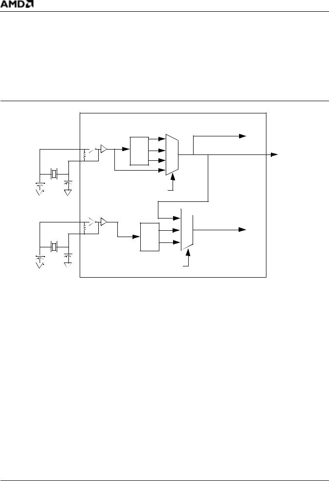
See Figure 8 on page 38 for a diagram of the basic clock generation and Figure 9 on page 39 for suggested clock frequencies and modes.
System Clock
The system PLL generates frequencies from 16 to 50 MHz. The reference for the system PLL can vary from 8 to 40 MHz, depending on the PLL mode selected and the desired system frequency (see Figure 9 on page 39). The CPU PLL modes are chosen by the state of the {CLKSEL1} and {CLKSEL2} pins during reset. For these pinstrap settings see Table 31 on page 88.
The system clock can be generated in one of two ways:
νUsing the internal PLL running at 1x, 2x, or 4x the reference clock. The reference clock can be generated from an external crystal using the integrated oscillator or an external oscillator input.
νBypassing the internal PLL. The external reference generated from either a crystal or an external oscillator input is used to generate the system clock.
USB Clock
The USB PLL provides the 48-MHz clock that is required for USB full-speed operation. This clock is divided down to provide a 12-MHz clock that supports the full-speed USB rate (12 Mbit/s). The low-speed rate of 1.5 Mbit/s is not supported. The USB PLL modes are chosen by the state of the {USBSEL1} and {USBSEL2} pins during reset. For these pinstrap settings see Table 29 on page 86.
The USB clock can be generated in one of two ways:
νUsing the CPU clock. In this mode, the CPU PLL is restricted to 48-MHz operation only.
Note: When using the CPU clock for the USB clock source, the designer must externally pull down the USBX1 input.
νUsing its own internal 48-MHz PLL. This PLL can run in 2x or 4x mode and requires a 12or 24-MHz reference that can be generated by either the integrated crystal-controlled oscillator or an external oscillator input.
Note: The system clock must be a minimum of 24 MHz when using the USB peripheral controller and its internal 48-MHz PLL.
Am186™CC Communications Controller Data Sheet |
37 |
P R E L I M I N A R Y
Clock Sharing by System and USB
The CPU and USB clocks can be generated from a single source in one of two ways:
νThe system can run at 48 MHz by using the CPU clock for the USB clock.
Note: When using the CPU clock for the USB clock source, the designer must externally pull down the USBX1 input.
νThe system can be run at 24 MHz by sharing an external clock reference (X1) with the USB (USBX1). A 12-MHz source can be used with the CPU PLL in 2x mode and the USB PLL in 4x mode, or a 24-MHz source can be used with the CPU in 1x mode and the USB in 4x mode.
|
|
Am186CC Controller |
|
|
|
1x |
CPU Clock |
|
|
|
|
|
|
2x |
CLKOUT |
X1 |
X2 |
PLL |
|
4x |
|
||
|
PLL Bypass Mode |
|
|
|
{CLKSEL2}–{CLKSEL1} |
||
|
|
|
48-MHz |
|
|
|
USB Clock |
USBX1 |
USBX2 |
|
2x |
|
|
||
|
|
PLL |
4x |
|
{USBSEL2}–{USBSEL1} |
||
|
Figure 8. |
System and USB Clock Generation |
|
38 |
Am186™CC Communications Controller Data Sheet |