

Virtuoso XL Layout Editor User Guide
Generating Your Layout with Virtuoso XL Layout Editor
3.Click OK.
4.Set the two environment variables to control how automatic abutment works in your design.
5.From the layout window, choose Create – Pick from Schematic.
The Pick from Schematic form appears.
6.In the schematic, select the instances you want to place.
7.Click on the layout where you want to place the instances.
The software places the selected instances where you click in the order that you selected them.
8.Where flight lines indicate abutment is possible, place devices so that the pins overlap. The devices are abutted.
Cloning Components
Cloning is the ability to replicate a section of the layout that is associated with a section of the schematic in such a way that the new piece of layout material can be placed at more than one location in the layout with each part preserving the hierarchical structure of the design. You can clone devices, pins, and (if selected from the layout window) interconnect structures such as wires and paths made of shapes.
Cloning differs from copying in that cloned structures include connectivity information.
The connectivity structure of the section being copied needs to match the cloned copies in
■Topological structure
■Instance master
■Instance parameters
The section of the schematic or layout that is used as a template for the cloning is called the source, and the section of the schematic that is to be implemented by copying the source is the target. The result of copying the source to implement the target structure is the clone.
Multiple layout cellviews and multiple connectivity sources can be used. Permutability is allowed for greater matching flexibility.
December 2002 |
181 |
Product Version 5.0 |

Virtuoso XL Layout Editor User Guide
Generating Your Layout with Virtuoso XL Layout Editor
Cloning
To select a section of a design from either the schematic or the layout to be used as the source for an analogous structure elsewhere in the layout, follow these steps.
1.In the schematic or layout window select the devices you want to copy.
2.To replicate a structure in the layout, select Create – Clone.
The CIW prompts you to select a connectivity source.
3.In the schematic or layout window press the Return key.
Note: You must press the Return key when you have preselected objects.
The connectivity source can be selected either from the layout cellview or the schematic or other Virtuoso XL source cellview. Use single or area selection. Use the shift key to add objects to the select list. Use the Shift key to deselect objects from the select list.
Press the Return key.
The advantage of selecting the connectivity source from the layout is that shapes can also be selected and cloned.
Note: If the structure to be cloned has been routed (has interconnects), then the structure should be selected from the layout view,(i.e both the components and the interconnects should be selected). Selecting the source from the schematic will only clone the components and their relative placement, and not the routing/ interconnects.
December 2002 |
182 |
Product Version 5.0 |
Virtuoso XL Layout Editor User Guide
Generating Your Layout with Virtuoso XL Layout Editor
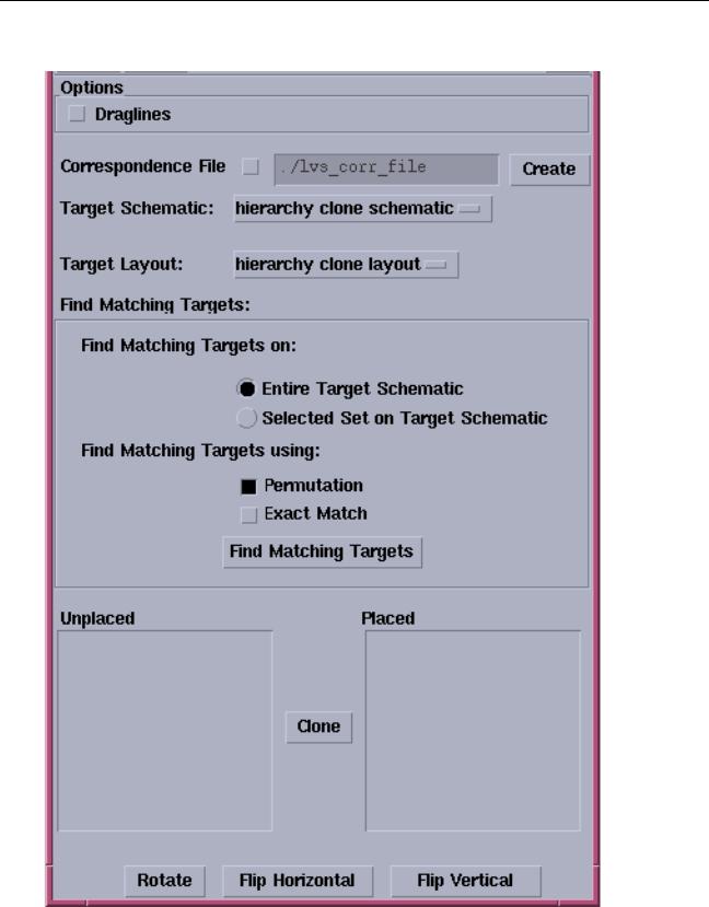
The Cloning form appears.
December 2002 |
183 |
Product Version 5.0 |

Virtuoso XL Layout Editor User Guide
Generating Your Layout with Virtuoso XL Layout Editor
Note: If the Options Displayed When Commands Start option is turned on the User
Preferences form (CIW – Options – User Preferences), then the Cloning form will automatically appear. If you do not have this option turned on then press the F3 key to open the Cloning form.
4.In the Cloning form set the Target Schematic and the Target Layout to the correct cellviews.
Note: The target structure (components and interconnects) should not exist in the layout view at the time of cloning (should be deleted prior to cloning if generated already). Otherwise the cloning command will generate message stating that the target structure is incorrectly or partially implemented.
5.To find the target matches turn on theEntire Target Schematic, Permutation and
Exact Match options.
6.Select Find Matching Targets.
7.The Unplaced devices will be listed in the Unplaced list box.
8.Select the devices from the Unplaced list box.
9.Click Clone and place the device in the layout window.
You can clone one device or a group of devices. To clone a group of devices create a cell with the devices and then clone the cell. This insures that all the cells or like circuit sections have the same layout parasitics associated with them.
10.Move the cursor to the layout window.
The outline of the layout structure follows the cursor.
11.In the Cloning form, select the placement options (Rotate, Flip Horizontal, Flip Vertical, and Draglines) that affect the placement or appearance of the clone.
12.Click in the layout to place the cloned structure where you want it. The cloned structure is placed in the layout.
13.If you selected more than one target structure, click Clone on the Cloning form and move the cursor to the layout window again to place the next target.
The outline of the layout structure follows the cursor.
Note: You cannot use structures in the layout that use many-to-one mapping as the connectivity source for cloning. If you select a many-to-one structure to use as a connectivity source, a warning appears in the CIW explaining the error and the structure is not selected
December 2002 |
184 |
Product Version 5.0 |