

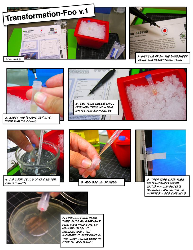
The Foo Camper’s guide to biological engineering

BBa_J45200
Banana Odor Generator
DNA
Mechanism & Function
The banana odor generator (BBa_J45200) catalyzes the conversion of the precursor isoamyl alcohol to the odor isoamyl acetate that has a banana smell. The biosynthetic device is composed of two transcriptional devices: a constitutive transcription source (BBa_R0040) and an odor enzyme generator (BBa_J45199). Odor enzyme generators produce as output an enzyme that catalyzes production of an odor from a chemical precursor.
BBa_J45200 

Component Parts
R0040 |
B0030 |
J45014 |
B0015 |
PtetR |
RBS |
ATF1 |
Term. |
Activity
|
1.2 |
|
|
|
(mM) |
1.0 |
|
|
|
0.8 |
|
|
|
|
acetate |
|
|
|
|
0.6 |
|
|
|
|
Isoamyl |
|
|
|
|
0.4 |
|
|
Culture 1 |
|
|
|
|
Culture 2 |
|
|
0.2 |
|
|
Culture 3 |
|
|
|
|
|
|
0.0 |
0.5 |
1.0 |
1.5 |
|
0.0 |
|||
|
|
Cell density (OD600nm) |
|
|
Isoamyl acetate concentration increases with cell density
Usage
Cells expressing ATF1 should be grown in the presence of isoamyl alcohol (5mM).
Chromatography
A BBa_J45200
isoamyl acetate |
octyl acetate |
indole |
|
internal standard |
|||
|
|
B TOP10
octyl acetate |
indole |
|
internal standard |
||
|
no isoamyl acetate
C Standard
octyl acetate internal standard
isoamyl acetate
High levels of isoamyl acetate are produced when the precursor isoamyl alcohol is added to the culture medium (A), unless the cellular chassis (E. coli strain TOP10) does not contain J45200 (B). The retention time of the isoamyl acetate peak from J45200 is identical to that of the pure isoamyl acetate standard (C). Most E. coli strains produce indole. Octyl acetate was used as an internal standard for all samples containing isoamyl acetate
 Reporter Devices http://partsregistry.org/Part:BBa_J45200
Registry of Standard Biological Parts |
License: Public |
|
making life better, one part at a time |
||
|
BBa_G10001
Visible Light Generator
DNA
Mechanism & Function
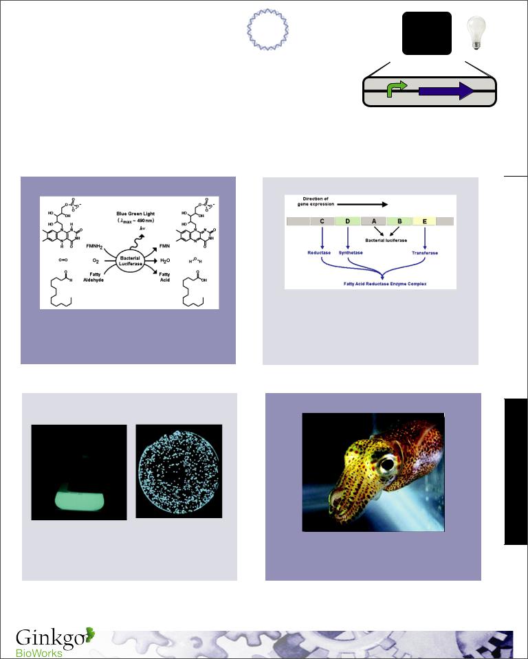
The expression of the Lux operon is controlled by a regulated operator (PLac). If used in a cell containing lac repressor (LacI) then an input such as IPTG can be used to modulate the expression of the Lux operon. When expressed this operon produces the necessary enzymes to generate the fatty aldehyde substrates as well as the luciferase enzyme that converts luciferin to visible light.
BBa_G10001 
Component Parts
PLac LuxCDABE
Reaction Mechanism |
Lux Operon |
|
The fatty acid reductase enzyme complex is |
Bacterial luciferin is a reduced riboflavin phosphate |
needed to recycle the fatty aldehyde substrate in |
the reaction and luciferase is required to catalyze |
|
(FMNH2, above) which is oxidized in association |
the reaction. No other exogenous enzymes are |
with a long-chain aldehyde, oxygen, and a |
necessary since FMNH2 is provided by the |
luciferase to produce visible light. |
native electron transport chain in E. coli. |
Usage |
Origin |
Cells expressing the lux operon are visible in |
The Lux operon was isolated from Vibrio fischeri a |
low light in liquid culture or as colonies. |
bacteria found predominantly in symbiosis with |
|
marine animals such as the bobtail squid (above). |
 Reporter Devices http://partsregistry.org/Part:BBa_G10001
|
Registry of Standard Biological Parts |
|
|
License: Unknown |
|
|
making life better, one part at a time |
|
|
|

BBa_J04450
Red Fluorescent Protein Generator
DNA
Mechanism & Function
The expression of the gene for mRFP1 is controlled by a regulated operator (PLac). If used in a cell containing lac repressor (LacI) then an input such as IPTG can be used to modulate the expression of mRFP1.
BBa_J04450
Component Parts
R0011 |
B0034 |
E1010 |
B0015 |
PLac |
RBS |
mRFP1 |
Term. |
Spectra
solid: absorpotion, dotted: excitation, dashed: emission
Usage
Cells expressing mRFP1 are visibly red under white light and for optimal fluorescence detection should be excited at ~584nm and detected with a 600nm long pass filter.
Structure
Protein structure for mRFP1 with the chromophore chemical structure shown in blue.
Origin
mRFP1 is an engineered variant of dsRED fluorescent protein originally isolated in Discosoma sp. (Mushroom Coral)
 Reporter Devices http://partsregistry.org/Part:BBa_J04450
Registry of Standard Biological Parts |
License: Protected |
making life better, one part at a time |
BBa_F2620
3OC6HSL  PoPS Receiver
Mechanism & Function
A transcription factor (LuxR) that is active in the presence of a cell-cell signaling molecule (3OC6HSL) is controlled by a regulated operator (PLtetO-1). Device input is 3OC6HSL. Device output is PoPS from a LuxR-regulated operator. If used in a cell containing TetR then a second input such as aTc can be used to produce a Boolean AND function.
BBa_F2620
Component Parts 
R0040 B0034 C0062 B0015 R0062
PLtetO-1 RBS luxR Term. Plux,R
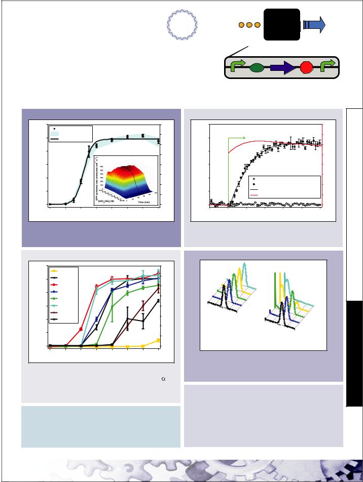
Static Performance*
) |
600 |
|
|
|
|
|
|
8 |
|
−1 |
|
Population Mean |
|
|
|
|
|
||
s |
|
|
|
|
|
|
|||
|
Colony Range |
|
|
|
|
7 |
|
||
−1 |
500 |
|
|
|
|
|
|||
cell |
Hill Equation |
|
|
|
|
|
|
||
|
|
|
|
|
|
|
|||
|
|
|
|
|
|
|
6 |
|
|
synthesis rate (molecules |
|
|
|
|
|
|
|
|
|
400 |
|
|
|
|
|
|
5 |
|
|
|
|
|
|
|
|
|
−1 |
||
|
|
|
|
|
|
|
|
||
300 |
|
|
|
|
|
|
4 |
PoPS cell |
|
200 |
|
|
|
|
|
|
3 |
||
|
|
|
|
|
|
|
|||
|
|
|
|
|
|
|
2 |
||
100 |
|
|
|
|
|
|
1 |
||
|
|
|
|
|
|
|
|||
GFP |
|
|
|
|
|
|
|
|
|
0 |
|
|
|
|
|
|
0 |
|
|
|
|
|
|
|
|
|
|
||
|
0E+00 |
1E−10 |
1E−09 |
1E−08 |
1E−07 |
1E−06 |
1E−05 |
1E−04 |
|
|
|
|
|
[3OC6HSL] (M) |
|
|
|
|
|
|
|
Pmax [3OC6HSL] |
n |
P |
: 6.6 PoPS cell-1 |
|
|
|
Pout |
= |
|
max |
|
|
|
||
|
|
|
|
|
||||
|
|
K: |
1.5E-09 M 3OC |
6 |
HSL |
|||
Kn + [3OC HSL]n |
||||||||
|
|
n: |
1.6 |
|
||||
|
|
6 |
|
|
|
|||
Input Compatibility*
) |
600 |
C4HSL |
|
|
|
|
|
8 |
|
−1 |
|
|
|
|
|
|
|
|
|
s |
|
C6HSL |
|
|
|
|
|
7 |
|
−1 |
500 |
|
|
|
|
|
|
||
cell |
|
3OC6HSL |
|
|
|
|
6 |
|
|
synthesis rate (molecules |
400 |
C7HSL |
|
|
|
|
|
5 |
|
|
C8HSL |
|
|
|
|
|
−1 |
||
|
|
|
|
|
|
|
|||
300 |
3OC8HSL |
|
|
|
|
4 |
PoPScell |
||
|
C10HSL |
|
|
|
|
|
3 |
||
200 |
C12HSL |
|
|
|
|
|
|||
|
|
|
|
|
|
||||
|
|
|
|
|
|
|
2 |
||
100 |
|
|
|
|
|
|
1 |
||
|
|
|
|
|
|
|
|||
GFP |
|
|
|
|
|
|
|
|
|
0 |
|
|
|
|
|
|
0 |
|
|
|
|
|
|
|
|
|
|
||
|
0E+00 |
1E−10 |
1E−09 |
1E−08 |
1E−07 |
1E−06 |
1E−05 |
1E−04 |
|
|
|
|
|
[AHL] (M) |
|
|
|
|
|
Part Compatibility (qualitative)
Chassis: |
MC4100, MG1655, and DH5 |
Plasmids: |
pSB3K3 and pSB1A2 |
Devices: |
E0240, E0430 and E0434 |
Transcriptional Output Demand (low/high input)
Nucleotides: 0 / 6xNt nucleotides cell-1 s-1
Polymerases: 0 / 1.5E-1xNt RNAP cell-1
(Nt = downstream transcript length)
Dynamic Performance*
) |
600 |
|
|
|
|
|
|
|
|
|
|
|
|
|
|
|
8 |
|
−1 |
|
|
|
|
|
|
|
|
|
|
|
|
|
|
|
|
|
|
s |
|
+ 3OC6HSL |
|
|
|
|
|
|
|
|
|
|
|
|
7 |
|
||
−1 |
500 |
|
|
|
|
|
|
|
|
|
|
|
|
|
||||
cell |
|
|
|
|
|
|
|
|
|
|
|
|
|
|
|
|
|
|
|
|
|
|
|
|
|
|
|
|
|
|
|
|
|
|
6 |
|
|
synthesis rate (molecules |
|
|
|
|
|
|
|
|
|
|
|
|
|
|
|
|
|
|
400 |
|
|
|
|
|
|
|
|
|
|
|
|
|
|
|
5 |
|
|
|
|
|
|
|
|
|
|
|
|
|
|
|
|
|
|
−1 |
||
|
|
|
|
|
|
|
|
|
|
|
|
|
|
|
|
|
||
300 |
|
|
|
|
|
|
|
|
|
|
|
|
|
|
|
4 |
PoPS cell |
|
200 |
|
|
|
|
|
|
GFP synthesis rate (Low Input) |
3 |
||||||||||
|
|
|
|
|
|
|
||||||||||||
|
|
|
|
|
|
|
|
|||||||||||
|
|
|
|
|
|
|
GFP synthesis rate (High Input) |
2 |
||||||||||
100 |
|
|
|
|
|
|
Polynomial Fit (High Input) |
|
|
|
||||||||
|
|
|
|
|
|
PoPS (High Input) |
|
|
|
|
1 |
|||||||
|
|
|
|
|
|
|
|
|
|
|
||||||||
GFP |
|
|
|
|
|
|
|
|
|
|
|
|
||||||
0 |
|
|
|
|
|
|
|
|
|
|
|
|
|
|
|
0 |
|
|
|
|
|
|
|
|
|
|
|
|
|
|
|
|
|
|
|
||
|
−10 |
0 |
10 |
|
|
|
|
|
20 |
30 |
|
40 |
|
|
50 |
|
|
|
|
|
|
|
|
|
Time (min) |
|
|
|
|
|
|
|
|||||
BBa_F2620 Response Time: |
|
|
<1 min |
|
||||||||||||||
BBa_T9002 Response Time: |
|
|
6±1 min |
|||||||||||||||
Inputs: 0 M (Low), 1E-07 M (High) 3OC6HSL |
||||||||||||||||||
Reliability** |
|
|
|
|
|
|
|
|
|
|
|
|
|
|
|
|
||
|
|
|
|
|
|
|
92 |
|
|
|
|
|
|
|
|
|
|
|
|
|
|
|
|
74 |
|
ngs |
|
|
|
|
|
|
|
|
|
||
|
|
|
56 |
|
ubli |
|
|
|
|
|
|
|
|
|
||||
|
|
|
38 |
|
|
|
|
|
|
|
92 |
|
|
|||||
|
1E0 |
1E1 |
Do |
|
|
|
|
|
|
|
|
|
||||||
|
GFP |
20 |
|
|
|
|
|
|
|
|
|
|
|
|||||
|
1E2 |
|
|
|
|
|
|
|
|
74 |
|
ings |
|
|
||||
|
|
1E3 |
1E4 |
|
|
|
|
|
|
|
|
|
|
|
|
|
|
|
|
|
(arbitrary |
|
|
|
|
|
|
|
|
|
|
|
56 |
|
|
|
|
|
Low Input units) |
|
|
GF |
1E0 |
1E1 |
|
38 |
Doubl |
|
|
|
||||||
|
(0 M 3OC6HSL) |
|
|
|
|
1E2 1E3 |
20 |
|
|
|
||||||||
|
|
|
|
|
P |
|
|
|
|
|||||||||
|
|
|
|
|
|
|
|
|
|
(arbitrary |
1E4 |
|
|
|
|
|
||
|
|
|
|
|
|
|
|
|
|
units) |
|
|
|
|
|
|||
|
|
|
|
|
|
|
|
|
High Input |
|
|
|
|
|
||||
|
|
|
|
|
|
(1E -7 M 3OC6HSL) |
|
|
|
|
|
|
||||||
Genetic: >92/>56 culture doublings Performance: >92/>56 culture doublings
(low/high input during propagation)
Conditions (abridged)
Output: |
PoPS measured via BBa_E0240 |
Culture: |
Supplemented M9, 37ºC |
Plasmid: |
pSB3K3 |
Chassis: |
MG1655 |
*Equipment: |
PE Victor3 multi-well fluorimeter |
**Equipment: |
BD FACScan cytometer |
Signaling Devices http://parts.mit.edu/registry/index.php/Part:BBa_F2620
Authors: |
Barry Canton |
Registry of Standard Biological Parts |
License: Public |
|
Ania Labno |
||
|
making life better, one part at a time |
||
Updated: |
March 2008 |
|
BioBrick Promoter Measurement Kit
Assembly Instructions
pSB1A2-E0240 pSB3K3-P1010
E X |
E0240 |
S P |
E X |
ccdb toxin |
S P |
AmpR |
|
pUC |
|
KanR |
p15A |
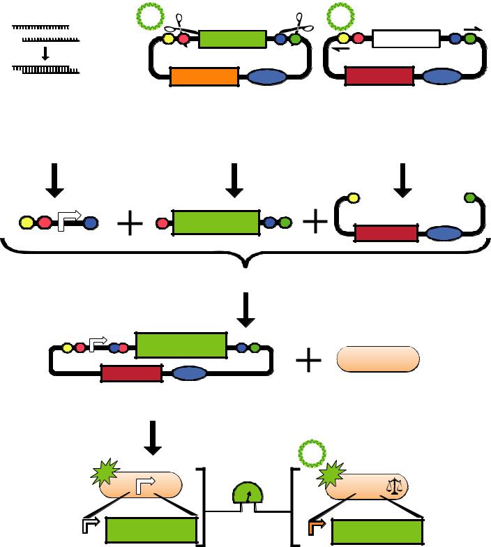
STEP1: Prepare the test promoter φ by annealing synthesized oligos leaving EcoRI and SpeI sticky ends.
E X φ S
STEP2: Prepare the GFP reporter device (BBa_E0240) by miniprep of pSB1A2-E0240 followed by restriction digest with XbaI and PstI.
X |
E0240 |
S P |
STEP3: Prepare backbone plasmid (pSB3K3) by preperative PCR of pSB3K3-P1010 using primers BBa_G1000 and BBa_G1001 followed by restriction digest with EcoRI and PstI.
E P
KanR p15A
STEP4: Combine the test promoter φ, GFP reporter device, and backbone plasmid in a 3-way ligation to build the promoter test construct.
E X |
φ |
Mixed |
E0240 |
S P |
|
|
|
TOP10 |
|
|
|
|
|
KanR 3
STEP5: Transform the promoter test construct into TOP10 cells. Select for transformants on Kanamycin plates.
|
|
|
pSB3K3-I20260 |
|
|
SPU |
TOP10 |
|
φ |
|
|
|
|
I20260 |
|
φ |
E0240 |
|
E0240 |
|
|
|
J23101 |
STEP6: Measure the activity of the test promoter φ relative to the activity of the reference standard promoter (BBa_J23101). Report promoter φ activity in relative units of Standard Promoter Units (SPUs).

BioBrick Promoter Measurement Kit
Measurement Instructions
STEP1: Streak 3 plates
A:TOP10
B:BBa_I20260
C: Your promoter!
STEP 2: Pick 3 colonies from each plate to start overnight cultures in Supplemented M9 Media at 37 C (9 tubes)
TOP10
BBa_I20260 |
37C |
16 hours |
Your Promoter |
|
|
STEP 3: Dilute 1/100 into fresh, pre-warmed media incubate at 37C (9 tubes)
STEP 4: After 3 hours measure GFP and OD
37C
STEP 5: After another half hour measure GFP and OD again
3 hours |
GFP OD |
1/2 hour |
GFP OD |
|
|
STEP 6: Input your data into the SPU Calculator and report your results at: http://partsregistry.org/measurement
Practice Promoter Set
Weak (J23150), medium (J23151), and strong (J23102) promoters have already been assembled into promoter test constructs and are ready to measure! Transform the 3 test constructs into TOP10 and measure using the
protocol above. Report your results at: http://partsregistry.org/measurement
SPU
1.2 |
|
|
1.0 |
0.96 |
|
0.8 |
||
|
||
0.6 |
0.55 |
|
0.4 |
||
|
0.20.26
0.0 

J23150 J23151 J23102

p e r s p e c t i v e
© 2008 Nature Publishing Group http://www.nature.com/naturebiotechnology
Refinement and standardization of synthetic biological parts and devices
Barry Canton1,4 Anna Labno2–4 & Drew Endy1
The ability to quickly and reliably engineer many-component systems from libraries of standard interchangeable parts is one hallmark of modern technologies. Whether the apparent complexity of living systems will permit biological engineers to develop similar capabilities is a pressing research question. We propose to adapt existing frameworks for describing engineered
devices to biological objects in order to (i) direct the refinement and use of biological ‘parts’ and ‘devices’, (ii) support research on enabling reliable composition of standard biological parts and (iii) facilitate the development of abstraction hierarchies that simplify biological engineering. We use the resulting framework to describe one engineered biological device, a genetically encoded cell-cell communication receiver named BBa_F2620. The description of the receiver is summarized
via a ‘datasheet’ similar to those widely used in engineering. The process of refinement and characterization leading to the BBa_F2620 datasheet may serve as a starting template for producing many standardized genetically encoded objects.
Although many biotechnology applications have been developed1, the scope and scale of imaginable applications exceed current abilities to  implement them2,3. In part this is because the design and construction
  of engineered biological systems remains an ad hoc process for which costs, times to completion and probabilities of success are difficult to estimate accurately4. Ideally, biological engineers might develop a design and construction framework that makes routine the incorporation of basic biological functions into many-component integrated genetic systems that behave as expected. Mature engineering disciplines have developed similar frameworks by using the concept of abstraction to define sets of standardized, functional objects that can be used in combination, together with composition rules5 that specify how such
objects should be assembled.
Composition rules and abstraction are just beginning to be applied to the engineering of biology. For example, BioBrick standard biological parts (http://partsregistry.org/) are an early collection of genetically encoded functions that conform to simple rules supporting physical composition6 and guidelines for functional composition7 (Box 1 and Figs. 1 and 2). As a second example, in support
1Department of Biological Engineering and 2Departments of Biology and Physics, Massachusetts Institute of Technology, 77 Massachusetts Ave., 68580, Cambridge, Massachusetts 02139, USA. 3Present address: Biophysics Graduate Group, MC 3200, University of California, Berkeley, California 94720, USA. 4These authors contributed equally to this work. Correspondence should be addressed to D.E. (endy@mit.edu).
Published online 8 July 2008; doi:10.1038/nbt1413
of functional composition, researchers recently developed a set of prokaryotic promoters that have reduced contextual dependencies in reported promoter activities8. We next need to produce quantitative descriptions9 that facilitate the reuse of first-generation parts and devices and enable the development of specifications prescribing the design of next generation parts and devices that are engineered to better support composition and abstraction.
Lessons from engineering experiences
Quantitative descriptions of devices in the form of standardized, comprehensive datasheets are widely used in the electrical10, mechanical, structural and other engineering disciplines (for examples see http:// www.mcmaster.com/). A datasheet is intended to allow an engineer to quickly determine whether the behavior of a device will meet the requirements of a system in which the device might be used. Such a determination is based on a set of standard characteristics of device behavior, which are the product of engineering theory and experience10–13. The characteristics typically reported on datasheets are common across a wide range of device types, such as sensors, logic elements and actuators: first, a definition of the function and interfaces of the device (inputs and outputs); second, the operating context of the device; third, measured characteristics describing the quantitative behavior of the device.
A crucial measured characteristic is the transfer function, which details the static relationship between device input(s) and output(s) and allows prediction of the equilibrium behavior of composed devices. The dynamic behavior of the device is often reported so that the response time of the device can be compared to the expected timing of the overall system. It is important to report compatibility of device function with other devices or different operating conditions whenever the context in which the device operates is expected to vary. The reliability, or expected time to failure of a device, is also relevant whenever correct device performance over longer timescales is required. Finally, a description of the power and material resources consumed by a device informs the choice of a suitable power supply and resource pools for the system.
We propose to adopt a similar framework for describing engineered biological devices. Despite the differences in materials and mechanisms, biological devices may often be defined with functions that are identical to the functions of electrical, mechanical and other types of existing engineered devices. Biological equivalents of sensors14–16, logic gates17–19 and actuators20 have all been demonstrated. Consequently, many of the characteristics found on existing device datasheets might also be useful for biological device datasheets. For example, the transfer function and dynamic behavior characteristics are directly applicable to any biological device with well-defined inputs and outputs. Compatibility of a biological device with genetic backgrounds, growth conditions or
nature biotechnology volume 26 number 7 july 2008 |
787 |