

Design of an active acoustic sensor system for an autonomous underwater vehicle
.pdfHardware Design
The hardware design of the active sonar system is crucial to the AUV successfully determining its distance from an obstacle. It is imperative the system be able to communicate this information accurately to the CPU so that informed decisions can be made while the AUV navigates the surrounding environment.
Although imaging sonar systems are preferable, due to financial constraint, a discrete sonar system is employed. Consequently, the active sonar system is comprised of four individual echo sounding units. Three facing the port, starboard, and bow sides for detection of lateral obstacles and one facing down to provide depth measurement.
4.1 Commercially Available Echo Sounders
Although not of high quality, commercially available depth sounders are relatively inexpensive, and are adequate for simple echo sounding tasks. It was necessary, however, to determine the suitability of using depth sounders as proximity sensors on the AUV. One such depth sounder was tested, and the results are described in the following sections.
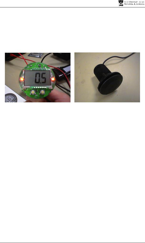
4.1.1 The Navman Depth2100 Echo Sounder
Initially, the Navman echo sounder was purchased to provide depth readings for the AUV. The idea came from the fact the boats could achieve depth readings from commercially available echo sounders with reasonable accuracy at a far lesser cost than purchasing a digital altimeter.
From this idea of depth measurements stemmed the idea that the echo sounder did not necessarily only have to measure depth, but could also measure proximity of objects and
27
Design of an Active Acoustic Sensor System
surfaces in the lateral directions. Thus, although the echo sounders were initially only intended for depth measurements, it was determined that an array of these sensors could function as a complete acoustic sensor system.
However, an acoustic sensor system based on echo sounders requires a device of far superior performance than the Navman Depth2100, which was consequently no longer suitable for the project.
Figure 4.1a) & b): the Navman echo sounder circuit board and transducer
4.1.2 Shortcomings of the Navman Depth 2100 Echo Sounder
There are several key problems with the Navman echo sounder that make the device a poor choice when it comes to use on the AUV. These problems are:
•An inaccurate resolution of 10cm
•A very slow data rate of 1 Hz
•A serial data line
•Lack of programmability
Having a resolution of 10cm means that the AUV will not be able to accurately maintain specific distances from objects or maintain a specified depth. Since the echo sounder will be used mainly for navigation and collision detection, the resolution needs to be better than 5cm, as stated in chapter 3.
The data rate of 1 Hz is also very slow. This means that the AUV will not be able to adjust quickly enough to any immediate changes to the environment, and must rely on the fact that changes are gradual and the environment is predictable. However, the environment is never completely predictable, thus the data rate of the echo sounder needs to be much faster to accommodate for uncertainties within the environment.
28

Chapter 4 Hardware Design
The echo sounder is not programmable which means that the echo sounder parameters are not controllable. The only aspect of the echo sounder that is controllable is turning the echo sounder on or off. Thus, if data is required, the echo sounder is turned on, if the data is not required, the sounder is turned off. This means that the sounder is not very practical for the AUV.
The serial data line results in the following problems:
•Insufficient serial ports available on the Eyebot
•The need for development of a protocol to distinguish between each of the individual echo sounders, which are operated simultaneously.
•Unacceptable delays in sound detection due to potentially longer than four second read cycles.
Taking these factors into consideration, the Navman echo sounder is not functionally adequate for use with the AUV. Furthermore, only by significantly changing the hardware, and possibly the software, can the Navman echo sounder perform the tasks required.
4.2 Need for a New Design
A better option is to design a new echo sounder circuit board with the functionality required to achieve the goals of the AUV. Since cost is such a limiting factor on the design of the acoustic sensor system, there must be a significant amount of bias towards designing a cheaper system. Also, as the AUV is completely operated on batteries, there must be a consideration towards the power consumption of the system, but not at the expense of cost benefits.
4.2.1 Number of Transducers
The number of transducers is an important decision concerning the design of an acoustic system. The options are a one or two transducer echo sounder.
The main advantage of a two transducer system is that the resonant frequency of the transmitter transducer can be matched to the anti-resonant frequency of the receiver, as discussed in chapter 2. This will enable maximum power emission efficiency for the transmitter and maximum power reception efficiency at the receiver. At other frequencies, the transducer has some reactance, meaning power is not transferred as efficiently. A single
29
Design of an Active Acoustic Sensor System
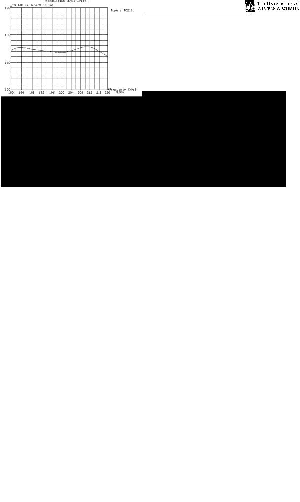
transducer attempts to minimise the gap between the two frequencies, but as can be seen in figure 4.2, they do not exactly match. The plots demonstrate the receiving anti-resonant frequency as a peak in figure 4.2a), and the transmitting resonant frequency as a local minimum in figure 4.2b). The optimal frequency for a single transducer will be close to both the anti-resonant and resonant frequency.
Figures 4.2 a) & b): Receiver and transmitter sensitivities of a single transducer [19]
The problem is that the two transducer system is more expensive due to the need to purchase two transducers. As there is a greater priority placed on cost than there is on power conversion efficiency, the single transducer design is selected. The transducer will still resonate, but not to the same extent as a two transducer system.
4.2.2 Choice of Transducer
There are many types of transducers available on the market, varying in both price and quality. Obviously, the more expensive the transducer, the better the quality is. Thus, the choice of transducer must hinge heavily on the type of application the transducer will be used for. It must be investigated whether a less expensive transducer can fulfil the requirements for the acoustic sonar system.
The type of application that the echo sounder is to be used for is basic echo sounding. This application requires the use of a transducer that can effectively transmit and detect an acoustic ping in water. Since the range for the echo sounder will be in the order of 10 metres, the sensitivity of the transducer is not a very significant concern.
Another factor that is used to determine the type of transducer is the power consumption of the transducer and the echo sounder as a whole, as stated earlier in this section. This can be accomplished by choosing a transducer that outputs less power. However, the power consumption is also closely linked to the range of the echo sounder. If low power
30

Chapter 4 Hardware Design
consumption is required, a smaller power acoustic ping can be transmitted, meaning that the range of the echo sounder is reduced.
More expensive transducers only have slightly better physical characteristics than the much cheaper transducers found on fish finders and boat depth sounders. The difference between the two comes down to the fact that the more expensive transducer is developed closer to specification than the cheaper transducer, and thus is more reliable and better specified.
However, for the purposes of the project, the cheaper Navman transducer is capable of achieving the tasks at a lesser expense than the Reson TC 2111 and consumes less power [19], [20]. Thus, since a greater weighting has been placed on producing the circuit at the least cost, the choice of the inexpensive transducer over the more specified transducer has been made.
4.2.3 Choosing a Design for a New Circuit
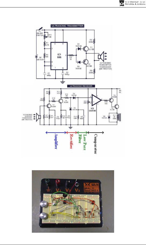
Much time was spent on investigating ways in which to approach the task of designing a new echo sounder circuit that could fulfil the requirements set in Chapter 3. There is little information on the design of underwater echo sounder circuits that is readily available both on the Internet and in literature. The initial time spent researching methods focussed mainly on adapting ultrasonic switches or AM transmitters. Figure 4.3 shows an example of an ultrasonic switch that was tested for suitability [21]. Figure 4.4 shows the circuit layout on a prototyping board.
The transmitter for this design was flawed, with respect to underwater echo sounding, as there is less than 9V supplied to the transducer, with this voltage not being stepped up before transmission. This meant that the system could only work within a range of less than 1m due to a lack of signal intensity, which is not sufficient when the system is converted to an underwater system.
The receiver was a very basic circuit of only a few parts. The first was a two transistor amplifier. The second was an envelope detector consisting of a rectifier followed by a low pass RC filter. The comparator at the end just sets the threshold for the logic. The simplicity of this design meant that it was very limited in its ability to detect signals.
Other problems with these types of design are that they cannot be easily ported to a single transducer system and that there are many components that will reduce the SNR of the
31
Design of an Active Acoustic Sensor System
system, decreasing the chances of detecting an echo. A circuit that caters for a single transducer and has fewer components on the circuit board is needed for this project.
Figure 4.3: Design for an ultrasonic switch [21]
Figure 4.4: Circuit layout of an ultrasonic switch
32

Chapter 4 Hardware Design
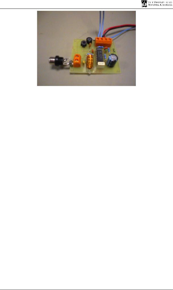
4.2.4 Design of a Circuit Prototype
A design that utilised a National Semiconductor LM1812 ultrasonic transceiver chip was used for development of the echo sounder circuit. Though the line of LM1812 chips is no longer in production, they are still available from vendors internationally. This design was determined to be the best to design a prototype with.
Figure 4.5: Circuit diagram of the echo sounder circuit design [14]
Obtaining a copy of the datasheet from National Semiconductors [14], it was found that the chip could be used in a circuit (Figure 4.5), similar to one designed in the datasheet, which could fulfil the task of underwater echo sounding.
Figure 4.6: Echo sounder communication lines with a microcontroller
Figure 4.6 demonstrates how the microcontroller communicates with the echo sounder circuit. Basically, the circuit is a device that links to a microcontroller and only has provisions for sending and receiving a 200 kHz frequency from the transducer. The pulse, which is modulated to the 200 kHz carrier frequency, must be supplied by the microcontroller. Also, any timing must be accomplished by the microcontroller.
33
Design of an Active Acoustic Sensor System
Figure 4.7: Circuit board of prototype
4.2.5 Advantage of the Prototype Design
It may seem like the whole system will be limited in ability due to the circuit’s simplicity, but it is in fact quite beneficial. Since most of the echo processing is completed by the microcontroller, the system becomes quite flexible, allowing it to closely match the design requirements for the project.
Because the timing is handled by the microcontroller, the echo sounding system is no longer limited by a set program, preset in a microcontroller of the echo sounder, like the Navman echo sounder. In the Navman echo sounder, the echo sounding program, including the transmission, reception and timing of the ultrasonic pulse was already preset in the echo sounder’s microcontroller. The problem with this was that it is virtually impossible to reprogram the microcontroller with more efficient code, as the code set for the microcontroller is unknown. Thus the only output possible from this echo sounder is the serial data in the NMEA 0183 protocol format, which only provides serial data at a rate of 1Hz. Thus the key parameters of range, resolution and data rate can be adjusted on the new circuit prototype.
Since the input and output of the echo sounder are only logic and not in serial form, they can be easily interfaced to any microcontroller’s digital output and input (IO) with no need to provide a protocol for transferring data. Also, with the basic input and output of the circuit, it is not difficult to interface more than one device to the digital IO, as microcontrollers usually have an abundance of IO ports. Thus, interfacing with the Eyebot is much simpler.
34

The Eyebot Interface
The interfacing of the echo sounder to the Eyebot is an important design step because without proper interfacing, both in hardware and software, the sensor will not be able to communicate information to the Eyebot, rendering the sensor useless. Design choices such as the type of interface, method of connection and implementation of software are discussed in this chapter.
5.1 Choosing the Interface
The echo sounder circuit is very basic in its technique for transmitting and receiving a signal. The circuit provides a modulated signal that needs to be switched on and off for an acoustic pulse to be transmitted. The return signal is then detected by the circuit and represented by a low on the circuit’s logic output. There is no provision for the processing of distance measurements by the echo sounder. All this must be completed on a different circuit or microcontroller. Before the echo sounding circuit prototype can be used with the Eyebot, an interface with the Eyebot needs to be established.
5.1.1 Eyebot versus Onboard Transmission and Detection
There are two ways to establish a connection between the echo sounder and the Eyebot, each with there own benefits and disadvantages, which need to be assessed so that the most effective solution can be found.
The method of performing the signal processing on the Eyebot’s Motorola 68332 microcontroller is preferred, as opposed to performing it on a separate microcontroller. The reasons for this are:
35

Design of an Active Acoustic Sensor System
•There is no need to set up a transfer protocol between the Eyebot’s microcontroller and the other microcontrollers. If the data was processed separate from the Eyebot microcontroller, then the data would need to be transferred to the Eyebot. The only solution is to send data via a serial protocol. This would consume much time, and it would be difficult to multiplex multiple sounders to the one Eyebot. It is more efficient to process the data on the Eyebot.
•There is no need to purchase other microcontrollers and learn the code set for them.
•The Motorola chip has a theoretical resolution capability of up to 238.4ns which is more than sufficient for echo sounding.
The only disadvantage of this solution is that the Eyebot will not be able to process other data during the detection and processing of the data from the echo sounder, which may have an effect on the timing of other processes. However, as long as this is taken into consideration whilst designing the interface, then the problem can be minimised or even eliminated.
Thus the choice is clear that the Motorola MC68332 CPU (Central Processing Unit) on the Eyebot will be used for the signal detection of the echo sounder. The Motorola microcontroller has a number of features allowing for flexibility in the development of an interface between the Eyebot and the echo sounder.
5.1.2 Choosing a Direct Connection to the Eyebot
The problem lies in how to utilise the functions available on the CPU to effectively create an interface. The solution to the problem requires choosing the most effective method of providing the input to the echo sounder and of receiving the output returned from the echo sounder.
The echo sounder has two pins, which connect to a microcontroller. One pin is the key input where the CPU sends the required pulse signal that will be modulated with the 200 kHz carrier frequency and transmitted through the transducer. The second pin that connects to the CPU is the logic output of the echo sounder. This output will be pulled low only when there is a 200 kHz signal received on the transducer line. This may occur several times for every pulse that is transmitted because the echoes from different surfaces will be just delayed versions of the signal. Therefore, the Eyebot interface is basically a pulse signal through the key input pin, followed by the delayed reception of a number of pulse echoes.
36