

Design of an active acoustic sensor system for an autonomous underwater vehicle
.pdfChapter 2 Underwater Sound Transmission and Navigation
Figure 2.1: Multipath environments cause ambiguity at the receivers
They investigate the effect that reverberations, or unwanted echoes, in the multipath environment have on the ability of a system to locate a source. This is an important result as the AUV will always be in these environments. They are able to obtain the variance of localisation error and also demonstrate that in regions where the time delays of the multipath signals matched the direct signal, large source localisation errors occur.
2.2 Active Acoustic Sensor Systems
Passive sonar does not allow an AUV to avoid obstacles. Therefore, in order to navigate effectively around obstacles underwater, a well designed active sonar system needs to be designed. This involves the proper design of a hardware system and a software system to complement it. The hardware component must be designed to suit the nature of the navigation that the AUV is supposed to complete. More complex navigation on larger AUVs require the use of more sophisticated sonar systems than AUVs that only need to navigate simple obstacle courses, but these come at a much greater cost. The software and navigation algorithms work in unison with the hardware to allow for reliable navigation to be executed by the AUV.
Many different approaches have been suggested as to how to implement a sensory system on an AUV. A common approach is to create some form of imaging sonar. Williams et al. [8] describe a system with ready-made imaging sonar that provides 360 degrees of sonar vision for the AUV. This device can be directly linked to a navigational computer for analysis. The
7
Design of an Active Acoustic Sensor System
imaging sonar provides a full graphical display of the sonar returns that the device collects. By using this data, the AUV has a continuous 360 degree view of its environment to allow it to easily determine the locality of obstacles and itself within unstructured terrain.
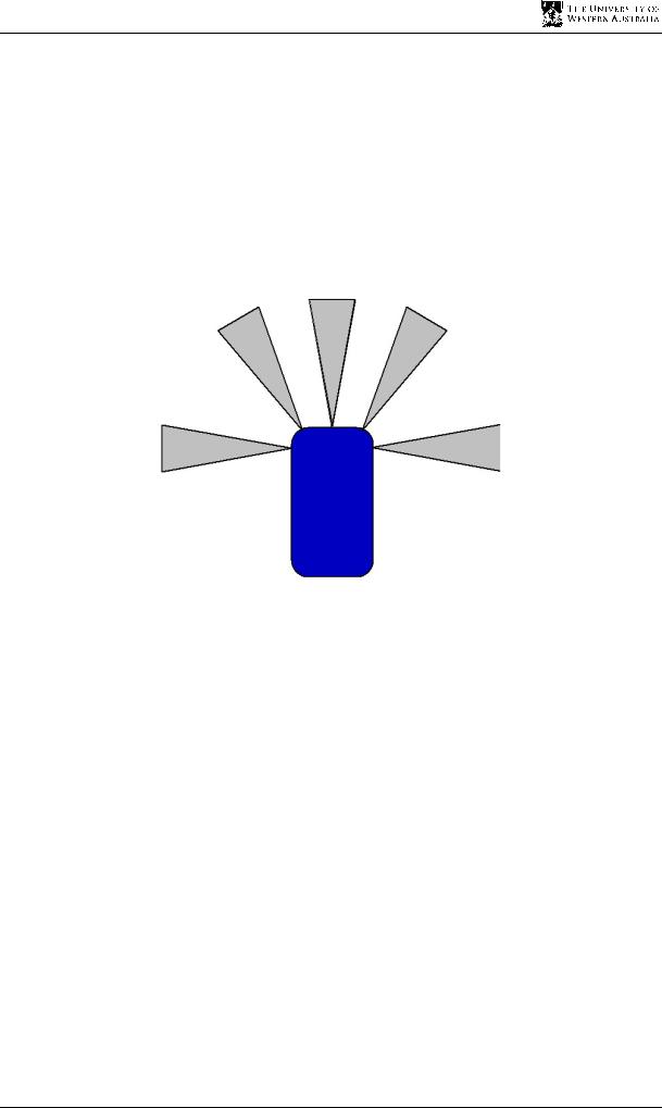
In contrast, Ip and Rad [9] explore the use of discrete sonar sensors that are mounted at specific intervals around the robot so that it can sense the proximity of obstacles that are around it. This design is different from the one that is implemented by S. B. Williams et al. (2000) in that the AUV does not have the full view of the surrounding environment, only discrete distances at specific intervals around the robot as in Figure 2.2.
Figure 2.2: Circular array demonstrating the discrete nature of data
This design also has not been implemented on an AUV, but carries the same principle that could be used with the AUV.
Yet another different approach is discussed by Ruiz et al [10]. The entire system for their AUV consists of a Doppler velocity log, a tri-axial compass and side scan sonar. Side scan sonar is similar to the 360 degree imaging sonar except that it can only see in a narrow field of vision.
2.3 Fundamentals of Sonar Sensing
Sound transmission is a key part of underwater navigation as other forms of sensing, such as light, do not have the range capabilities that sound has underwater. In order to successfully use sonar to determine range of objects, one must understand how echo sounding works and what may affect the detection of a sonar signal.
8
Chapter 2 Underwater Sound Transmission and Navigation
2.3.1 Echo Sounding Principles
The echo sounder works on a very simple principle. The operation of the transmitter and receiver is similar to a basic AM transmitter and receiver.
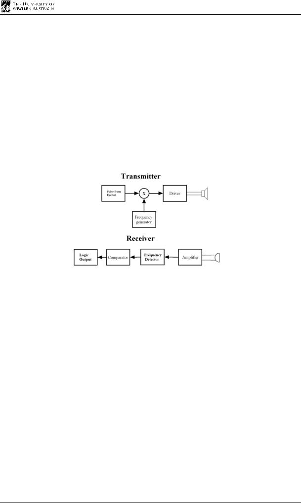
A microcontroller, such as the Eyebot’s Motorola 68332 microcontroller, will send the sensor a pulse signal. The sensor then uses this pulse signal to switch a carrier signal of particular frequency on and off, similar to an AM transmitter switching between a maximum and zero amplitude signal. This modulated pulse signal is then driven using a transformer to increase the amplitude of the signal enough for the signal to travel a significant distance. The transducer then converts the signal from electrical to acoustic vibrational energy through its piezo-electric material. Figure 2.3 shows the operation of the echo sounder.
Figure 2.3: Echo sounder operation flow chart
On receiving the signal, the transducer converts the acoustic signal back to an electrical signal and then the signal is amplified to increase the signal strength. It is then passed through a frequency detector to determine if the right frequency has been received. On confirmation of a correct signal, the logic output to the microcontroller is then driven low to indicate a successful reception of the pulse signal.
2.3.2 The Sonar Equation
For active sonar where reverberations, or echoes, have a strong presence, the signal strength needs to satisfy the following equation, in order for the acoustic system to be able to identify the signal transmitted [11]:
SL - 2TL +TS - RL + DI ≥DT |
(2.1) |
•SL is the sound level of the transmitter, or intensity at the transmitter
9

Design of an Active Acoustic Sensor System
•TL is the loss of sound level during transmission of the signal in one direction.
•TS is the target strength and is dependent on the reflectivity of the given surface.
•RL is the level of reverberation, or echoes, encountered at the receiver.
•DI is the directivity index of the transducer, with a higher DI indicating more sound is transmitted in the desired direction.
•DT is the detection threshold and is defined as the signal level required allowing detection of the signal for 50 percent of the time.
All components are in decibels.
The equation is very similar for the passive sonar case, except the target strength is no longer applicable because the signal is not reflected of a target surface, and the transmission loss is only in one direction meaning that the multiplier for the TL is removed. The equation is as follows:
SL -TL - RL + DI ≥DT |
(2.2) |
2.4 Transmission Losses in Acoustic Systems
For sound to travel in a medium, the acoustic media must be compressible. A local disturbance cannot instantaneously travel from one point to another, but must take a finite amount of time to be transmitted, depending on the compressibility and the density of the medium [12].
In most cases in any form of media, the intensity of sound waves continuously decreases over the distance that they propagate. This can be usually accounted for by geometrical spreading of a wave as well as the absorption and scattering of energy from the wave by the medium involved. Then there are the frequency dependent components of loss and also reverberations that may cause the degradation of the signal.
2.4.1 Transmission Intensity Losses of Acoustic Systems
The intensity at two radially different points in space would have the intensities I1 and I2 . For spherical waves, the surface area is related to the square of the radius of the wave front, thus:
10

Chapter 2 Underwater Sound Transmission and Navigation
|
|
|
r1 |
2 |
|
|
I2 |
= |
|
|
(2.3) |
||
|
||||||
I1 r |
|
|||||
|
|
|
2 |
|
|
|
However, usually the source provides some directionality for its sound waves and the intensity rule cannot apply. More often, the equation is usually modified to:
|
|
|
r1 |
n |
(2.4) |
I2 |
= |
|
|
||
I1 r |
|
|
|||
|
|
|
2 |
|
|
The n in the equation is dependent on the directionality of the wave emitted from the source and is non-integral and less than two.
2.4.2 Scattering and Absorption Losses of Acoustic Systems
Scattering and absorption of the medium provide another common loss of intensity of the sound wave. The percentage loss over a particular distance is constant and can thus be written as an exponential term with an absorption coefficient, a. This gives rise to the equation:
|
|
n |
|
|
|
|
I2 |
|
r1 |
|
exp[2a(r2 |
− r1 )] |
(2.5) |
|
||||||
= I1 r |
|
|||||
|
2 |
|
|
|
|
|
By taking the logarithms of both sides of the equation, and then rearranging the equation, the propagation loss, N, or the difference of intensity can be termed as:
|
|
|
|
(2.6) |
|
r1 |
|
+α(r2 |
− r1 )+ H dB |
||
N =10n log10 |
|
|
|
||
r |
|
||||
2 |
|
|
|
|
|
The H term accounts for the differences between the theoretical losses and that which are observed, due to diffraction, reflection and refraction.
11

Design of an Active Acoustic Sensor System
2.4.3 Frequency Dependent Losses in Acoustic Media
Knowledge of the frequency dependent losses is important as it assists in determining what frequency is ideal for echo sounding.
The losses are associated with dissipation of heat due to frictional forms of energy. There are generally two losses of this form that are dominant in sound propagation; these are bulk viscosity and absorption due to relaxation [13]. It is usually the bulk viscosity that has the greatest effect on the attenuation of sound waves and is given by the following equation [2]:
α = |
2νω2 |
(2.7) |
v 3c3
In the equation, υ is the kinematic viscosity and ω is the angular frequency of the sound wave. This loss has a square dependence on frequency.
The second loss of excess absorption due to relaxation can be explained by the absorption and retransmission of energy from the medium. The time it takes for a particle to return to a relaxed state after it has absorbed energy from a sound wave is called the relaxation time, τ. If the energy is returned to the sound wave in phase, then the energy is added constructively. However, if the energy is returned to the sound wave out of phase, then it causes destructive interference. If the period of the wave is comparable to the relaxation time, then high attenuation occurs. The equation for this phenomenon is given by [12]:
α = 2αm |
f 2 fr |
(2.8) |
||
f 2 |
+ fr2 |
|||
|
|
|||
The αm term is the maximum attenuation coefficient at the relaxation frequency, 1/2πτ, and f is the frequency of the sound wave.
It can be seen from the above losses, that the any acoustic system is limited in range. The frequency of the sound wave propagating through a medium has a significant effect on the attenuation of the sound wave in the medium and thus on the effective range of the underwater acoustic system.
12

Chapter 2 Underwater Sound Transmission and Navigation
2.4.4 Reverberation Considerations for Acoustic Systems
Acoustic signals, especially in an environment that is relatively enclosed, such as a swimming pool, are backscattered off the many surfaces, meaning that the signal obtained by the receiver will contain components from many different ray paths, masking the direct path signal. These components are called reverberations. There is an upper limit to the source level that can be transmitted. This is due to the fact that higher source levels represent higher reverberation levels. This limit will be where the increase in signal to noise ratio (SNR) from the source level will be non-beneficial for the receiver as it is countered by the decrease in SNR from reverberation level, using equation 2.1. Thus the echo sounder must be designed to have just enough signal level to transmit over a desired range. Any more signal level will contribute unnecessarily to reverberation.
2.5 Characteristics of Acoustic Transducers
An acoustic transducer is a physical device that converts electrical energy to vibrational energy and vibrational energy to electrical energy. This section discusses the characteristics of an acoustic transducer. This includes the resonant frequency of an acoustic transducer and the directivity of a transducer.
2.5.1 The Resonant Frequency of an Acoustic Transducer
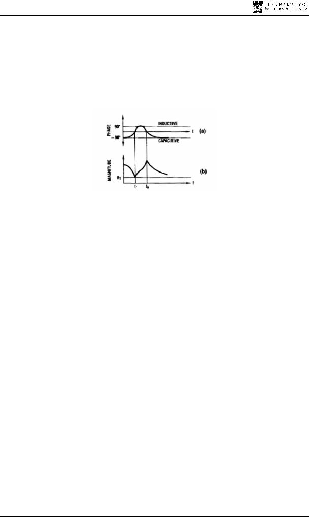
All materials have a resonant frequency, including the membrane of an acoustic transducer. This property of the material can be used to great advantage in the transmission and reception of an underwater acoustic signal. Resonance is an increase in the oscillatory energy absorbed by a material when the frequency of the oscillations matches the material's natural frequency of vibration. This property is very useful because it means that by sending the right frequency signal through the transducer, a higher percentage of power can be converted efficiently into the transmission of the signal. The resonance of the transducer also has another valuable property. Since the transducer can convert electrical signals to vibrational signals and vice versa, the same effect can occur when the transducer is receiving a signal. This is advantageous because the transducer material, therefore, naturally filters out noise from other frequencies, resulting in a better signal to noise ratio when the signal is received. Transducer materials can be made with the precise physical properties in order for it to resonate at a desired frequency. Figure 2.4 shows that a transducer has a resonant and anti-resonant
13
Design of an Active Acoustic Sensor System
frequency, shown as the minimum and maximum in the magnitude plot, respectively. A transmitter should transmit at the resonant frequency and the receiver should receive at the anti-resonant frequency. In a dual transducer echo sounder system, the transmitter transducer’s resonant frequency is tuned to the receiver’s anti-resonant frequency. In a single transducer system, the two frequencies are made as close as possible, but the system will be transmitting and receiving at a frequency that is not optimal, but between the two frequencies.
Figure 2.4: The resonant and anti-resonant frequency of a transducer [14]
The resonant and anti-resonant frequencies used for many boat depth sounders lie close 200 kHz. The resonant frequency of air transducers, such as the ones used in Polaroid’s sonar ranging system operate at a resonant frequency of 40 kHz.
2.5.2 Directivity of Circular Transducers
The directivity of the transducer is an important characteristic of an acoustic system. It is basically how directional the signal is transmitted. A transducer with high directivity will transmit more power in a particular direction than one with a lower directivity. By understanding the geometry and nature of the transducer, the directivity of the transducer can be found.
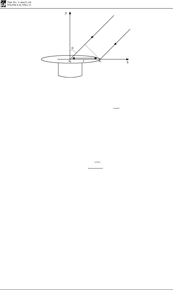
Firstly assume that the transducer is used for receiving a cosine wave that is sent from a source that is far away, such that the distance between the source and the transducer is very large in comparison to the length of the transducer. This allows the incoming waves to be considered parallel to each other as in Figure 2.5.
14
Chapter 2 Underwater Sound Transmission and Navigation
Figure 2.5: Sound waves being received by a transducer
The wave that is received at the centre of the transducer is cos(ωt). At a point that is r away
from the centre, the wave received is cos(ωt − kr), where k is 2λπ sinθ and λ is the wavelength
in the medium. The sensitivity is not uniform overall the surface, since the circular surface is wider in the middle than on the sides.
This directivity function for a circular transducer is derived to be a first order Bessel function of the first kind [12] as given below:
J1 Kl
D(K )= 2 2 (2.9)
Kl
2
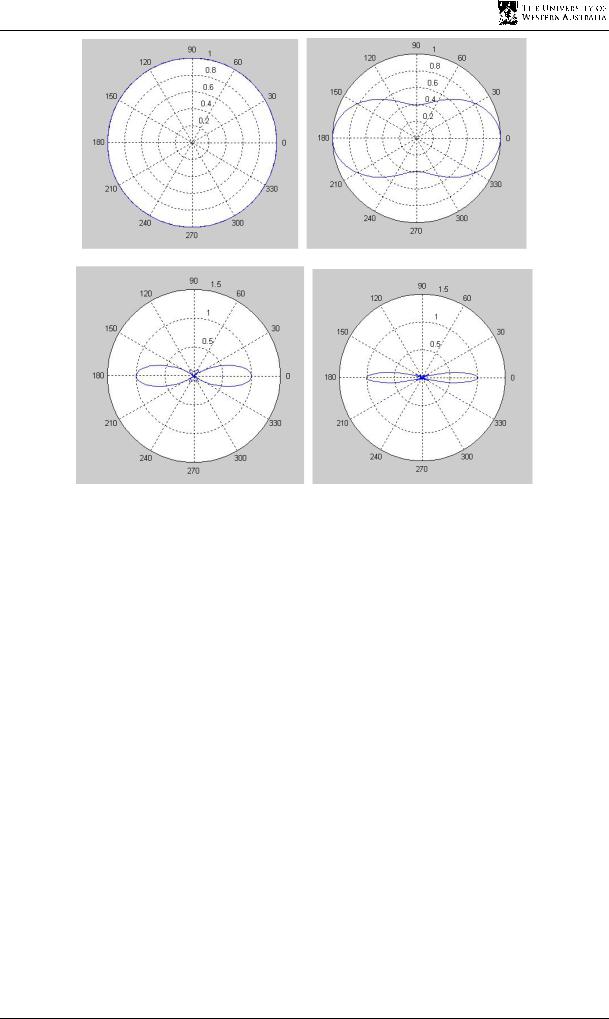
Polar plots from Matlab using equation 2.9 demonstrate the directivity of the transducer. As can be seen by the plots in Figure 2.6, a higher frequency transducer produces a more directed signal resulting in a greater range and finer angular resolution or that better reception of the signal can be achieved. All the plots have the same maximum intensity of 1.
15
Design of an Active Acoustic Sensor System
Figures 2.6 a), b), c) & d): Directivity for transducers of frequencies 5Hz, 40 kHz, 100 KHz and 200 kHz, respectively
Using the same principles in reverse, it is easy to see why the directivity function would be the same for a transmitter of the same type of transducer.
Therefore, if a greater directivity for the transducer is required at the receiver, then a higher frequency transducer will be necessary. However, this will come at a cost of more losses that are presence with higher frequency signals, reducing the signal to noise ratio.
There is clearly an optimal choice for the frequency of the transducer, depending on the application. For a better angular resolution, the frequency must be high. This results in greater losses, and thus a smaller range. However, if the angular resolution is not important, then choosing a lower frequency will result in a greater range for the sensor.
2.6 The Extended Kalman Filter
The Kalman filter is a set of mathematical equations that provides an efficient method to estimate the state of a system that minimises the mean square error of the estimates. The
16