

Design of an active acoustic sensor system for an autonomous underwater vehicle
.pdfFuture Work
The work that has been completed in this thesis provides the basis for future research and development of sonar systems. There are a number of key areas that can be developed in further work within the Mobile Robotics Lab. These key areas are:
•Developing a pulse amplifier that will correctly reach the desired range of the sonar system
•Developing a time variable attenuator to assist in better detection with the echo sounders
•Research into the feasibility of using a receiver based on the current echo sounder to be the base of a passive sonar array
•Implementing a control system in practice that will utilise the EKF to allow the AUV to perform the tasks of wall following and investigate the possibility of performing simultaneous location and mapping with the AUV
•Further investigate the parameters of the echo sounder to provide a more realistic model of the sonar system.
8.1Improving the Echo Sounder Design
Two key design changes to the current echo sounder circuit are suggested for future work to improve the performance of the system over the current one.
77
Design of an Active Acoustic Sensor System
8.1.1 The Pulse Amplifier
As discussed in Chapter 6, the power output from the transducer is not sufficient to perform echo sounding over the required minimum of 5m.
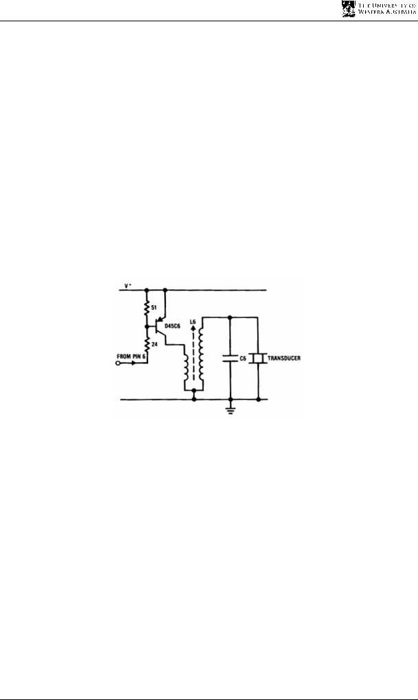
One recommendation to increase the amount of power that is outputted from the transducer is to increase the voltage across the transformer of the circuit. Figure 8.1 depicts a pulse amplifier [14]. This pulse amplifier attempts to increase the signal strength using a transistor combined with a transformer. The transistor allows for most of the supply voltage, V+, to drop across the primary of the transformer when it is switched on. V+ can be increased to allow a much higher voltage to fall across the primary windings of the transformer. Since the transformer is a step-up transformer, the voltage across the secondary winding is increased by the turns ratio of the transformer. This will allow for a greater amplitude signal that will be able to travel further.
Figure 8.1: The pulse amplifier [14]
However, care must be taken to design a pulse amplifier that only increases the range of the sensor to between 5 metres and 10 metres. This is just to enable the signal to attenuate fast enough to allow consecutive readings to occur rapidly. The current system has a range of less than 5 metres and has a sounding period of less than 6.67ms. Thus, the current time out for the echo sounder waiting for a sonar return is 10ms which can easily be accomplished by the ROBIOS function, OSWait(1). This allows approximately 100 measurements to occur each second for virtually continuous measurements.
8.1.2 The Time Variable Attenuator
A second design change involves the use of a time variable attenuator to improve the performance of the current system.
78
Chapter 8 Future Work
With the use of a single transducer, as in the current system, the echo sounder is more susceptible to ringing from the transducer. While the transducer is ringing, the system cannot detect any echoes, limiting the minimum detectable distance.
Currently, it is not possible to decrease the minimum detectable distance because the transducer’s ringing saturates the receiver. This is not a problem with the existing system because the sensors will be offset by approximately the minimum detectable distance from the extremity of the AUV.
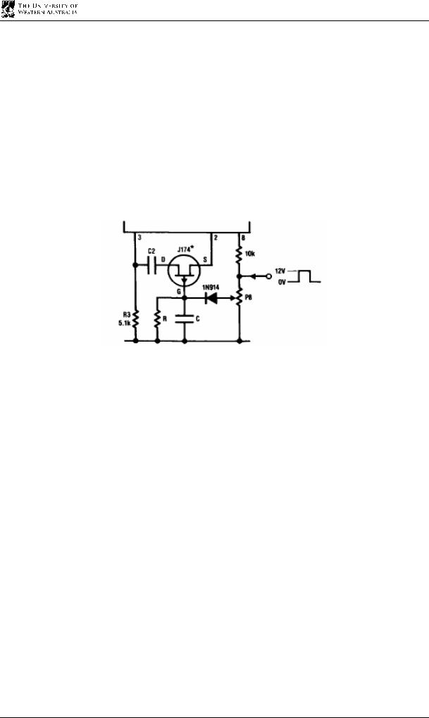
If the minimum distance is found to be too great, it can be decreased using a circuit provided by National [14]. The circuit is called a time variable attenuator.
Figure 8.2: Time variable attenuator [14]
The time variable attenuator works by changing the gain of the receiver from a minimum to a maximum over a small period of time. When the transmission pulse comes from the microcontroller, it turns the field effect transistor off, causing the gain of the receiver to become very small. This is beneficial because, at this time, the transducer’s ringing is so intense that it saturates the receiver, preventing it from detecting echoes. Since the close echoes are much stronger in intensity than the ringing, they can still be detected even when the gain is near zero. Over time, the gate voltage becomes higher and the attenuation of the receiver signal becomes much smaller. This is also beneficial as the far-range echoes become significantly less intense and require a much larger amplification than the close range echoes. These far-range echoes take longer to return and are thus amplified greater with the time variable attenuator. Thus by implementing a time variable attenuator, the detectable range is increased to include much smaller and larger values.
79

Design of an Active Acoustic Sensor System
8.2 Future Research
Some key areas are identified for possible future research in the AUV field. These areas include the development of a passive sonar system, the testing of control systems using simulations of the AUV, and researching the sonar system to provide a more realistic model of the system for use in simulations and calculations.
8.2.1 Designing a Passive Sonar Array
There are times when a passive sonar system is required. For example, in competition, the passive sonar has been used to locate a recovery zone marked by an acoustic beacon. In general underwater applications, an acoustic beacon can be used on a lost submerged vessel that the AUV may be required to find. Methods of developing a passive sonar array need to be investigated for such situations.
One simple method of designing a passive sonar unit is to use the receiver of an active sonar unit attached to an omni-directional hydrophone, which is basically an underwater microphone, instead of a directional transducer. The feasibility of using a device similar to the current unit for passive sonar detection can be investigated in future. If the device is feasible, research can be undertaken into passive sonar detection, such as in Appendix C.
8.2.2 Testing the Control System
The EKF is an extremely powerful tool in the navigation of the AUV using sensors. As is stated in Chapter 7, the EKF fuses redundant sensor readings to determine a better localisation of the AUV in its environment.
The EKF equations presented in this thesis can be used as the basis for testing the effectiveness of the EKF in navigating an AUV around the edge of a pool environment or an unstructured underwater environment.
These tests can be performed in software before implementing them in hardware. With the onset of a simulation for the AUV available for use within the university, it would be possible to test complex algorithms on realistic models of the AUV and its complement of sensors to see if it is possible to use a particular type of control system for the AUV, before committing any finance towards a hardware system. Models can be created to simulate any hardware that
80

Chapter 8 Future Work
is available on the market, so that comparisons can be made to determine the optimum type of hardware system.
8.2.3 Developing a Better Model for the Sensor System
The parameters discovered in this thesis provide some insight as to how the acoustic sensor system behaves on the AUV. A model using this information can be built into a simulation to determine the extent of its effectiveness as a sensor system on the AUV.
Further research into the modelling of the sensor system will allow a more realistic model to be achieved, meaning that the simulation software will be able to provide a more accurate representation of how the AUV will behave in a real environment.
81

Conclusion
The design of an active acoustic sensor system is presented in this thesis. There has been much work accomplished in the design phase of this project.
Much time was spent researching different approaches to solving the problem of designing a new echo sounder circuit that could fulfil the requirements set out in Chapter 3 and ensure the design’s best chance of success. After a design was chosen, it needed to be quickly converted into a physical design to initiate functional testing of the echo sounder and establish the suitability of the new circuit as a part of an active sonar system.
9.1Outcomes of the Project
There are a number of contributions that were made in this project, outlined in the sections below.
9.1.1 Designing the Echo Sounder Circuit
Many alternatives were considered in the design stage of prototyping a new echo sounder circuit. This included AM transceivers and ultrasonic switches. All these devices had a similar form of operation to an actual echo sounder. However, these designs did not meet the requirements for the project as most of these contained many components which resulted in poor SNR performance. They also used a dual transducer system, rather than a single transducer system. The chosen design was a circuit that contained a dedicated ultrasonic transceiver chip that could perform the entire signal transmission and detection. This allowed for the number of components to decrease on the circuit board and meant that a single
83

Design of an Active Acoustic Sensor System
transducer system could be implemented. The main benefit of the prototype was that it incurred a cost of less than $150 including the transducer. With the system consisting of four sensors, the total is less than $600. Thus the requirement of the system being less than $1000 was met.
9.1.2 Interfacing to the Eyebot
To allow for proper functioning of the echo sounder, some design choices needed to be made to ensure a correct interface between the Eyebot and the echo sounder.
Decisions made regarding design were:
•Making the pulse to the echo sounder come from the digital output of the Eyebot to ensure that a correctly timed pulse could be transmitted to the echo sounder. The echo sounder required a 200µs pulse.
•Making the logic output from the Eyebot would connect directly to the TPU to enable to the Eyebot to measure the time of flight of the signal, as the TPU accommodates for timing events.
Once the physical connections had been established, the focus turned to interfacing the two units. Using a flow chart for guidance, some C functions were created to properly transmit, receive, time out and read data from the echo sounder. Using a suitable time out of 10ms, the data rate was guaranteed to be approximately 100Hz, exceeding the 1Hz data rate required.
9.1.3 Hardware Verification and Experimental Results
During this stage, the echo sounder was verified as correctly interfaced to the Eyebot.
Experimentation with the echo sounder obtained some key data, such as the minimum and maximum detectable range for the current system and the speed of sound in the test medium. The error margin achieved fell within the 5cm resolution required of the sensor.
Some suggestions for improving the design of the circuit were made and a simple fault tolerant system using time redundancies was incorporated into the software to make the data from the echo sounder more robust to errors in sonar readings. Whilst not achieving the goal of a maximum detection range between 5m and 10m, the suggestions made will enable the development of a sensor that will meet this requirement.
84

Chapter 9 Conclusion
9.1.4 The Wall Following Algorithm
The EKF is used with a control system for a mobile robot designed by Bemporad et al (2000) to design a set of EKF equations and control equations for the AUV. These can be used, once the control system of the AUV is fully developed, to navigate the AUV around the edge of a pool.
9.2 Final Word
The goal of this project was to design a low active acoustic sensor system for an AUV. The design was accomplished, with effective system functioning and establishment of control equations to use with the system. Further research needs to be conducted to improve the range and modelling of the echo sounder system. However, this project has provided a platform on which future research can build on improving AUV performance in a number of different environments.
85