

Section 3: The Electromagnetic Spectrum
Your eyes are remarkable organs. They have a physiological, biological mechanism that is highly sensitive to electromagnetic radiation. Of course, the radiation that your eye detects is in the very high frequency range (short wavelength range) that we call visible light. If your eyes could actually see in the wavelengths below visible light you could look at the electromagnetic field in the air. It would have gradations of “brighter” and “dimmer” where the signal was stronger or weaker, and, in some strange sense, a different “color” for different frequencies. Perhaps 802.11 Channel 1 would be “red-like” and Channel 6 would be more “blue-like” and an area of no signal coverage would be “dimmer”.
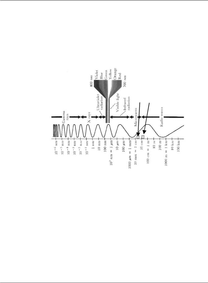
Figure 3.1 The Electromagnetic Spectrum
Unfortunately (or, perhaps, fortunately from the standpoint of human evolution) you canʼt use your eyes to see the expansion, rotation, and various disruptions and attenuations in the entire electromagnetic spectrum that surrounds you. When you see a Ferris wheel at a carnival your brain interprets the electromagnetic radiation patterns that fall on the back of your eye as a large, circular sort-of thing with seats, going around and around. When youʼre in a room with only red lights, your brain interprets the color green as if it were black because your friendʼs green shirt doesnʼt have any green light that can be reflected back to your eye. The bottom line is that when electromagnetic radiation in the visible spectrum is transmitted, reflected, absorbed, refracted, or diffracted, the resulting pattern can be observed by your eye and interpreted in some manner by your brain. You donʼt have the same luxury with the 2.4 GHz or 5.8 GHz transmissions in an 802.11 wireless
network. Consequently weʼre going to have to use our imagination to try to picture what the radiation patterns might be in a particular room, from a particular client machine, or from an access point. Perhaps the signal is being reflected off the metal Venetian blinds or filing cabinets. Perhaps the large water fountain in the courtyard is absorbing much of the transmitted energy. Perhaps that big advertising billboard outside the window is acting as a point of signal diffraction and is causing lost connectivity across the street. How can you know when you canʼt see the radiation?
Math and Physics for the 802.11 Wireless LAN Engineer |
15 |
Copyright 2003 - Joseph Bardwell