

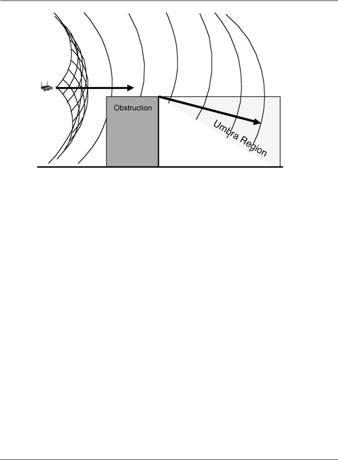
Figure 6.3 An Obstruction Causes the Wavefront to Bend
In fact, there is a sense (based on Huygensʼidea of each point on the wavefront being a new source) that the obstruction is acting like a new antenna, bending the signal as if it were the source, as indicated by the line in the figure above (6.3). The expanding wavefront to the right of the obstruction is shown with its center on the obstructionʼs edge and no longer on the original antenna.
So, the Huygens-Fresnel principle tells us that an obstacle in the 802.11 transmission path will cause the field to diffract (bend) around it, analogous to the way a water wave creates eddy currents around the piling of a pier. Diffraction can be either a good thing, or a bad thing. Itʼs good from the standpoint that it helps get RF coverage in an area; the field bends slightly around obstacles. Itʼs bad from the standpoint that the diffracted field interferes with the original field and causes potential areas of reduced coverage. The shadow zone behind the obstruction is not in line with the top of the obstruction, but takes on a cone-like shape around the obstruction as the waves bend around the object. The umbra region, also called the diffraction zone, between the shadow zone and the cone of silence is a region of weak (but not zero) signal strength. In fact, the signal strength in the cone of silence typically doesnʼt reach zero since a certain amount of reflected signal is scattered from other sources causing the cone of silence to actually manifest some signal power.
Diffraction of the Expanding Wavefront
Diffraction is the bending in the direction of travel of part of a wavefront resulting from the presence of a radio-opaque object in the transmission path. This is a characteristic of electromagnetic radiation that can not be explained solely on the basis of a particle view of signal propagation. Diffraction is a phenomenon unique to the wave-like nature of the electromagnetic field. We leave it to research in quantum mechanics to suggest reasons why diffraction is consistent with both the particle and wave view of electromagnetism and, from the perspective of 802.11 wireless networks, think of diffraction only from the wavefront perspective.
Math and Physics for the 802.11 Wireless LAN Engineer |
71 |
Copyright 2003 - Joseph Bardwell