


AMBA AHB
3.9Slave transfer responses
After a master has started a transfer, the slave then determines how the transfer should progress. No provision is made within the AHB specification for a bus master to cancel a transfer once it has commenced.
Whenever a slave is accessed it must provide a response which indicates the status of the transfer. The HREADY signal is used to extend the transfer and this works in combination with the response signals, HRESP[1:0], which provide the status of the transfer.
The slave can complete the transfer in a number of ways. It can:
•complete the transfer immediately
•insert one or more wait states to allow time to complete the transfer
•signal an error to indicate that the transfer has failed
•delay the completion of the transfer, but allow the master and slave to back off the bus, leaving it available for other transfers.
3.9.1Transfer done
The HREADY signal is used to extend the data portion of an AHB transfer. When LOW the HREADY signal indicates the transfer is to be extended and when HIGH indicates that the transfer can complete.
Note
Every slave must have a predetermined maximum number of wait states that it will insert before it backs off the bus, in order to allow the calculation of the latency of accessing the bus. It is recommended, but not mandatory, that slaves do not insert more than 16 wait states to prevent any single access locking the bus for a large number of clock cycles.
3.9.2Transfer response
A typical slave will use the HREADY signal to insert the appropriate number of wait states into the transfer and then the transfer will complete with HREADY HIGH and an OKAY response, which indicates the successful completion of the transfer.
The ERROR response is used by a slave to indicate some form of error condition with the associated transfer. Typically this is used for a protection error, such as an attempt to write to a read-only memory location.
3-20 |
© Copyright ARM Limited 1999. All rights reserved. |
ARM IHI 0011A |

AMBA AHB
The SPLIT and RETRY response combinations allow slaves to delay the completion of a transfer, but free up the bus for use by other masters. These response combinations are usually only required by slaves that have a high access latency and can make use of these response codes to ensure that other masters are not prevented from accessing the bus for long periods of time.
A full description of the SPLIT and RETRY operations can be found in Split and retry on page 3-24.
The encoding of HRESP[1:0], the transfer response signals, and a description of each response are shown in Table 3-5.
|
|
|
Table 3-5 Response encoding |
|
|
|
|
HRESP[1] |
HRESP[0] |
Response |
Description |
|
|
|
|
0 |
0 |
OKAY |
When HREADY is HIGH this shows the |
|
|
|
transfer has completed successfully. |
|
|
|
The OKAY response is also used for any |
|
|
|
additional cycles that are inserted, with |
|
|
|
HREADY LOW, prior to giving one of the |
|
|
|
three other responses. |
|
|
|
|
0 |
1 |
ERROR |
This response shows an error has occurred. |
|
|
|
The error condition should be signalled to |
|
|
|
the bus master so that it is aware the transfer |
|
|
|
has been unsuccessful. |
|
|
|
A two-cycle response is required for an error |
|
|
|
condition. |
|
|
|
|
1 |
0 |
RETRY |
The RETRY response shows the transfer has |
|
|
|
not yet completed, so the bus master should |
|
|
|
retry the transfer. The master should |
|
|
|
continue to retry the transfer until it |
|
|
|
completes. |
|
|
|
A two-cycle RETRY response is required. |
|
|
|
|
1 |
1 |
SPLIT |
The transfer has not yet completed |
|
|
|
successfully. The bus master must retry the |
|
|
|
transfer when it is next granted access to the |
bus. The slave will request access to the bus on behalf of the master when the transfer can complete.
A two-cycle SPLIT response is required.
When it is necessary for a slave to insert a number of wait states prior to deciding what response will be given then it must drive the response to OKAY.
ARM IHI 0011A |
© Copyright ARM Limited 1999. All rights reserved. |
3-21 |
AMBA AHB
3.9.3Two-cycle response
Only an OKAY response can be given in a single cycle. The ERROR, SPLIT and RETRY responses require at least two cycles. To complete with any of these responses then in the penultimate (one before last) cycle the slave drives HRESP[1:0] to indicate ERROR, RETRY or SPLIT while driving HREADY LOW to extend the transfer for an extra cycle. In the final cycle HREADY is driven HIGH to end the transfer, while HRESP[1:0] remains driven to indicate ERROR, RETRY or SPLIT.
If the slave needs more than two cycles to provide the ERROR, SPLIT or RETRY response then additional wait states may be inserted at the start of the transfer. During this time the HREADY signal will be LOW and the response must be set to OKAY.
The two-cycle response is required because of the pipelined nature of the bus. By the time a slave starts to issue either an ERROR, SPLIT or RETRY response then the address for the following transfer has already been broadcast onto the bus. The twocycle response allows sufficient time for the master to cancel this address and drive HTRANS[1:0] to IDLE before the start of the next transfer.
For the SPLIT and RETRY response the following transfer must be cancelled because it must not take place before the current transfer has completed. However, for the ERROR response, where the current transfer is not repeated, completion of the following transfer is optional.
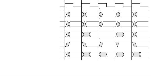
Figure 3-13 shows an example of a RETRY operation.
HCLK
HTRANS[1:0]
HADDR[31:0]
HWDATA[31:0]
HREADY
HRESP[1:0]
T1 |
T2 |
T3 |
|
NONSEQ |
SEQ |
|
A |
A + 4 |
|
|
Data |
|
|
(A) |
|
|
RETRY |
T4 |
T5 |
IDLE |
NONSEQ |
|
A |
RETRY |
OKAY |
Figure 3-13 Transfer with retry response
3-22 |
© Copyright ARM Limited 1999. All rights reserved. |
ARM IHI 0011A |
AMBA AHB
The following events are illustrated:
•The master starts with a transfer to address A.
•Before the response is received for this transfer the master moves the address on to A + 4.
•The slave at address A is unable to complete the transfer immediately and therefore it issues a RETRY response. This response indicates to the master that the transfer at address A is unable to complete and so the transfer at address A + 4 is cancelled and replaced by an IDLE transfer.
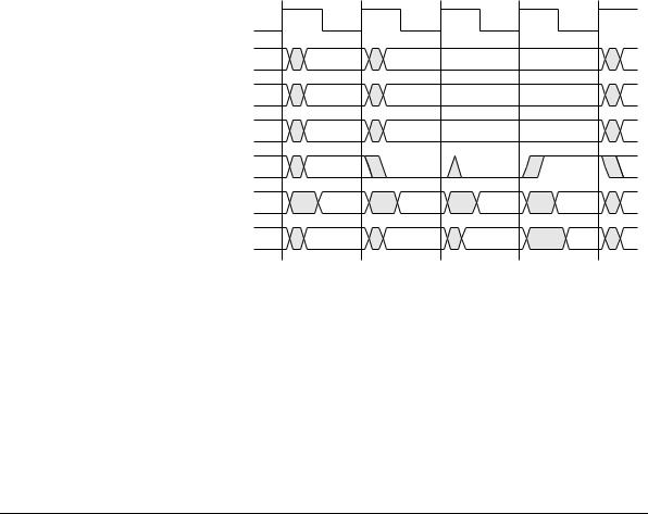
Figure 3-14 shows a transfer where the slave requires one cycle to decide on the response it is going to give (during which time HRESP indicates OKAY) and then the slave ends the transfer with a two-cycle ERROR response.
HCLK
HADDR[31:0]
Control
HWDATA[31:0]
HREADY
HRESP[31:0]
HRDATA[31:0]
A
Control
OKAY
Data |
(A) |
ERROR |
ERROR |
Figure 3-14 Error response
3.9.4Error response
If a slave provides an ERROR response then the master may choose to cancel the remaining transfers in the burst. However, this is not a strict requirement and it is also acceptable for the master to continue the remaining transfers in the burst.
ARM IHI 0011A |
© Copyright ARM Limited 1999. All rights reserved. |
3-23 |