

Digital Design VHDL Laboratory
3.State Machines and Programmable Logic Devices
Pepe, 4/5/96. 5/23/96
state_clocking: process(clk) begin if (clk'event and clk='1') then
present_state <= next_state; end if;
end process state_clocking;
moore_output: process(present_state) begin if (present_state=HIGH1) then
output <= '1'; else
output <= '0'; end if;
end process moore_output;
end moore_machine;
Listing 3-2. Moore Machine VHDL Code
3.4 Problems
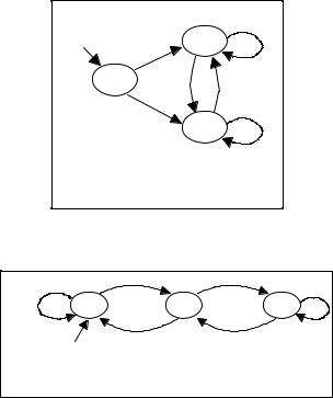
1)Convert the Moore machine in Figure 3-7 into a Mealy machine. Implement the Mealy machine in VHDL and simulate it with Cypress NOVA simulator.
|
|
0/1 |
Start |
0/0 |
q1 |
|
|
|
q0 |
1/0 |
0/0 |
|
||
|
1/0 |
1/1 |
|
|
|
|
|
q2 |
Figure 3-7. Question #1
2)Simulate the state machine shown in Figure 3-8 with VHDL and describe what it does (Hint: See next question).
1 |
|
0 |
0 |
|
1 |
|
|
|
q0/0 |
q1/1 |
q2/2 |
1 |
|
0 |
Start |
|
|
Figure 3-8. Question #2
3)Design a Mealy state machine that computes the remainder of value 5 instead 3. Draw the state diagram and simulate it with VHDL. Test the machine using input 3, 4, 5, 6, 76, and 101.
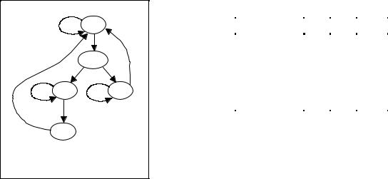
4)Design the state machine of the state flow diagram in Figure 3-9 and the output table in Table 3-3.
24 |
Copyright 1996, CERL / EE, V1.00 |
frame
|
IDLE |
|
|
/frame |
|
|
|
f |
|
|
r |
|
DECODE |
am |
|
e |
|
hit |
|
/hit |
|
|
|
/frame |
/frame |
|
XFER |
|
BUSY |
XFER2
Figure 3-9. State Flow Diagram
Digital Design VHDL Laboratory 3.State Machines and Programmable Logic Devices Pepe, 4/5/96. 5/23/96
Table 3-3. |
|
|
|
||||
|
|
|
|
|
|
|
|
State / Output |
|
OE |
|
|
GO |
|
ACT |
IDLE |
0 |
|
|
0 |
0 |
||
DECODE |
|
|
|
0 |
0 |
||
0 |
|
|
|||||
BUSY |
|
|
|
0 |
1 |
||
0 |
|
|
|||||
XFER |
|
|
|
1 |
1 |
||
1 |
|
|
|||||
XFER2 |
|
|
|
0 |
1 |
||
1 |
|
|
|||||
25 |
Copyright 1996, CERL / EE, V1.00 |